Advanced Power Technology reserves the right to change, without notice, the specifications and information contained
herein. Visit our web site at
www.advancedpower.com
or contact our factory direct.
GENERAL DESCRIPTION
The UMIL10 is a COMMON EMITTER broadband transistor specifically
intended for use in the 100-400 MHz frequency band. It may be operated in
Class AB or C. Gold metallization and silicon diffused resistors ensure
ruggedness and high reliability.
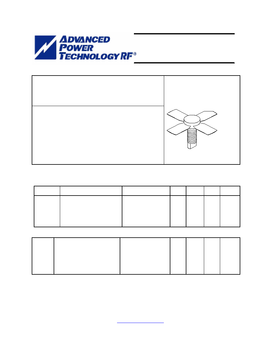
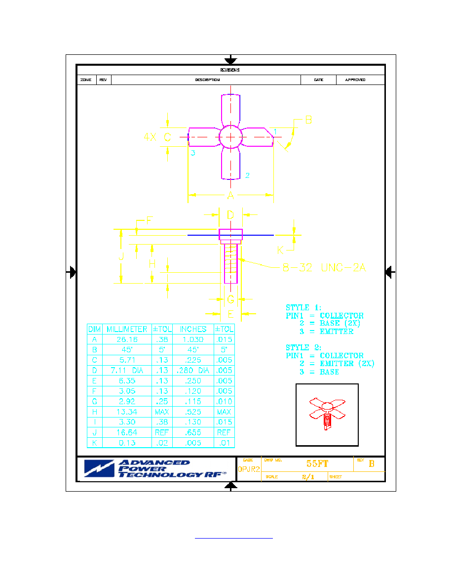
CASE OUTLINE
55FT, Style 2
ABSOLUTE MAXIMUM RATINGS
Maximum Power Dissipation @ 25
o
C 28 Watts
Maximum Voltage and Current
BVces Collector to Emiter Voltage 55 Volts
BVebo Emitter to Base Voltage 4.0 Volts
Ic Collector Current 1.5 A
Maximum Temperatures
Storage Temperature - 65 to +150
o
C
Operating Junction Temperature +200
o
C
ELECTRICAL CHARACTERISTICS @ 25
O
C
SYMBOL
CHARACTERISTICS
TEST CONDITIONS
MIN
TYP
MAX
UNITS
Pout
Pin
Pg
c
VSWR
Power Output
Power Input
Power Gain
Efficiency
Load Mismatch Tolerance
F = 400 MHz
Vcc = 28 Volts
Class C Bias
10
10.0
60
1.0
30:1
Watts
Watts
dB
%
BVebo
BVces
BVceo
Cob
h
FE
jc
Emitter to Base Breakdown
Collector to Emitter Breakdown
Collector to Emitter Breakdown
Output Capacitance
DC - Current Gain
Thermal Resistance
Ie = 5 mA
Ic = 50 mA
Ie = 50 mA
Vcb = 28 V, F = 1 MHz
Vce = 5 V, Ic = 200 mA
4.0
55
30
10
11.5
6.3
Volts
Volts
Volts
pF
o
C/W
Rev. A : August 2005
UMIL 10
100 Watts, 28 Volts, Class AB or C
Defcom 100 - 400
MHz
Advanced Power Technology reserves the right to change, without notice, the specifications and information contained
herein. Visit our web site at
www.advancedpower.com
or contact our factory direct.