Agilent HLMP-ABxx, HLMP-BBxx, HLMP-
ADxx, HLMP-BDxx, HLMP-AGxx, HLMP-
BGxx, HLMP-ALxx, HLMP-BLxx,
HLMP-AMxx, HLMP-BMxx T-1
3
/
4
(5 mm)
Oval Precision Optical Performance
AlInGaP and InGaN Lamps
Data Sheet
Features
· Well defined spatial radiation
pattern
· Viewing angles:
Major axis 70°
Minor axis 35°
· High luminous output
· Red and Amber Intensity are
available for:
AlInGaP (Bright)
AlInGaP II (Brightest)
· Colors:
472 nm blue
526 nm green
626 nm red
630 nm red
590 nm amber
592 nm amber
· Superior resistance to moisture
· UV resistant epoxy
Benefits
· Viewing angle designed for wide
field of view application
· Red, green, and blue radiation
patterns matched for full color
sign
· Superior performance in outdoor
environments
Applications
· Full color/video signs
Description
These Precision Optical
Performance Oval LEDs are
specifically designed for full
color/video and passenger
information signs. The oval
shaped radiation pattern
(35
° x 70°) and high luminous
intensity ensure that these
devices are excellent for wide
field of view outdoor application
where a wide viewing angle and
readability in sunlight are
essential. These lamps have very
smooth, matched radiation
patterns ensuring consistent
color mixing in full color
applications, message uniformity
across the viewing angle of the
sign.
High efficiency LED material is
used in these lamps: Aluminum
Indium Gallium Phosphide
(AlInGaP) for amber and red,
and Indium Gallium Nitride
(InGaN) for blue and green. Each
lamp is made with an advance
optical grade epoxy offering
superior high temperature and
high moisture resistance in
outdoor applications. The
package epoxy contains both
UV-A and UV-B inhibitors to
reduce the effects of long term
exposure to direct sunlight.
Designers can select parallel or
perpendicular orientation. Both
lamps are available in tinted
version.
CAUTION: The blue and green LEDs are Class 1 ESD sensitive. Please observe appropriate
precautions during handling and processing. Refer to Agilent Application Note AN-1142 for
additional details.
3
Table 2. LED Indicators
Device Selection Guide for AlInGaP
Color and
Luminous
Luminous
Dominant
Intensity,
Intensity,
Leads
Wavelength
I
v
(mcd) at
I
v
(mcd) at
with
Leadframe
Package
Part Number
d
(nm) Typ.
20 mA Min.
20 mA Max.
Stand-offs
Orientation
Drawing
HLMP-AG01-K00xx
Red 626
310
No
Parallel
A
HLMP-AG11-KN0xx
Red 626
310
880
Yes
Parallel
B
HLMP-AL01-K00xx
Amber 590
310
No
Parallel
A
HLMP-AL01-LP0xx
Amber 590
400
1150
No
Parallel
A
HLMP-AL01-NR0xx
Amber 590
680
1900
No
Parallel
A
HLMP-AL11-KN0xx
Amber 590
310
880
Yes
Parallel
B
HLMP-AL11-NR0xx
Amber 590
680
1900
Yes
Parallel
B
HLMP-BG01-LM0xx
Red 626
400
520
No
Perpendicular
C
HLMP-BG01-MN0xx
Red 626
520
880
No
Perpendicular
C
HLMP-BG11-KN0xx
Red 626
310
880
Yes
Perpendicular
D
HLMP-BL01-NR0xx
Amber 590
680
1900
No
Perpendicular
C
HLMP-BL11-KN0xx
Amber 590
310
880
Yes
Perpendicular
D
HLMP-BL11-NR0xx
Amber 590
680
1900
Yes
Perpendicular
D
Table 3. Device Selection Guide for InGaN
Color and Dominant Luminous Intensity,
Leads with
Leadframe
Package
Part Number
Wavelength d (nm) Typ. Iv (mcd) at 20 mA Min.
Stand-offs
Orientation
Drawing
HLMP-AB01-J00xx
Blue 472
240
No
Parallel
A
HLMP-BB11-J00xx
Blue 472
240
Yes
Perpendicular
D
HLMP-BB11-K00xx
Blue 472
310
Yes
Perpendicular
D
HLMP-BM11-L00xx
Green 526
400
Yes
Perpendicular
D
HLMP-BM11-Q00xx
Green 526
1150
Yes
Perpendicular
D
HLMP-AB11-J00xx
Blue 472
240
Yes
Parallel
B
HLMP-AM01-Q00xx
Green 526
1150
No
Parallel
A
HLMP-BB01-J0Bxx
Blue 472
240
No
Perpendicular
C
HLMP-BB11-KN0xx
Blue 472
310
Yes
Perpendicular
D
HLMP-BM01-L00xx
Green 526
400
No
Perpendicular
C
Tolerance for intensity range limit is ±15%.
4
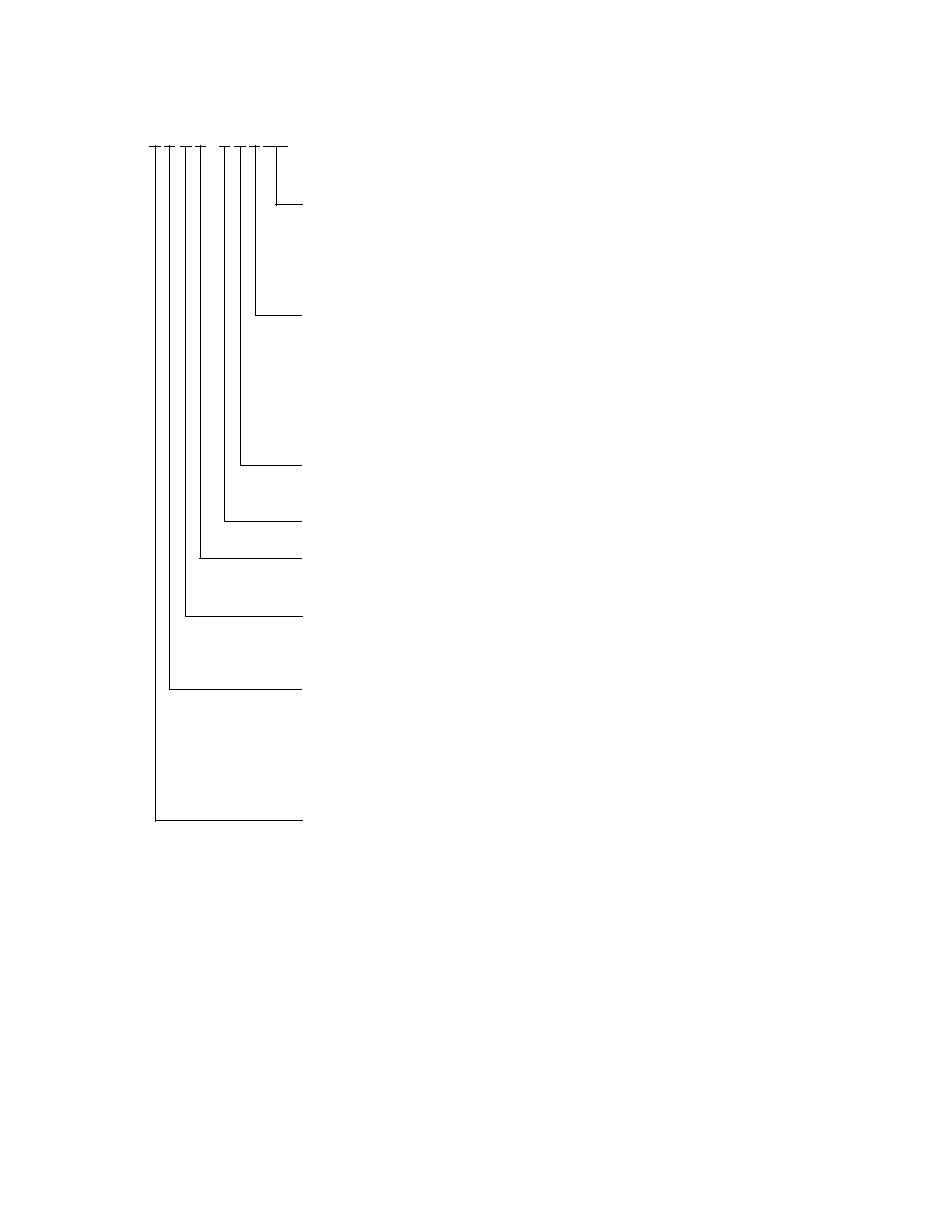
Part Numbering System
HLMP-X X X X - X X X XX
Mechanical Options
00: Bulk Packaging
DD: Ammo Pack
YY: Flexi-Bin; Bulk Packaging
ZZ: Flexi-Bin; Ammo Pack
Color Bin
0: No Color Bin Limitation
R: Color Bins 1, 2, 4, and 6 with V
F
max of 2.6 V
T: Red Color with V
F
max of 2.6 V
B: Color bin 2 and 3 only
K: Color bins 2 and 4 only
S: Color bins 2 and 4 with VF max of 2.6 V
Maximum Intensity Bin
0: No Iv Bin Limitation
Minimum Intensity Bin
Tint Option
1 or 6: Matching Color Tints
Standoff Option
0: Without
1: With
Color
B: 472 nm Blue
D: 630 nm Red
G: 626 nm Red
L: 590 or 592 nm Amber
M: 526 nm Green
Package
A: 5 mm 35
° x 70° Oval, Parallel
B: 5 mm 35
° x 70° Oval, Perpendicular
5
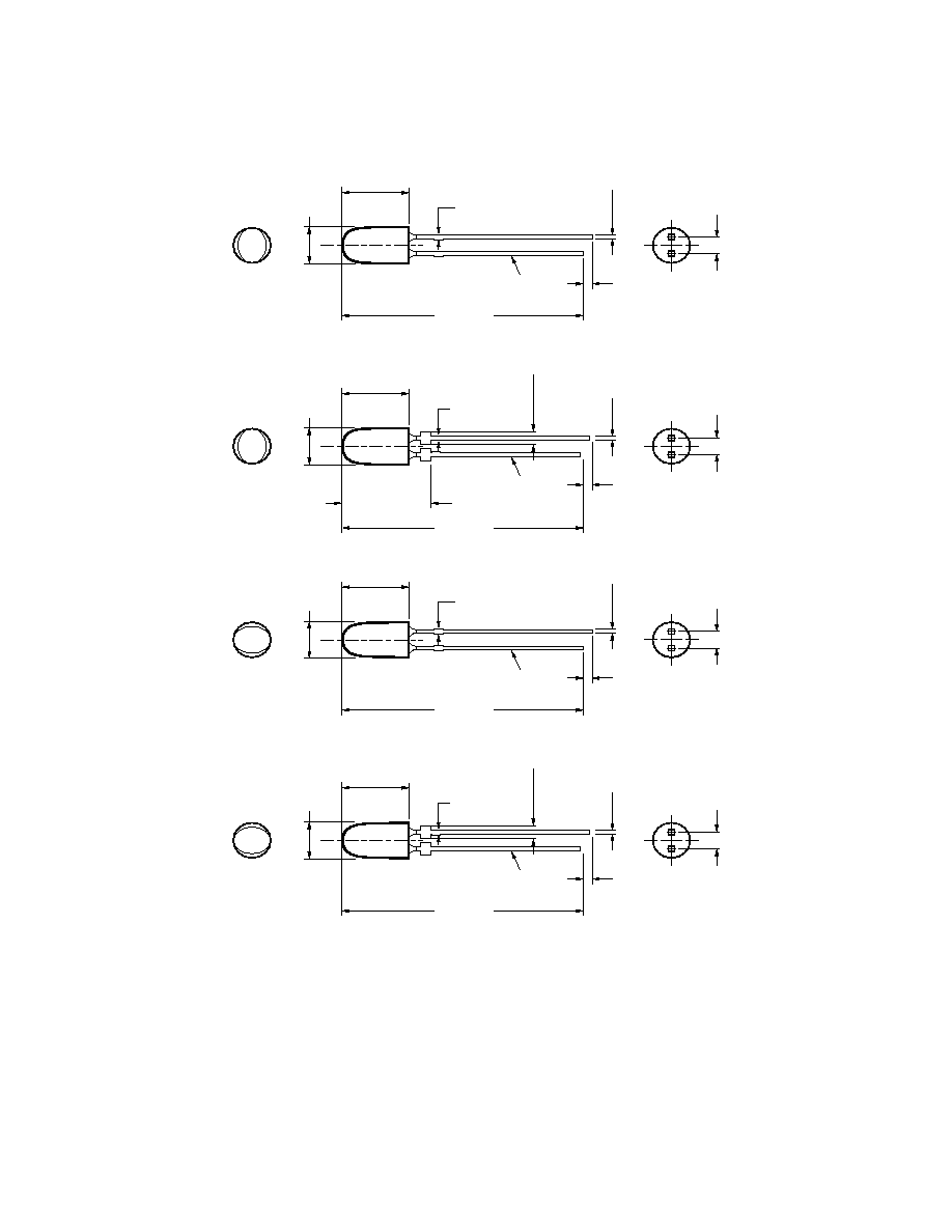
Package Dimensions
5.00
±
0.20
(0.197
±
0.008)
31.60
(1.244)
MIN.
0.70 (0.028)
MAX.
1.00
(0.039)
MIN.
8.71
±
0.20
(0.343
±
0.008)
2.54
±
0.38
(0.100
±
0.015)
0.50
±
0.10
(0.020
±
0.004)
SQ. TYP.
CATHODE
LEAD
5.00
±
0.20
(0.197
±
0.008)
31.60
(1.244)
MIN.
0.70 (0.028)
MAX.
1.00
(0.039)
MIN.
8.71
±
0.20
(0.343
±
0.008)
2.54
±
0.38
(0.100
±
0.015)
0.50
±
0.10
(0.020
±
0.004)
SQ. TYP.
CATHODE
LEAD
1.50
±
0.15
(0.059
±
0.006)
5.00
±
0.20
(0.197
±
0.008)
31.60
(1.244)
MIN.
0.70 (0.028)
MAX.
1.00
(0.039)
MIN.
8.71
±
0.20
(0.343
±
0.008)
2.54
±
0.38
(0.100
±
0.015)
0.50
±
0.10
(0.020
±
0.004)
SQ. TYP.
CATHODE
LEAD
5.00
±
0.20
(0.197
±
0.008)
31.60
(1.244)
MIN.
0.70 (0.028)
MAX.
1.00
(0.039)
MIN.
8.71
±
0.20
(0.343
±
0.008)
2.54
±
0.38
(0.100
±
0.015)
0.50
±
0.10
(0.020
±
0.004)
SQ. TYP.
CATHODE
LEAD
1.50
±
0.15
(0.059
±
0.006)
A
B
C
D
11.70
+ 0.13
0.08
0.461
+ 0.005
0.003
)
(
NOTES:
1. ALL DIMENSIONS ARE IN MILLIMETERS (INCHES).
2. LEADS ARE MILD STEEL, SOLDER DIPPED.
3. TAPERS SHOWN AT TOP OF LEADS (BOTTOM OF LAMP PACKAGE) INDICATE AN
EPOXY MENISCUS THAT MAY EXTEND ABOUT 1 mm (0.040 IN.) DOWN THE LEADS.
4. RECOMMENDED PC BOARD HOLE DIAMETERS:
LAMP PACKAGES A AND C WITHOUT STAND-OFFS: FLUSH MOUNTING AT BASE
OF LAMP PACKAGE = 1.143/1.067 mm (0.044/0.042 IN.).
LAMP PACKAGES B AND D WITH STAND-OFFS: MOUNTING AT LEAD STAND-OFFS.