T-1
3/4
(5 mm) Oval Precision
Optical Performance LED Lamps
Technical Data
Sun Power Series
HLMP-ABxx
HLMP-BBxx
HLMP-ADxx
HLMD-BDxx
HLMP-AGxx
HLMP-BGxx
HLMP-ALxx
HLMP-BLxx
HLMP-AMxx HLMP-BMxx
CAUTION: The Blue and Green LEDs are Class 1 ESD sensitive. Please observe appropriate
precautions during handling and processing. Refer to Agilent Application Note AN-1142 for
additional details.
Features
∑ Smooth, Consistent Spatial
Radiation Patterns
∑ Wide Viewing Angle
Major Axis 70∞
Minor Axis 35∞
∑ High Luminous Output
∑ Two Red and Amber
Intensity Levels Available:
AlInGaP (bright) and
AlInGaP II (brightest)
∑ Colors:
472 nm Blue
526 nm Green
590/592 nm Amber
626/630 nm Red
∑ Superior Resistance to
Moisture
∑ UV Resistant Epoxy
∑ Choice of Package Options
Applications
∑ Full Color/Video Signs
∑ Variable Message Signs
Passenger Information
Advertising
Time/Temperature
Benefits
∑ Viewing Angle Designed for
Wide Field of View
Applications
∑ Red, Green, and Blue
Radiation Patterns Matched
for Full Color Signs
∑ Superior Outdoor
Environmental Performance
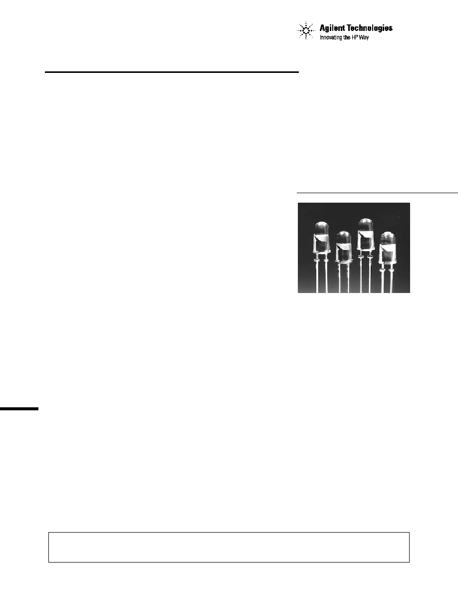
Description
These Precision Optical
Performance oval LEDs are
specifically designed for Full
Color/Video and Passenger
Information signs. The oval
shaped radiation pattern (35∞ x
70∞) and high luminous intensity
ensure that these devices are
excellent for wide field of view
outdoor applications where a wide
viewing angle and readability in
sunlight are essential. These
lamps have very smooth, matched
radiation patterns ensuring
consistent color mixing in full
color applications, and message
uniformity across the viewing
angle of the sign.
High efficiency LED materials are
used in these lamps: Aluminum
Indium Gallium Phosphide
(AlInGaP) for amber and red, and
Indium Gallium Nitride (InGaN)
for blue and green. There are two
families of red and amber lamps,
AlInGaP and the higher
performance AlInGaP II. Each
lamp is made with an advanced
optical grade epoxy offering
superior high temperature and
high moisture resistance in
outdoor applications. The
package epoxy contains both
UV-a and UV-b inhibitors to
reduce the effects of long term
exposure to direct sunlight.
Designers can select parallel
(where the axis of the leads is
parallel to the wide axis of the
oval radiation pattern) or
perpendicular orientation.
Designers can also choose
between lamps with or without
standoffs. The red and amber
lamps are available in tinted
versions.
2
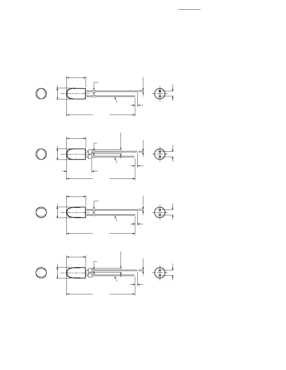
Package Dimensions
NOTES:
1. ALL DIMENSIONS ARE IN MILLIMETERS (INCHES).
2. LEADS ARE MILD STEEL, SOLDER DIPPED.
3. TAPERS SHOWN AT TOP OF LEADS (BOTTOM OF LAMP PACKAGE) INDICATE AN
EPOXY MENISCUS THAT MAY EXTEND ABOUT 1 mm (0.040 IN.) DOWN THE LEADS.
4. RECOMMENDED PC BOARD HOLE DIAMETERS:
≠ LAMP PACKAGES A AND C WITHOUT STAND-OFFS: FLUSH MOUNTING AT BASE
OF LAMP PACKAGE = 1.143/1.067 mm (0.044/0.042 IN.).
≠ LAMP PACKAGES B AND D WITH STAND-OFFS: MOUNTING AT LEAD STAND-OFFS.
5.00 ± 0.20
(0.197 ± 0.008)
31.60
(1.244)
MIN.
0.70 (0.028)
MAX.
1.00
(0.039)
MIN.
8.71 ± 0.20
(0.343 ± 0.008)
2.54 ± 0.38
(0.100 ± 0.015)
0.50 ± 0.10
(0.020 ± 0.004)
SQ. TYP.
CATHODE
LEAD
5.00 ± 0.20
(0.197 ± 0.008)
31.60
(1.244)
MIN.
0.70 (0.028)
MAX.
1.00
(0.039)
MIN.
8.71 ± 0.20
(0.343 ± 0.008)
2.54 ± 0.38
(0.100 ± 0.015)
0.50 ± 0.10
(0.020 ± 0.004)
SQ. TYP.
CATHODE
LEAD
1.50 ±0.15
(0.059 ± 0.006)
5.00 ± 0.20
(0.197 ± 0.008)
31.60
(1.244)
MIN.
0.70 (0.028)
MAX.
1.00
(0.039)
MIN.
8.71 ± 0.20
(0.343 ± 0.008)
2.54 ± 0.38
(0.100 ± 0.015)
0.50 ± 0.10
(0.020 ± 0.004)
SQ. TYP.
CATHODE
LEAD
5.00 ± 0.20
(0.197 ± 0.008)
31.60
(1.244)
MIN.
0.70 (0.028)
MAX.
1.00
(0.039)
MIN.
8.71 ± 0.20
(0.343 ± 0.008)
2.54 ± 0.38
(0.100 ± 0.015)
0.50 ± 0.10
(0.020 ± 0.004)
SQ. TYP.
CATHODE
LEAD
1.50 ±0.15
(0.059 ± 0.006)
A
B
C
D
11.70
+ 0.13
≠ 0.08
0.461
+ 0.005
≠ 0.003
)
(
3
Part Numbering Scheme
HLMP-(1)(2)(3)(4)
where (1) = Leadframe
Orientation
"A" = Parallel
"B" = Perpendicular
where (2) = Color Option
"L" = 590/592 nm Amber
"G" = 626 nm Red
"D" = 630 nm Red
"M" = 525 nm Green
"B" = 472 nm Blue
where (3) = Standoff Option
"0" = Without
"1" = With
where (4) = Tint Option
"1" or "6" =
Matching Color
Tints
Refer to selection guides for
available combinations.
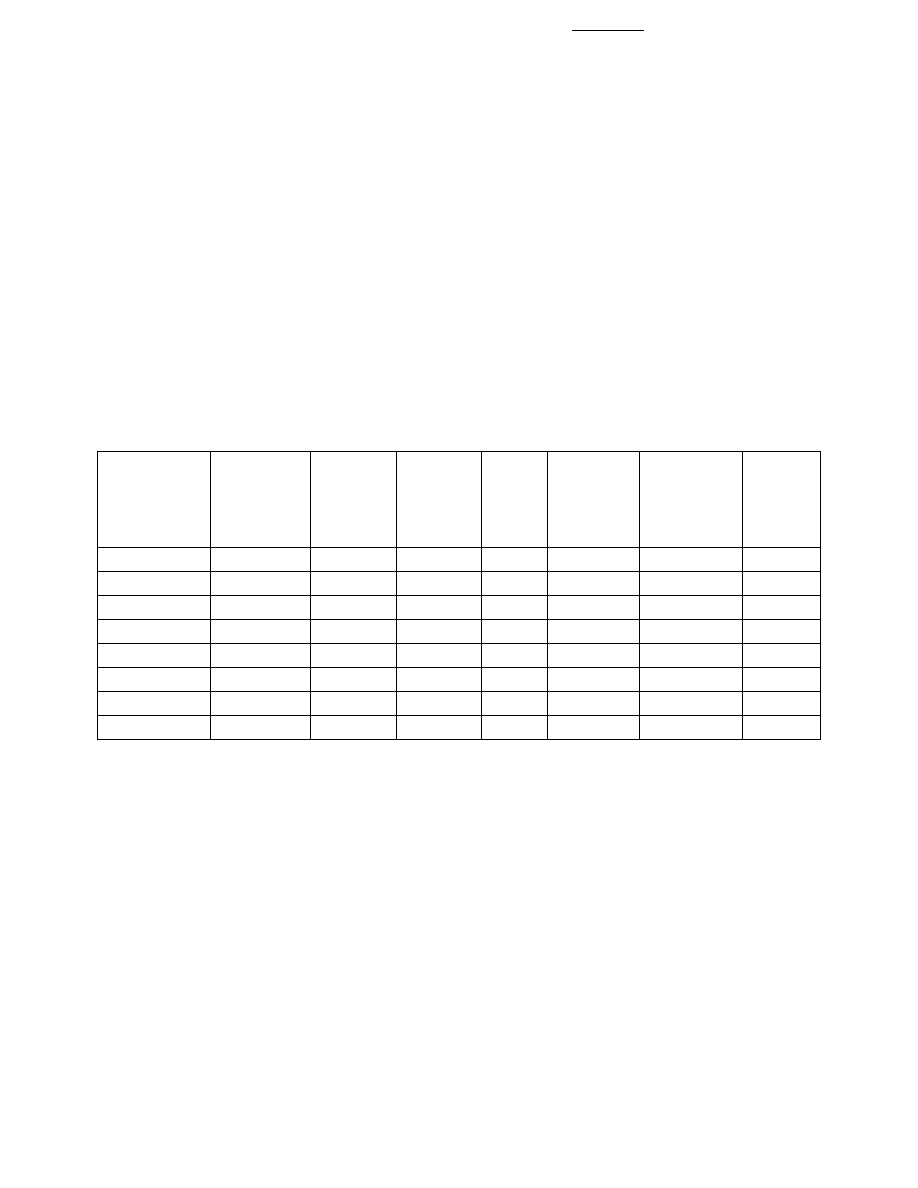
AlInGaP Device Selection Guide (Amber, Red)
Color and
Luminous
Luminous
Typical
Intensity
Intensity
Dominant
I
V
(mcd) at I
V
(mcd) at
Leads
Lead
Wavelength
20 mA
20 mA
Tinting
with
Frame
Package
Part Number
d
(nm)
Min.
Typ.
Type
Stand-Offs
Orientation
Drawing
HLMP-AL01
Amber 590
270
600
Amber
No
Parallel
A
HLMP-AL11
Amber 590
270
600
Amber
Yes
Parallel
B
HLMP-BL01
Amber 590
270
600
Amber
No
Perpendicular
C
HLMP-BL11
Amber 590
270
600
Amber
Yes
Perpendicular
D
HLMP-AG01
Red 626
270
600
Red
No
Parallel
A
HLMP-AG11
Red 626
270
600
Red
Yes
Parallel
B
HLMP-BG01
Red 626
270
600
Red
No
Perpendicular
C
HLMP-BG11
Red 626
270
600
Red
Yes
Perpendicular
D
Notes:
1. The luminous intensity is measured on the mechanical axis of the lamp package.
2. The optical axis is closely aligned with the package mechanical axis.
3. The dominant wavelength
d
, is derived from the CIE Chromaticity Diagram and represents the color of the lamp.
4
InGaN Device Selection Guide (Blue, Green)
Color and
Luminous
Luminous
Typical
Intensity
Intensity
Dominant
I
V
(mcd) at I
V
(mcd) at
Leads
Lead
Wavelength
20 mA
20 mA
Tinting
with
Frame
Package
Part Number
d
(nm)
Min.
Typ.
Type
Stand-Offs
Orientation
Drawing
HLMP-AM01
Green 526
590
1300
Green
No
Parallel
A
HLMP-AM11
Green 526
590
1300
Green
Yes
Parallel
B
HLMP-BM01
Green 526
590
1300
Green
No
Perpendicular
C
HLMP-BM11
Green 526
590
1300
Green
Yes
Perpendicular
D
HLMP-AB01
Blue 472
205
400
Blue
No
Parallel
A
HLMP-AB11
Blue 472
205
400
Blue
Yes
Parallel
B
HLMP-BB01
Blue 472
205
400
Blue
No
Perpendicular
C
HLMP-BB11
Blue 472
205
400
Blue
Yes
Perpendicular
D
Notes:
1. The luminous intensity is measured on the mechanical axis of the lamp package.
2. The optical axis is closely aligned with the package mechanical axis.
3. The dominant wavelength
d
, is derived from the CIE Chromaticity Diagram and represents the color of the lamp.
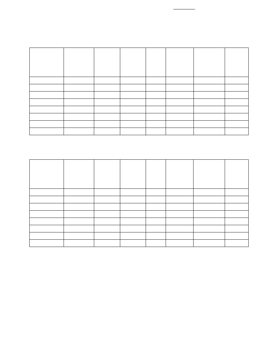
AlInGaP2 Device Selection Guide (Amber, Red)
Color and
Luminous
Luminous
Typical
Intensity
Intensity
Dominant
I
V
(mcd) at I
V
(mcd) at
Leads
Lead
Wavelength
20 mA
20 mA
Tinting
with
Frame
Package
Part Number
d
(nm)
Min.
Typ.
Type
Stand-Offs
Orientation
Drawing
HLMP-AL06
Amber 592
590
1300
Amber
No
Parallel
A
HLMP-AL16
Amber 592
590
1300
Amber
Yes
Parallel
B
HLMP-BL06
Amber 592
590
1300
Amber
No
Perpendicular
C
HLMP-BL16
Amber 592
590
1300
Amber
Yes
Perpendicular
D
HLMP-AD06
Red 630
590
1300
Red
No
Parallel
A
HLMP-AD16
Red 630
590
1300
Red
Yes
Parallel
B
HLMP-BD06
Red 630
590
1300
Red
No
Perpendicular
C
HLMP-BD16
Red 630
590
1300
Red
Yes
Perpendicular
D
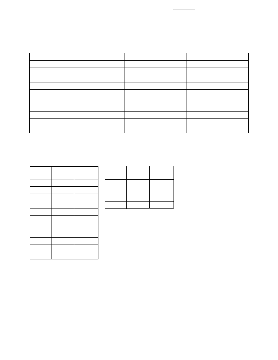
5
Absolute Maximum Ratings at 25∞C
Amber and Red
Blue and Green
DC Forward Current
50 mA
30 mA
Peak Pulsed Forward Current
70 mA
100 mA
Average Forward Current (Pulsed Operation)
30 mA
[1]
30 mA
Reverse Voltage (I
R
= 100
µ
A)
5 V
Reverse Voltage (I
R
= 10
µ
A)
5 V
Power Dissipation
120 mW
120 mW
LED Junction Temperature
130∞C
100∞C
Operating Temperature Range
≠40∞C to +100∞C
≠40∞C to +80∞C
Storage Temperature Range
≠40∞C to +120∞C
≠40∞C to +100∞C
Soldering Temperature
260∞C for 5 sec.
260∞C for 5 sec.
Bin
Name
Min.
Max.
G
140
180
H
180
240
J
240
310
K
310
400
L
400
520
M
520
680
N
680
880
P
880
1150
Q
1150
1500
R
1500
1900
S
1900
2500
Intensity Bin Limits
(mcd at 20 mA)
Tolerance for each bin limit is
±
15%.
Bin
Name
Min.
Max.
1
584.5
587.0
2
587.0
589.5
4
589.5
592.0
6
592.0
594.5
HLMP-xLxx Color Bin
Limits (nm at 20 mA)
Tolerance for each bin limit is
±
0.5 nm.
Note:
1. Bin categories are established for classification of products. Products may not be
available in all bin categories. Please contact your Agilent representative for
information on currently available bins.
Note:
1. Higher pulsed average currents can be used under certain conditions. Refer to Agilent Application Brief I-024.