 | –≠–ª–µ–∫—Ç—Ä–æ–Ω–Ω—ã–π –∫–æ–º–ø–æ–Ω–µ–Ω—Ç: HLMP-C215 | –°–∫–∞—á–∞—Ç—å:  PDF PDF  ZIP ZIP |
T-1
3
/
4
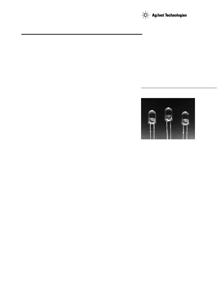
Super Ultra-Bright LED
Lamps
Technical Data
HLMP-C115
HLMP-C117
HLMP-C123
HLMP-C215
HLMP-C223
HLMP-C315
HLMP-C323
HLMP-C415
HLMP-C423
HLMP-C515
HLMP-C523
HLMP-C615
HLMP-C623
Features
∑ Very High Intensity
∑ Exceptional Uniformity
∑ Microtint Lens for Color
Identification
∑ Consistent Viewability
All Colors:
AlGaAs Red
High Efficiency Red
Yellow
Orange
Green
Emerald Green
∑ 15
∞
and 25
∞
Family
∑ Tape and Reel Options
Available
∑ Binned for Color and
Intensity
Applications
∑ Ideal for Backlighting Front
Panels*
∑ Used for Lighting Switches
∑ Adapted for Indoor and
Outdoor Signs
Description
These non-diffused lamps are
designed to produce a bright light
source and smooth radiation pat-
tern. A slight tint is added to the
lens for easy color identification.
This lamp has been designed with
a 20 mil lead frame, enhanced
flange, and tight meniscus
controls, making it compatible
with radial lead automated
insertion equipment.
2
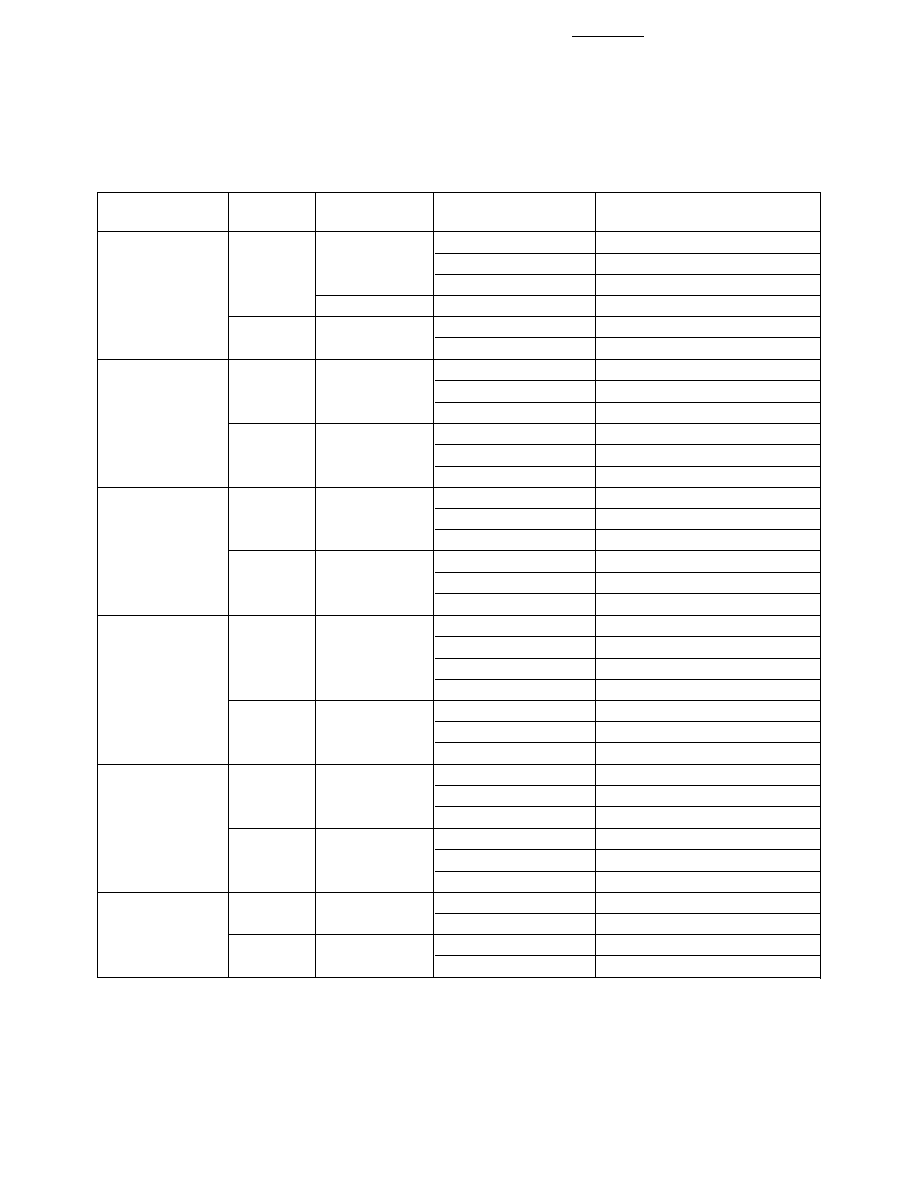
Selection Guide
Part Number Luminous Intensity Iv (mcd)
Color
2
1/2[1]
Standoff Leads
HLMP-
Min.
Max.
DH AS AlGaAs
15
No
C115
290.0
≠
C115-O00xx
290.0
≠
C115-OP0xx
290.0
1000.0
Yes
C117-OP0xx
290.0
1000.0
25
No
C123
90.2
≠
C123-L00xx
90.2
≠
Red
15
No
C215
138.0
≠
C215-M00xx
138.0
≠
C215-MN0xx
138.0
400.0
25
No
C223
90.2
≠
C223-L00xx
90.2
≠
C223-MN0xx
138.0
400.0
Yellow
15
No
C315
147.0
≠
C315-L00xx
147.0
≠
C315-LM0xx
147.0
424.0
25
No
C323
96.2
≠
C323-K00xx
96.2
≠
C323-KL0xx
96.2
294.0
Orange
15
No
C415
138.0
≠
C415-M00xx
138.0
≠
C415-M0D0xx
138.0
≠
C415-MN0xx
138.0
400.0
25
No
C423
90.2
≠
C423-L00xx
90.2
≠
C423-LM0xx
90.2
276.0
Green
15
No
C515
170.0
≠
C515-L00xx
170.0
C515-LM0xx
170.0
490.0
25
No
C523
69.8
≠
C523-J00xx
69.8
≠
C523-KL0xx
111.7
340.0
Emerald Green
15
No
C615
17.0
≠
C615-G00xx
17.0
≠
25
No
C623
6.7
≠
C623-E00xx
6.7
≠
3
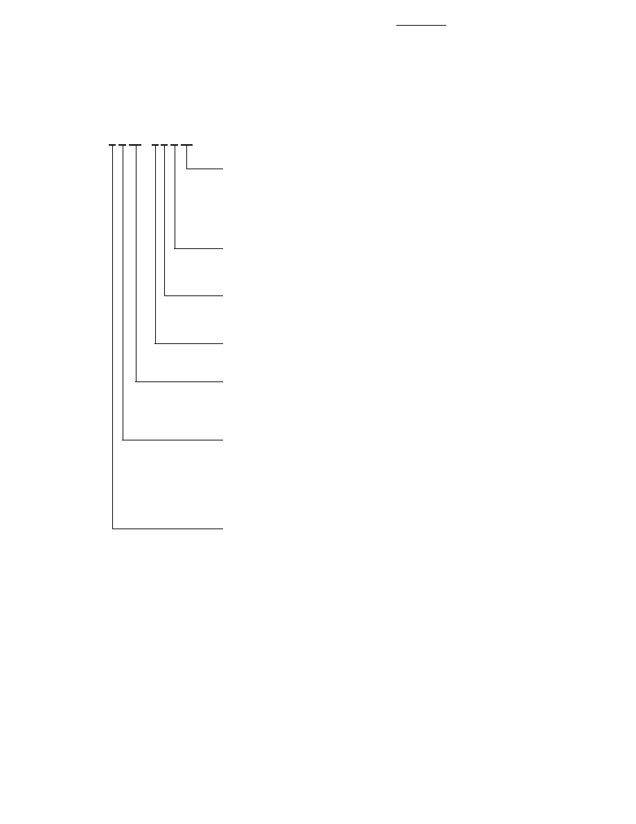
Part Numbering System
HLMP - C x xx - x x x xx
Mechanical Options
00: Bulk
01: Tape & Reel, Crimped Leads
02: Tape & Reel, Straight Leads
B2: Right Angle Housing, Even Leads
UQ: Ammo Pack, Horizontal Leads
Color Bin Options
0: Full Color Bin Distribution
D: Color Bins 4 & 5 only
Maximum Iv Bin Options
0: Open (No Maximum Limit)
Others: Please refer to the Iv Bin Table
Minimum Iv Bin Options
Please refer to the Iv Bin Table
Viewing Angle & Standoffs Options
15: 15 Degree, without Standoffs
17: 15 Degree, with Standoffs
23: 25 Degree, without Standoffs
Color Options
1. AS AlGaAs Red
2. High Efficiency Red
3. Yellow
4. Orange
5. Green
6. Emerald Green
Package Options
C: T-1 3/4 (5 mm)

4
Package Dimensions
Absolute Maximum Ratings at T
A
= 25
∞
C
High
High
Performance
DH AS
Efficiency
Green and
AlGaAs
Red and
Emerald
Parameter
Red
Orange
Yellow
Green
Units
DC Forward Current
[1]
30
30
20
30
mA
Transient Forward Current
[2]
500
500
500
500
mA
(10
µ
sec Pulse)
Reverse Voltage (Ir = 100
µ
A)
5
5
5
5
V
LED Junction Temperature
110
110
110
110
∞
C
Operating Temperature Range
≠20 to +100
≠55 to +100
≠20 to +100
∞
C
Storage Temperature Range
≠55 to +100
∞
C
Lead Soldering Temperature
260
∞
C for 5 seconds
[1.6 mm (0.063 in.) from body]
Notes:
1. See Figure 5 for maximum current derating vs. ambient temperature.
2. The transient current is the maximum nonrecurring peak current the device can withstand without damaging the LED die and wire
bond.
1.14 ± 0.20
(0.045 ± 0.008)
5.80 ± 0.20
(0.228 ± 0.008)
5.00 ± 0.20
(0.197 ± 0.008)
31.60
(1.244)
MIN.
0.70 (0.028)
MAX.
1.00
(0.039)
MIN.
8.71 ± 0.20
(0.343 ± 0.008)
2.54 ± 0.38
(0.100 ± 0.015)
0.50 ± 0.10
(0.020 ± 0.004)
SQ. TYP.
NOTES:
1. ALL DIMENSIONS ARE IN MILLIMETERS (INCHES).
2. LEADS ARE MILD STEEL, SOLDER DIPPED.
3. AN EPOXY MENISCUS MAY EXTEND ABOUT
0.5 mm (0.020 in.) DOWN THE LEADS.
CATHODE
LEAD
1.85 (0.073)
MAX.
CATHODE
FLAT
(NOTE 1)
HLMP-Cx15 and HLMP-Cx23
HLMP-Cx17
1.14 ± 0.20
(0.045 ± 0.008)
5.80 ± 0.20
(0.228 ± 0.008)
5.00 ± 0.20
(0.197 ± 0.008)
31.60
(1.244)
MIN.
0.70 (0.028)
MAX.
1.00
(0.039)
MIN.
8.71 ± 0.20
(0.343 ± 0.008)
2.54 ± 0.38
(0.100 ± 0.015)
0.50 ± 0.10
(0.020 ± 0.004)
SQ. TYP.
CATHODE
LEAD
CATHODE
FLAT
1.50 ± 0.15
(0.059 ± 0.006)
12.60 ± 0.18
(0.496 ± 0.007)
5
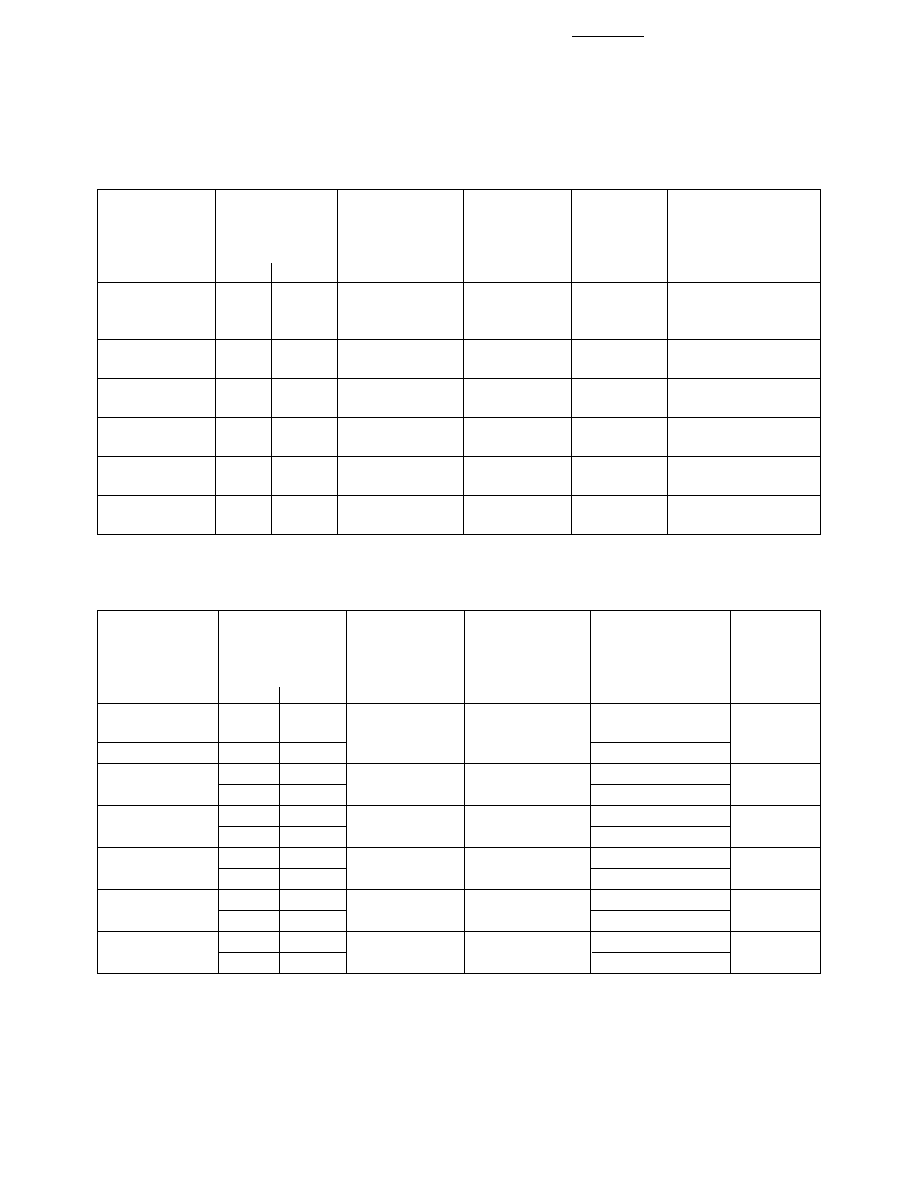
Optical Characteristics at T
A
= 25
∞
C
Luminous
Color,
Viewing
Intensity
Peak
Dominant
Angle
Luminous
Iv (mcd)
Wavelength
Wavelength
2
1/2
Efficacy
@ 20 mA
[1]
peak
(nm)
d
[2]
(nm)
(Degrees)
[3]
v
Part Number
Min.
Typ.
Typ.
Typ.
Typ.
(lm/w)
HLMP-C115
290
600
645
637
11
80
HLMP-C117
HLMP-C123
90
200
26
HLMP-C215
138
300
635
626
17
145
90
170
23
HLMP-C315
146
300
583
585
17
500
96
170
25
HLMP-C415
138
300
600
602
17
380
90
170
23
HLMP-C515
170
300
568
570
20
595
69
170
28
HLMP-C615
17
45
558
560
20
656
6
27
28
Notes:
1. The luminous intensity, Iv, is measured at the mechanical axis of the lamp package. The actual peak of the spatial radiation pattern
may not be aligned with this axis.
2. The dominant wavelength,
d
, is derived from the CIE Chromaticity Diagram and represents the color of the device.
3. 2
1/2
is the off-axis angle where the luminous intensity is 1/2 the on-axis intensity.
HLMP-C223
HLMP-C323
HLMP-C423
HLMP-C523
HLMP-C623
Electrical Characteristics at T
A
= 25
∞
C
Forward
Reverse
Capacitance
Speed of Response
Voltage
Breakdown
C (pF)
Thermal
s
(ns)
Vf (Volts)
Vr (Volts)
Vf = 0
Resistance
Time Constant
@ If = 20 mA
@ Ir = 100
µ
A
f = 1 MHz
R
J-PIN
e
-t/
s
Part Number
Typ.
Max.
Min.
Typ.
(
∞
C/W)
Typ.
HLMP-C115
1.8
2.2
5
30
210
30
HLMP-C117
HLMP-C123
HLMP-C215
1.9
2.6
5
11
210
90
HLMP-C223
HLMP-C315
2.1
2.6
5
15
210
90
HLMP-C323
HLMP-C415
1.9
2.6
5
4
210
280
HLMP-C423
HLMP-C515
2.2
3.0
5
18
210
260
HLMP-C523
HLMP-C615
2.2
3.0
5
18
210
260
HLMP-C623