 | –≠–ª–µ–∫—Ç—Ä–æ–Ω–Ω—ã–π –∫–æ–º–ø–æ–Ω–µ–Ω—Ç: HLMP-Cx08 | –°–∫–∞—á–∞—Ç—å:  PDF PDF  ZIP ZIP |
T-1
3
/
4
(5 mm) AlInGaP Lamps
Technical Data
HLMP-Cx08 Series
HLMP-Cx25 Series
HLMP-Cx27 Series
HLMP-C610
Features
∑ High Intensity
∑ General Purpose Leads
∑ Popular 5 mm Diameter
∑ Available in Bulk, Tape
and Reel, or Ammopack
∑ 8
∞
or 25
∞
Viewing Angles
∑ Choice of Colors:
Amber or Red
Applications
∑ Indoor/Outdoor Applications
∑ Small Store-front Signs
∑ Message Panels
∑ Road Construction Barrier
Lights
∑ Center High Mount Stop
Lights
∑ Spoiler, Car Decorative
Lighting
∑ Motorcycle/Bicycle Warning
Lights
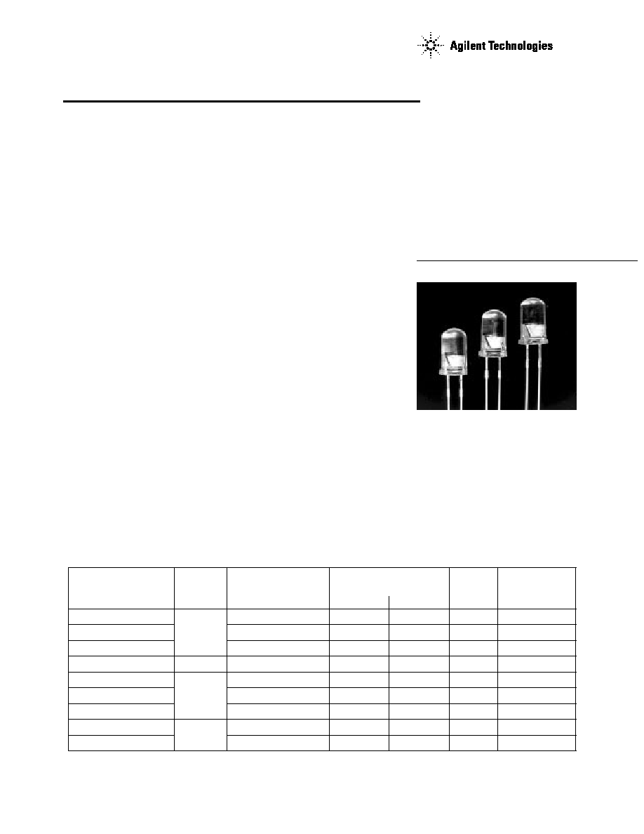
Description
The HLMP-Cx08, HLMP-Cx25,
HLMP-Cx27, and HLMP-C610
series are 5 mm lamps specially
designed for applications requir-
ing very high on-axis intensity
that is not achievable with a
standard lamp. These devices
are capable of producing light
output over a wide range of
drive currents.
Built using AlInGaP technology,
they are well suited for typical
5 mm TS-AlGaAs lamp applica-
tions, and have significantly
SUPERIOR RELIABILITY than
most TS-AlGaAs lamps in wet/
hot environments. These lamps
come with clear non-diffused
lens and are optically designed
to yield superior light output.
Device Selection
Typical Viewing Luminous Intensity,
Angle
[1]
(degrees), Iv (mcd) @ 20 mA
Dominant
Part Number
Standoff
2
1
/
2
Min.
Typ.
Color
Wavelength
[2]
HLMP-C008-U00xx
No
8
2900.0
6000.0
Red
626
HLMP-C208-S00xx
8
2600.0
3000.0
Amber
590
HLMP-C608-R00xx
8
1000.0
2000.0
Red
635
HLMP-C610-R00xx
Yes
8
1000.0
2000.0
Red
635
HLMP-C025-P00xx
No
25
500.0
1000.0
Red
626
HLMP-C225-O00xx
25
450.0
800.0
Amber
590
HLMP-C625-P00xx
25
500.0
700.0
Red
635
HLMP-C027-P00xx
Yes
25
500.0
1000.0
Red
626
HLMP-C627-P00xx
25
500.0
700.0
Red
635
Notes:
1.
1
/
2
is the off-axis angle at which the luminous intensity is half of the axial luminous intensity.
2. The dominant wavelength,
d
, is derived from the CIE chromaticity diagram and represents the single wavelength which defines the
color of the device.
2
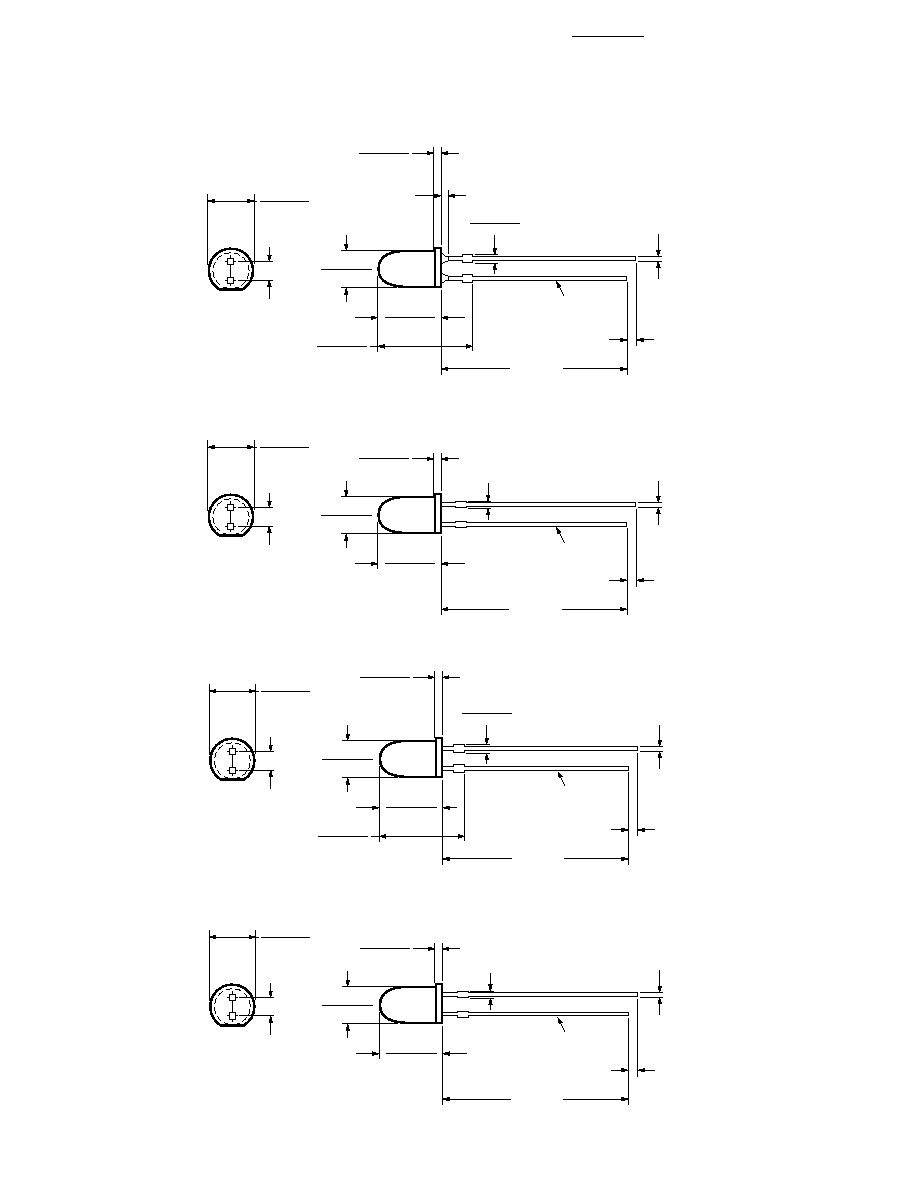
Package Dimensions
6.10 (0.240)
5.46 (0.215)
1.27
(0.050)
MIN.
2.54
(0.100)
0.45
(0.018)
SQ. NOM.
CATHODE
LEAD
25.40
(1.000)
MIN.
NOM.
5.21 (0.205)
4.70 (0.105)
13.50 (0.53)
13.30 (0.52)
1.07 (0.042)
0.56 (0.022)
1.00 (0.040)
MAX. EPOXY
MENISCUS
9.14 (0.360)
8.36 (0.330)
1.32 (0.052)
1.02 (0.040)
6.10 (0.240)
5.46 (0.215)
1.27
(0.050)
MIN.
2.54
(0.100)
0.45
(0.018)
SQ. NOM.
CATHODE
LEAD
25.40
(1.000)
MIN.
NOM.
5.21 (0.205)
4.70 (0.105)
1.07 (0.042)
0.56 (0.022)
9.14 (0.360)
8.36 (0.330)
1.02 (0.004)
MAX. TYP.
HLMP-Cx27
HLMP-Cx25
6.10 (0.240)
5.46 (0.215)
1.27
(0.050)
MIN.
2.54
(0.100)
0.45
(0.018)
SQ. NOM.
CATHODE
LEAD
25.40
(1.000)
MIN.
NOM.
5.08 (0.200)
4.57 (0.100)
13.55 (0.533)
13.35 (0.525)
0.89 (0.035)
0.64 (0.023)
9.19 (0.362)
8.43 (0.332)
1.32 (0.052)
1.02 (0.040)
6.10 (0.240)
5.46 (0.215)
1.27
(0.050)
MIN.
2.54
(0.100)
0.45
(0.018)
SQ. NOM.
CATHODE
LEAD
25.40
(1.000)
MIN.
NOM.
5.08 (0.200)
4.57 (0.100)
0.89 (0.035)
0.64 (0.023)
9.19 (0.362)
8.43 (0.332)
1.02 (0.004)
MAX. TYP.
HLMP-C610
HLMP-Cx08
3
Absolute Maximum Ratings at T
A
=25
∞
C
Parameter
Absolute Maximum
Units
Peak Forward Current
70
mA
Average Forward Current
[1]
30
mA
DC Current
[2]
50
mA
Reverse Voltage (I
R
= 100
µ
A)
5
V
LED Junction Temperature
110
∞
C
Operating Temperature
-40 to +100
∞
C
Storage Temperature
-40 to +120
Lead Soldering Temperature
260
∞
C for 5 seconds
[1.59 mm (0.060 in.) below seating plane]
Notes:
1. See Figure 2 to establish pulsed operating conditions.
2. Derate linearly from 50
∞
C at 0.5 mA/
∞
C.
3. The transient peak current is the maximum non-recurring peak current that can be applied to the device without damaging
the LED die and wirebond. It is not recommended that this device be operated at peak currents above the Absolute Maximum
Peak Forward Current.
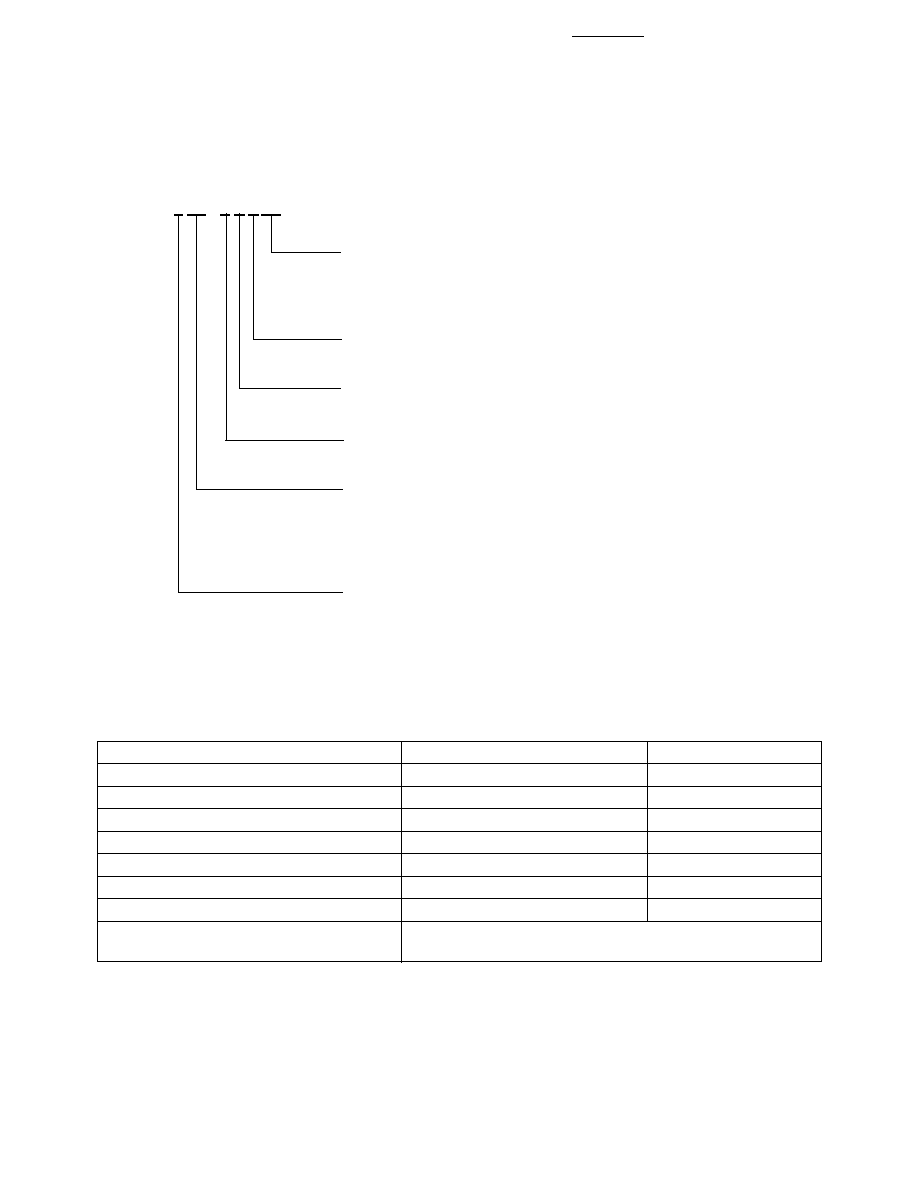
Part Numbering System
HLMP - C x xx - x x x xx
Mechanical Option
00: Bulk
02: Tape & Reel, Straight Leads
DD: Ammo Pack
Color Bin Options
0: Full Color Bin Distribution
Maximum Iv Bin Options
0: Open (no max. limit)
Minimum Iv Bin Options
Please refer to the Iv Bin Table
Viewing Angle & Standoff Option
08: 8 degrees, without standoff
10: 8 degrees, with standoff
25: 25 degrees, without standoff
27: 25 degrees, with standoff
Color Options
0: AlInGaP Red 626 nm
2: AlInGaP Amber 590 nm
6: AlInGaP Red 635 nm
4
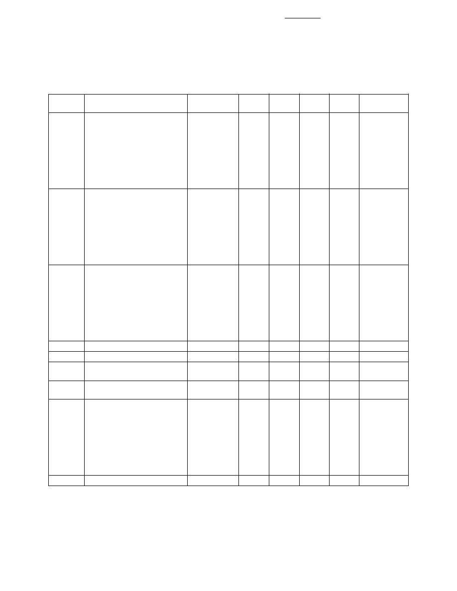
Optical/Electrical Characteristics at T
A
=25
∞
C
Test
Symbol
Parameter
Device
Min.
Typ.
[3]
Max.
Units
Conditions
2
1
/
2
Included Angle Between Half
HLMP-C008
8
Deg.
I
F
= 20 mA
Luminous Intensity Points
[1]
HLMP-C208
8
See Note 1
HLMP-C608
8
HLMP-C025
25
HLMP-C225
25
HLMP-C625
25
HLMP-C610
8
HLMP-C027
25
HLMP-C627
25
d
Dominant Wavelength
[2]
HLMP-C008
626
nm
See Note 2
HLMP-C208
590
HLMP-C608
635
HLMP-C025
626
HLMP-C225
590
HLMP-C625
635
HLMP-C610
635
HLMP-C027
626
HLMP-C627
635
PEAK
Peak Wavelength
HLMP-C008
635
nm
Measurement
HLMP-C208
594
at Peak
HLMP-C608
650
HLMP-C025
635
HLMP-C225
594
HLMP-C625
650
HLMP-C610
650
HLMP-C027
635
HLMP-C627
650
1
/
2
Spectral Line Halfwidth
17
nm
s
Speed of Response
20
ns
C
Capacitance
40
pF
V
F
= 0;
f = 1 MHz
R
J-PIN
Thermal Resistance
260
∞
C/W
Junction to
Cathode Lead
V
F
Forward Voltage
HLMP-C008
1.9
2.4
V
I
F
= 20 mA
HLMP-C208
1.9
2.6
HLMP-C608
1.9
2.6
HLMP-C025
1.9
2.4
HLMP-C225
1.9
2.6
HLMP-C625
1.9
2.6
HLMP-C610
1.9
2.6
HLMP-C027
1.9
2.4
HLMP-C627
1.9
2.6
V
R
Reverse Breakdown Voltage
5.0
V
I
R
= 100
µ
A
Notes:
1.
1
/
2
is the off-axis angle at which the luminous intensity is half of the axial luminous intensity.
2. The dominant wavelength,
d
, is derived from the CIE chromaticity diagram and represents the single wavelength which defines the
color of the device.
3. Typical specification for reference only. Do not exceed absolute maximum ratings.
5
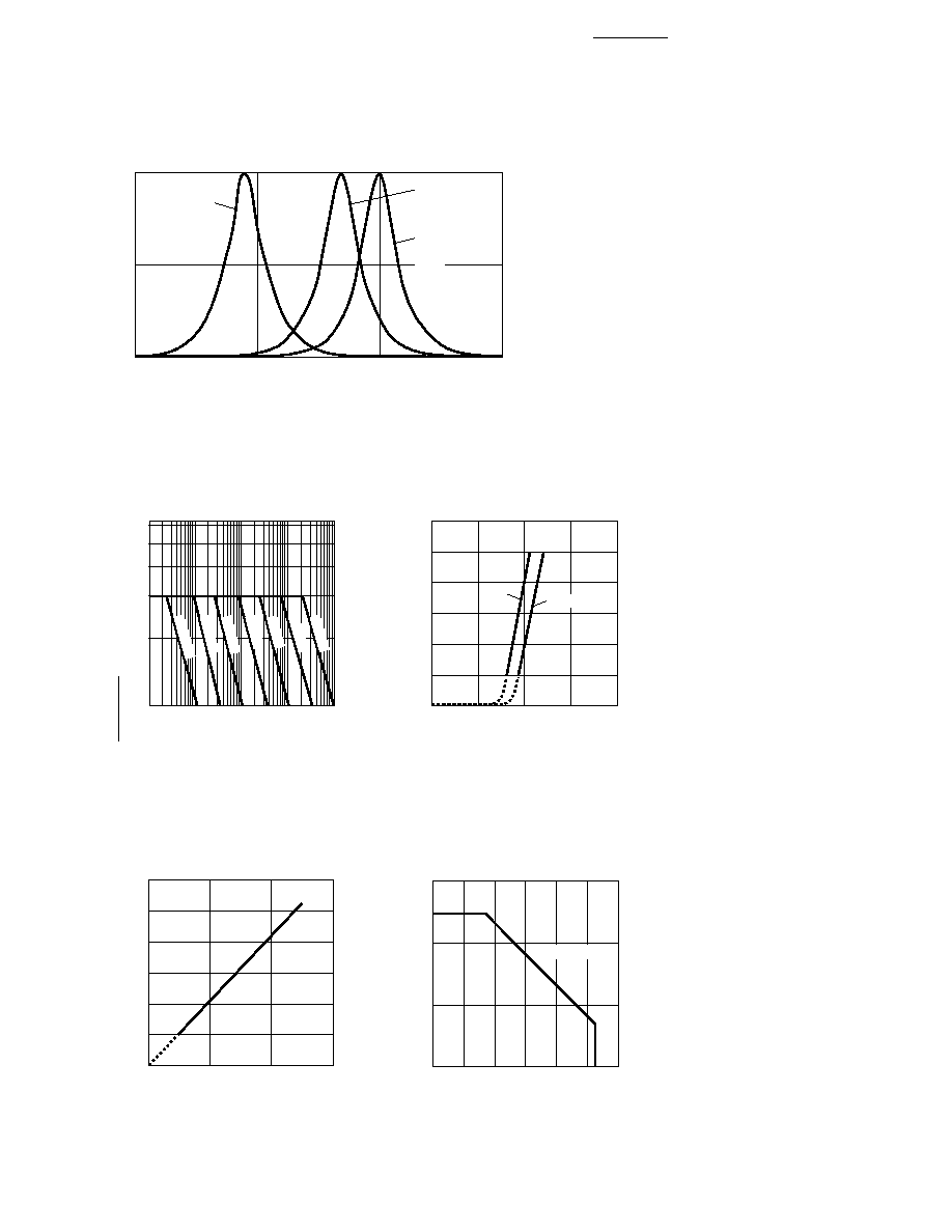
Figure 1. Relative Intensity vs. Wavelength.
Figure 2. Maximum Tolerable Peak
Current vs. Pulse Duration.
Figure 3. Forward Current vs.
Forward Voltage.
Figure 4. Relative Luminous Intensity
vs. Forward Current.
RATIO OF MAXIMUM TOLERABLE
PEAK CURRENT TO MAXIMUM
TOLERABLE DC CURRENT
1.0
10,000
6
1
tp ≠ PULSE DURATION ≠ µs
1000
5
3
100
10
4
2
I PEAK
≠ MAX.
I DC
≠ MAX.
100 KHz
30 KHz
10 KHz
3 KHz
1 KHz
300 Hz
100 Hz
CURRENT ≠ mA
1.0
0
VF ≠ FORWARD VOLTAGE ≠ V
50
40
30
10
2.0
3.0
60
1.5
2.5
20
RED
AMBER
RELATIVE LUMINOUS INTENSITY
(NORMALIZED AT 20 mA)
0
0
IF ≠ DC FORWARD CURRENT ≠ mA
2.5
2.0
1.5
0.5
60
3.0
20
40
1.0
WAVELENGTH ≠ nm
RELATIVE INTENSITY
550
600
650
700
1.0
0.5
0
C208
C225
C008
C025
C027
C608
C625
C627
C610
Figure 5. Maximum Forward DC
Current vs. Ambient Temperature.
FORWARD CURRENT (mA)
0
0
AMBIENT TEMPERATURE (∞C)
40
120
60
20
40
20
60
80
100
R
J-A = 780∞C/W