 | –≠–ª–µ–∫—Ç—Ä–æ–Ω–Ω—ã–π –∫–æ–º–ø–æ–Ω–µ–Ω—Ç: HLMP-MD16 | –°–∫–∞—á–∞—Ç—å:  PDF PDF  ZIP ZIP |
Agilent HLMP-LD16/HLMP-MD16
4 mm Precision Optical Performance
Red Oval LEDs
Data Sheet
Features
∑ High brightness material
AlInGaP
630 mm Red
∑ Viewing angles:
major axis 100
∞
minor axis 50
∞
∑ Well defined spatial radiation
pattern
∑ Superior resistance to moisture
Applications
∑ Commercial outdoor advertising
∑ Full color signs
Description
These Precision Optical
Performance Oval LEDs are
specifically designed for Full
Color/Video and Passenger Infor-
mation signs. The oval shaped
radiation pattern (50
∞
x 100
∞
) and
high luminous intensity ensure
that these devices are excellent
for wide field of view outdoor
applications where a wide view-
ing angle and readability in
sunlight are essential. These
lamps have very smooth, matched
radiation patterns ensuring
consistent color mixing in full
color applications, message
uniformity across the viewing
angle of the sign.
High efficiency LED materials are
used in these lamps: Aluminum
Indium Gallium Phosphide
(AlInGaP) for Red color. The
higher performance AlInGaP II is
used. Each lamp is made with an
advanced optical grade epoxy
offering superior high tempera-
ture and high moisture resistance
in outdoor applications. The
package epoxy contains both
UV-a and UV-b inhibitors to
reduce the effects of long term
exposure to direct sunlight.
Designers can select parallel
(where the axis of the leads is
parallel to the wide axis of the
oval radiation pattern) or perpen-
dicular orientation. Both of the
lamps are red diffused-tinted.

2
Package Dimensions
Notes:
1. The luminous intensity is measured on the mechanical axis of the lamp package.
2. The optical axis is closely aligned with the package mechanical axis.
3. The dominant wavelength,
d
, is derived from the CIE Chromaticity Diagram and represents the color of the lamp.
Device Selection Guide AlInGaP2
Color
Luminous
Dominant
Intensity
Wavelength
I
V
(mcd) at 20 mA
Tinting
Leadframe
Package
Part Number
d
(nm) Typ.
Min. Max.
Type
Orientation
Drawing
HLMP-MD16-MQ000
Red 630
450 1730
Red
Perpendicular
A
HLMP-MD16-MQT00
Red 630
450 1730
Red
Perpendicular
A
HLMP-LD16-MQ000
Red 630
450 1730
Red
Parallel
B
HLMP-LD16-MQT00
Red 630
450 1730
Red
Parallel
B
HLMP-MD16-LP000
Red 630
345 1330
Red
Perpendicular
A
HLMP-MD16-LPT00
Red 630
345 1330
Red
Perpendicular
A
HLMP-LD16-LP000
Red 630
345 1330
Red
Parallel
B
HLMP-LD16-LPT00
Red 630
345 1330
Red
Parallel
B
3.70 ± 0.20
(0.146 ± 0.008)
1.25 ± 0.20
(0.049 ± 0.008)
0.80
(0.016)
MAX. EPOXY MENISCUS
9.80 ± 0.18
(0.386 ± 0.007)
CATHODE
LEAD
A
6.30 ± 0.20
(0.248 ± 0.020)
2.54 ± 0.30
(0.100 ± 0.012)
21.00
(0.827)
MIN.
1.00
(0.039)
MIN.
0.40
+0.10
≠0
(0.016
+0.004
≠0.000)
0.45
+0.10
≠0.04
(0.018
+0.004
≠0.002)
3.70 ± 0.20
(0.146 ± 0.008)
1.25 ± 0.20
(0.049 ± 0.008)
0.80
(0.016)
MAX. EPOXY MENISCUS
9.80 ± 0.18
(0.386 ± 0.007)
CATHODE
LEAD
B
6.30 ± 0.20
(0.248 ± 0.008)
2.54 ± 0.30
(0.100 ± 0.012)
21.00
(0.827)
MIN.
1.00
(0.039)
MIN.
0.40
+0.10
≠0
(0.016
+0.004
≠0.000)
0.45
+0.10
≠0.04
(0.018
+0.004
≠0.002)
Notes:
1. Dimensions in millimeters (inches).
2. Tolerance ± 0.1 mm unless otherwise noted.
3
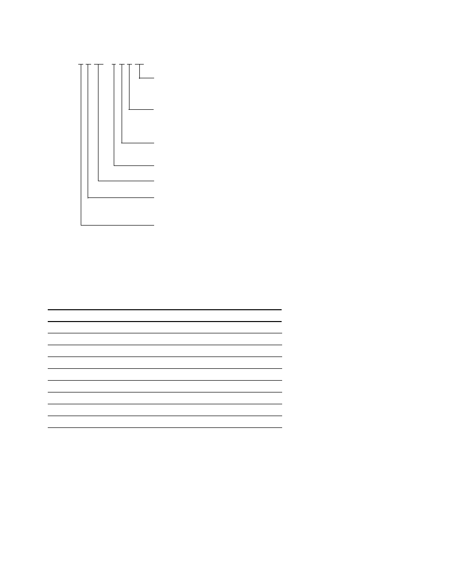
Part Numbering System
HLMP - x x xx - x x x xx
Mechanical Options
00: Bulk Packaging
DD: Ammo Pack
Color Bin and V
F
Selections
0: No Color Bin Limitation
T: Red Color with max V
F
of 2.6V
Maximum Intensity Bin
0: No Iv Bin Limitation
Minimum Intensity Bin
Refer to Device Selection Guide
Color
D: 630 nm Red
Package
L: 4mm 50∫ x 100∫ Oval, Parallel
M: 4mm 50∫ x 100∫ Oval, Perpendicular
Absolute Maximum Ratings
T
A
= 25
∞
C
Parameter
AlInGaP Value
Units
DC Forward Current
[1]
50
mA
Peak Forward Current
100
mA
Average Forward Current
30
mA
Power Dissipation
120
mW
Reverse Voltage (I
R
= 100
µ
A)
5
V
LED Junction Temperature
130
∞
C
Operating Temperature Range
≠40 to +100
∞
C
Storage Temperature Range
≠40 to +120
∞
C
Soldering Temperature
260 for 5 sec
∞
C
Note:
1. Derate linearly as shown in Figure 3 for temperatures above 50
∞
C.

4
Electrical/Optical Characteristics
T
A
= 25
∞
C
Parameter
Symbol
Min.
Typ.
Max.
Units
Test Conditions
Typical Viewing Angle
Major
2
1/2
100
deg
Minor
50
Forward Voltage
Red (
d
= 630 nm)
V
F
2.0
2.4
[1]
V
I
F
= 20 mA
Reverse Voltage
Red
V
R
5
20
V
I
R
= 100
µ
A
Peak Wavelength
Peak of Wavelength of Spectral
Red (
d
= 630 nm)
peak
639
nm
Distribution at I
F
= 20 mA
Spectral Halfwidth
Wavelength Width at Spectral
Red (
d
= 630 nm)
1/2
17
nm
Distribution Power Point
at I
F
= 20 mA
Capacitance
Red
C
40
pF
V
F
= 0, F = 1 MHz
Thermal Resistance
R
J-PIN
240
∞
C/W
LED Junction-to-Cathode Lead
Luminous Efficacy
Emitted Luminous Power/
Red (
d
= 630 nm)
v
155
lm/W
Emitted Radiant Power
Notes:
1. For option -xxTxx, maximum forward voltage, V
F
is 2.6V.
2. 2
1/2
is the off-axis angle where the luminous intensity is 1/2 the on-axis intensity.
3. The radiant intensity, I
e
in watts per steradian, may be found from the equation I
e
= I
v
/
v
where I
v
is the luminous intensity in candelas and
v
is
the luminous efficacy in lumens/watt.
5
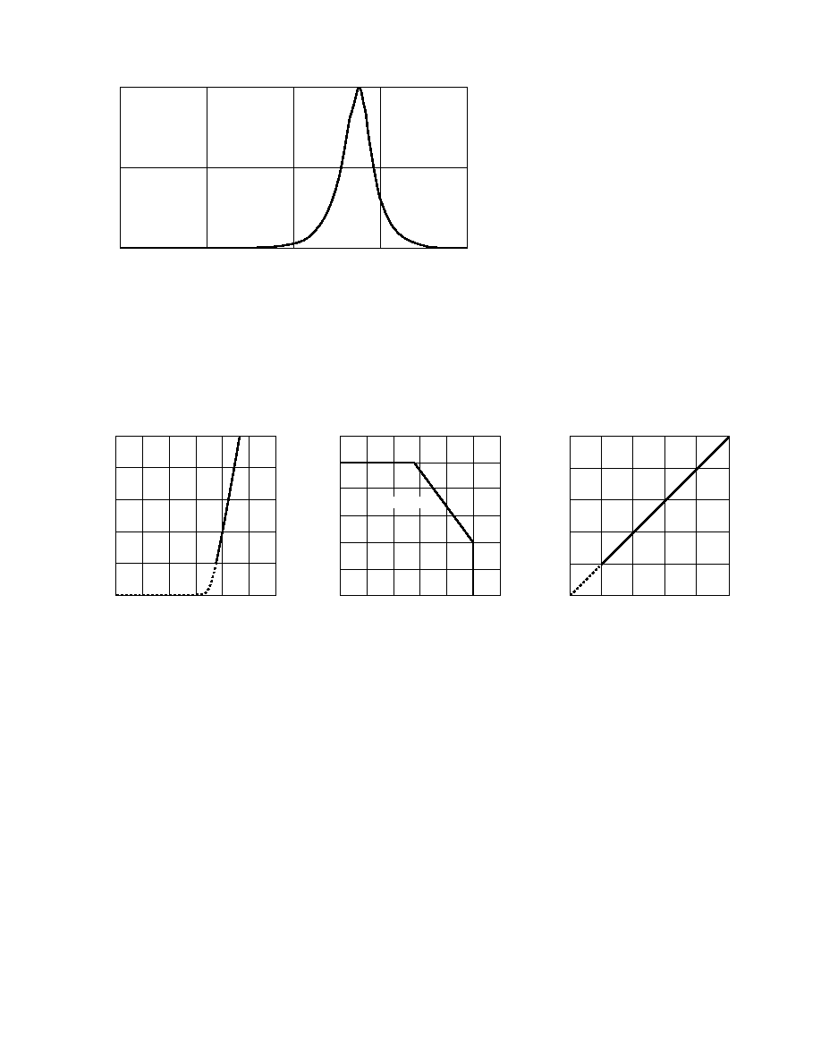
Figure 3. AlInGaP maximum forward current
vs. ambient temperature.
Figure 1. Relative intensity vs. wavelength.
Figure 2. AlInGaP forward current vs.
forward voltage.
Figure 4. AlInGaP relative luminous intensity
vs. forward current.
WAVELENGTH ≠ nm
RELATIVE INTENSITY
1.0
0.5
0
600
700
500
650
550
0
40
20
I F
≠ FORWARD CURRENT ≠ mA
VF ≠ FORWARD VOLTAGE ≠ V
0
3.0
1.5
2.0
2.5
10
30
50
1.0
0.5
RELATIVE LUMINOUS INTENSITY
(NORMALIZED AT 20 mA)
0
0
IF ≠ FORWARD CURRENT ≠ mA
20
40
2.0
1.0
50
0.5
1.5
2.5
30
10
I F
≠ FORWARD CURRENT ≠ mA
0
0
TA ≠ AMBIENT TEMPERATURE ≠ ∞C
40
80
50
40
30
20
10
20
60
100
60
120
R
JA = 780∞C/W