 | –≠–ª–µ–∫—Ç—Ä–æ–Ω–Ω—ã–π –∫–æ–º–ø–æ–Ω–µ–Ω—Ç: HSMx-C265 | –°–∫–∞—á–∞—Ç—å:  PDF PDF  ZIP ZIP |
Agilent HSMx-C265
Surface Mount Chip LEDs
Data Sheet
Description
The HSMx-C265 is a reverse mount-
able chip-type LED for lighting the
non-component side of a PCB
board. In this reverse mounting
configuration, this LED is designed
to emit light through a small cut-out
hole in the PC board.
Features
∑ Reverse mountable
∑ Undiffused optics
∑ Small 3.4 x 1.25 mm footprint
∑ Operating temperature range of
≠30
∞
C to +85
∞
C
∑ Compatible with IR solder reflow
∑ Four colors available: red, orange,
yellow, and green
∑ Available in 8 mm tape on
7" (178 mm) diameter reels
Applications
∑ Keypad backlighting
∑ Symbol backlighting
∑ LCD backlighting
∑ Status indication
∑ Front panel indicator
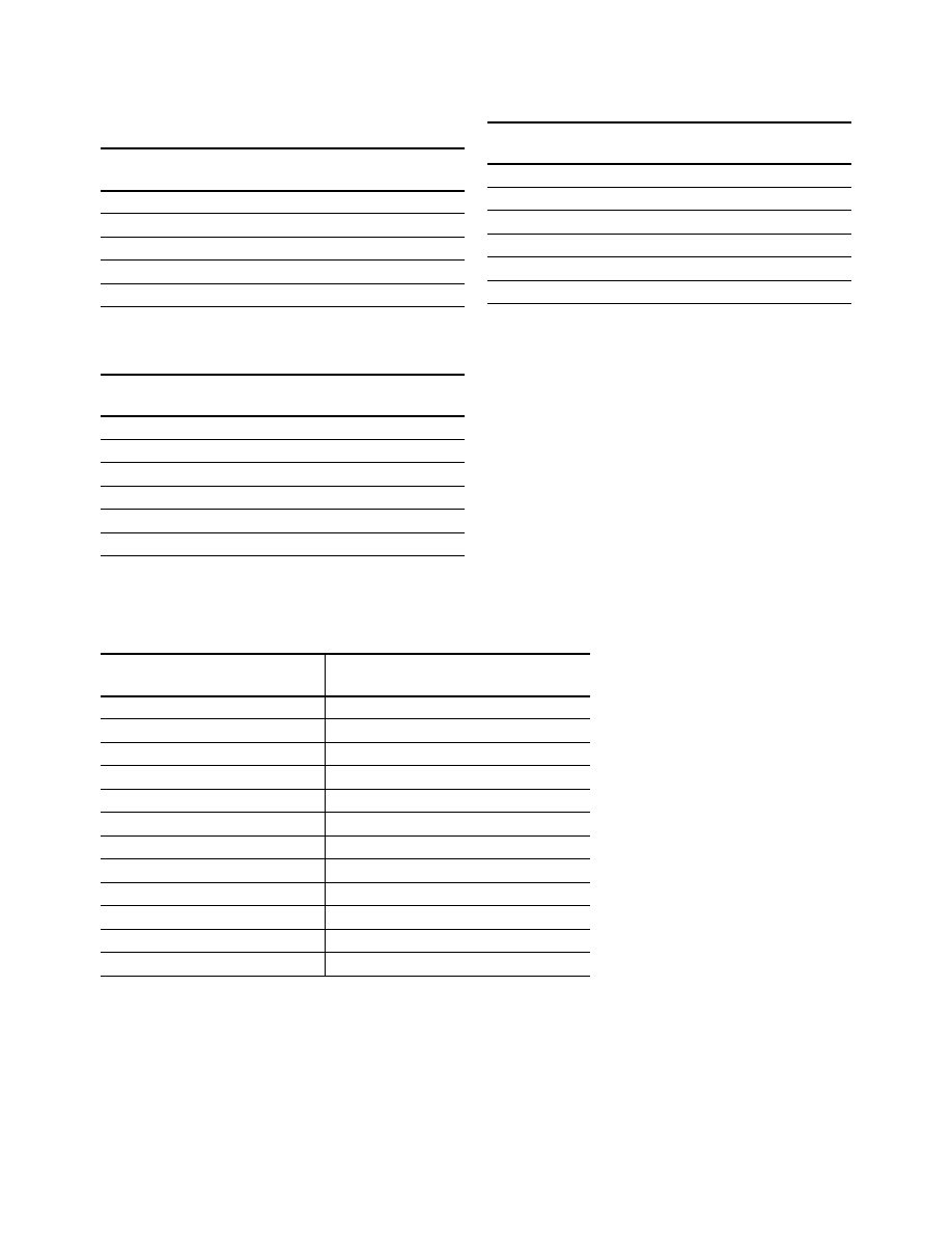
Device Selection Guide
Part Number
Color
Parts Per Reel
HSMS-C265
High Efficiency Red
3000
HSMD-C265
Orange
3000
HSMY-C265
Yellow
3000
HSMG-C265
Green
3000
HSMH-C265
AlGaAs Red
3000
The HSMx-C265 is available in
four colors. The small size, narrow
footprint, and low profile make
this series of LEDs excellent for
backlighting, status indication,
and front panel illumination
application.

2
Package Dimensions
Absolute Maximum Ratings
T
A
= 25
∞
C
Parameter
HSMD/G/S/Y-C265
HSMH-C265
Units
DC Forward Current
[1]
25
25
mA
Peak Pulsing Current
[2]
100
100
mA
Power Dissipation
65
65
mW
Reverse Voltage (I
R
= 100
µ
A)
5
5
V
LED Junction Temperature
95
95
∞
C
Operating Temperature Range
≠30 to +85
≠30 to +85
∞
C
Storage Temperature Range
≠40 to +85
≠40 to +85
∞
C
Soldering Temperature
See IR soldering profile (Figure 6)
Notes:
1. Derate linearly as shown in Figure 4.
2. Pulse condition of 1/10 duty and 0.1 ms width.
3.4 (0.134)
0.3 (0.012)
0.50 ± 0.15
(0.020 ± 0.006)
1.1 (0.043)
POLARITY
[3]
CATHODE
MARK (ETCHED)
[ANODE MARK FOR HSMH-C265]
1.1 (0.043)
0.50 ± 0.15
(0.020 ± 0.006)
1.2
(0.047)
1.25 (0.049)
LED DIE
UNDIFFUSED
EPOXY
PC BOARD
NOTES:
1. ALL DIMENSIONS IN MILLIMETERS (INCHES).
2. TOLERANCE IS ± 0.1 mm (± 0.004 IN.) UNLESS OTHERWISE SPECIFIED.
3. POLARITY OF HSMH-C265 WILL BE THE OPPOSITE OF WHAT IS SHOWN
ON ABOVE DRAWING.
SOLDERING
TERMINAL
2 ≠ 0.6 (0.028)
(GREEN SOLDER MASK)
CATHODE LINE
3
Electrical Characteristics
T
A
= 25
∞
C
Forward Voltage
Reverse Breakdown
Capacitance
Thermal
V
F
(Volts)
V
R
(Volts)
C (pF), VF = 0,
Resistance
@ I
F
= 20 mA
@ I
R
= 100
µ
A
f = 1 MHz
R
J-PIN
(
∞
C/W)
Part Number
Typ.
Max.
Min.
Typ.
[1]
Typ.
HSMS-C265
2.1
2.6
5
8
250
HSMD-C265
2.2
2.6
5
6
250
HSMY-C265
2.1
2.6
5
7
250
HSMG-C265
2.2
2.6
5
6
250
HSMH-C265
1.8
2.6
5
18
300
Optical Characteristics
T
A
= 25
∞
C
Luminous Intensity
Peak Wavelength
Dominant Wavelength
Viewing Angle
I
v
(mcd) @ 20 mA
[1]
peak
(nm)
d
(nm)
[2]
2
1/2
Degrees
[3]
Part Number
Color
Min.
Typ.
Typ.
Typ.
Typ.
HSMS-C265
HER
2.5
10.0
630
626
170
HSMD-C265
Orange
2.5
8.0
605
604
170
HSMY-C265
Yellow
2.5
8.0
589
586
170
HSMG-C265
Green
4.0
15.0
570
572
170
HSMH-C265
AlGaAs
6.3
17.0
660
639
170
Notes:
1. The luminous intensity, I
v
, is measured at the peak of the spatial radiation pattern which may not be aligned with the mechanical axis of the
lamp package.
2. The dominant wavelength,
d
, is derived from the CIE Chromatically Diagram and represents the perceived color of the device.
3.
1/2
is the off-axis angle where the luminous intensity is 1/2 the peak intensity.
4
Light Intensity (Iv) Bin Limits
[1]
Intensity (mcd)
Intensity (mcd)
Bin ID
Min.
Max.
Bin ID
Min.
Max.
A
0.11
0.18
N
28.50
45.00
B
0.18
0.29
P
45.00
71.50
C
0.29
0.45
Q
71.50
112.50
D
0.45
0.72
R
112.50
180.00
E
0.72
1.10
S
180.00
285.00
F
1.10
1.80
T
285.00
450.00
G
1.80
2.80
U
450.00
715.00
H
2.80
4.50
V
715.00
1125.00
J
4.50
7.20
W
1125.00
1800.00
K
7.20
11.20
X
1800.00
2850.00
L
11.20
18.00
Y
2850.00
4500.00
M
18.00
28.50
Note:
1. Bin categories are established for classification of products. Products may not be available in all
categories. Please contact your Agilent representative for information on currently available bins.
Orange Color Bins
[1]
Dom. Wavelength (nm)
Bin ID
Min.
Max.
A
597.0
600.0
B
600.0
603.0
C
603.0
606.0
D
606.0
609.0
E
609.0
612.0
F
612.0
615.0
Yellow/Amber Color Bins
[1]
Dom. Wavelength (nm)
Bin ID
Min.
Max.
A
582.0
584.5
B
584.5
587.0
C
587.0
589.5
D
589.5
592.0
E
592.0
594.5
F
594.5
597.0
Color Bin Limits
Green Color Bins
[1]
Dom. Wavelength (nm)
Bin ID
Min.
Max.
A
561.5
564.5
B
564.5
567.5
C
567.5
570.5
D
570.5
573.5
E
573.5
576.5
Tolerance:
±
0.5 nm
Tolerance:
±
1 nm
Tolerance:
±
0.5 nm
Tolerance:
±
15%

5
WAVELENGTH ≠ nm
HER
GREEN
RELATIVE INTENSITY
1.0
0.5
0
500
550
600
650
700
750
YELLOW
ORANGE
Figure 2. Forward current vs. forward
voltage.
Figure 3. Luminous intensity vs. forward
current.
Figure 4. Maximum forward current vs.
ambient temperature.
Figure 5. Relative intensity vs. angle.
100
10
1
0.1
1.5
1.7
1.9
2.1
2.3
VF ≠ FORWARD VOLTAGE ≠ V
I F
≠ FORWARD CURRENT ≠ mA
GREEN
HER
ORANGE
YELLOW
0
10
20
40
IF ≠ FORWARD CURRENT ≠ mA
0
0.4
1.2
1.6
LUMINOUS INTENSITY
(NORMALIZED AT 20 mA)
30
0.8
0
35
0
20
60
80
100
5
I F MAX.
≠ MAXIMUM FORWARD CURRENT ≠ mA
TA ≠ AMBIENT TEMPERATURE ≠ ∞C
40
15
25
30
10
R
J-A = 600∞C/W
20
R
J-A = 800∞C/W
Note:
1. All dimensions in millimeters (inches).
RELATIVE INTENSITY ≠ %
1.00
0
ANGLE
0.80
0.60
0.50
0.70
0.20
0.10
0.30
0.40
0.90
-70
-50
-30
0
20 30
50
70
90
-90
-20
-80
-60
-40
-10
10
40
60
80
Figure 1. Relative intensity vs. wavelength.