 | –≠–ª–µ–∫—Ç—Ä–æ–Ω–Ω—ã–π –∫–æ–º–ø–æ–Ω–µ–Ω—Ç: LSC2500 | –°–∫–∞—á–∞—Ç—å:  PDF PDF  ZIP ZIP |
Document Outline
- Features
- Applications
- Description
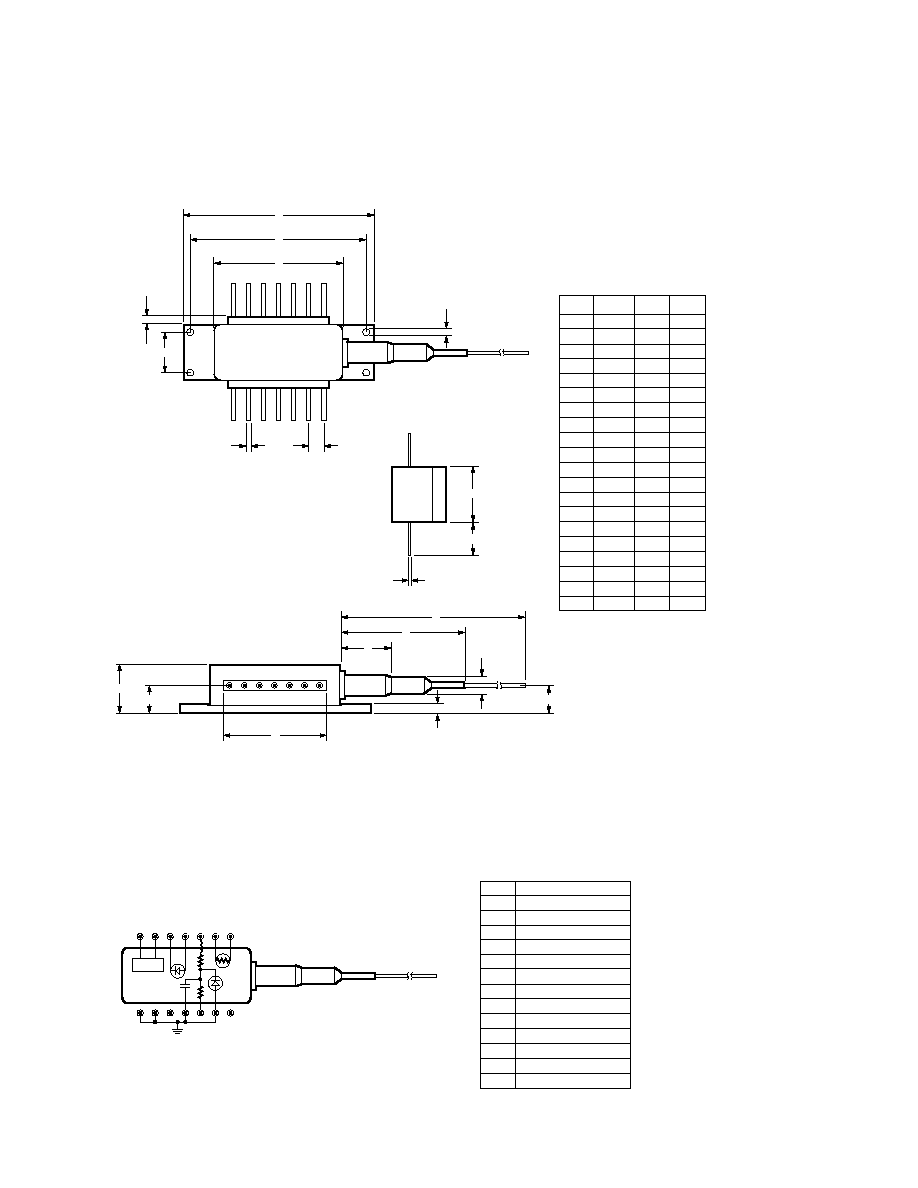
- LSC2500 Mechanical Outline
- LSC2500 Pin Connections and Block Diagram
- LSC2500 Typical Operating Characteristics
- Absolute Maximum Ratings at +25∞C
- Performance Specifications Ö Laser [1]
- Performance Specifications Ö Monitor Photodiode
- Thermistor
- TEC
- Fiber Pigtail: Tight jacketed, self-mode stripping, single mode fiber
- Ordering Information
- Handling Precautions
- CDRH Certification
- Laser Warning

559
2.488 Gb/s DFB Laser Module
with Integral Optical Isolator
Technical Data
LSC2500
Features
∑ Center Wavelength Between
1535 nm and 1565 nm
∑ Modulation Capability up to
2.488 Gb/s
∑ 30 dB Internal Optical
Isolation
∑ 25
Impedance Matched
∑ Wide Operating
Temperature Range: -20
∞
C to
+65
∞
C
∑ Industry Standard Hermetic
14 PIN Butterfly Package
Applications
∑ Telecommunications
∑ Fiber Optic Sensors
∑ Cable Television
∑ Military Communications
and Control Systems
∑ Instrumentation
Description
LSC2500 laser modules are
highly reliable fiber optic light
sources operating in the
1550 nanometer band. The
internal DFB lasers are based
upon InGaAs ridge waveguide
Multi Quantum Well technology
and fabricated by the Metal
Organic Vapor Phase Epitaxy
(MOVPE) process, resulting in
long lifetimes and modest
threshold currents.
The LSC2500 package includes a
photodiode for monitoring the
laser output, a thermistor for
monitoring laser heatsink
temperature, and a Peltier effect
thermoelectric cooler (TEC). A
heatsink mounting flange is
incorporated into the industry
standard 14 PIN package.
The LSC2500 also has 30 dB of
optical isolation which is
temperature controlled to
maintain isolation over the full
operating temperature range.
Laser Safety Warning
This device is a Class IIIb (3b) Laser Product. It may emit invisible laser radiation if operated with the fiber pigtail disconnected. To avoid
possible eye damage do not look into an unconnected fiber pigtail during laser operation. Do not exceed specified operating limits.
5965-8213E (4/97)
560
MIN.
29.6
20.6
12.45
8.4
≠
≠
5.40
≠
≠
≠
≠
≠
1500.00
≠
4.5
8.8
25.9
2.50
≠
≠
A
B
C
D
E
F
G
H
I
J
K
L
M
N
P
R
S
T
U
V
DIM.
U
A
I
MAX.
30.4
21.1
12.95
9.0
≠
≠
5.90
≠
≠
≠
≠
≠
≠
≠
6.5
9.0
26.1
2.70
≠
≠
≠
≠
≠
≠
0.75
12.0
≠
2.54
0.50
0.20
7.0
30.0
≠
2.0
≠
≠
≠
≠
0.75
17.8
NOM.
ALL DIMENSIONS IN MILLIMETERS
S
B
R
H
T
C
F
J
V
M
D
K
G
E
N
P
L
LSC2500 Mechanical Outline
Top View
LSC2500 Pin Connections and Block Diagram
Top View
Side View
Back View
TEC
7 6
5 4
3
2 1
8 9 10 11 12 13 14
THERMISTOR
THERMISTOR
LASER DC BIAS
MONITOR ANODE
MONITOR CATHODE
TEC
TEC
GROUND
GROUND
NOT CONNECTED
GROUND
LASER MODULATION
GROUND
NOT CONNECTED
1
2
3
4
5
6
7
8
9
10
11
12
13
14
PIN CONNECTIONS

561
LSC2500 Typical Operating Characteristics
0
4.5
0
10
40
60
100
5.0
1.5
LASER VOLTS (V)
DRIVE CURRENT (mA)
30
20
50
4.0
3.5
3.0
2.5
2.0
1.0
0.5
70 80 90
0
-10
-30
1000
4000
6000 7000
0
-20
REL. POWER (dB)
FREQUENCY (MHz)
3000
2000
5000
0
3500
0
10
40
60
100
4000
500
FIBER POWER (µW)
DRIVE CURRENT (mA)
30
20
50
3000
2500
2000
1500
1000
70 80 90
0
3500
0
200
600
1000
1600
4000
500
FIBER POWER (µW)
MONITOR CURRENT (µA)
400
800
3000
2500
2000
1500
1000
1200 1400
1534
70
0
1536
1540
1542
1544
100
90
30
20
REL. POWER (dB)
WAVELENGTH (nm)
1538
50
80
60
40
10
1546
1548
1550
1552
1556
1554
PRODUCT TYPE
: LSC2500
MODULATION BIT RATE
: 2.488 Gb/s
MODULATION DEPTH
: 12% EXTINCTION RATIO
THRESHOLD CURRENT (Ith)
mA
16.00
FORWARD VOLTAGE AT 3000
µ
W
V
2.26
POWER AT Ith + 40 mA
µ
W
1956.00
MONITOR CURRENT AT 2000
µ
W
µ
A
629.39
PEAK WAVELENGTH (12% XR)
nm
1545.04
SIDEMODE SUPPRESSION
dB
45.99
SENSITIVITY (B-B) IE-10
dB
-29.69
SENSITIVITY (B-B) IE-4
dB
-33.27
SENSITIVITY (106 Km) IE-10
dB
-28.28
SENSITIVITY (106 Km) IE-4
dB
-32.34
Ssat
75.40
Svar
5.83

562
Parameter
Minimum
Maximum
Units
Laser Forward Current
-
150
mA
Laser Reverse Voltage
-
3.0
V
Photodiode Forward Current
-
1
mA
Photodiode Reverse Voltage (Vr)
-
≠10
V
Fiber Pull Strength
-
10
N
Operating Temperature (Case)
≠20
+65
∞
C
Storage Temperature
≠40
+85
∞
C
Mechanical Shock
MIL-STD-883, Method 2002, Test Condition B
Vibration
MIL-STD-883, Method 2007, Test Condition A
TEC Current
-
1.1
A
TEC Voltage
-
3.0
V
Absolute Maximum Ratings at +25
∞
C
Absolute limiting (maximum) ratings mean that no catastrophic damage will occur if the product is subjected to these ratings for short periods,
provided that each limiting parameter is in isolation and all other parameters have values within the performance specification. It should not be
assumed that limiting values of more than one parameter can be applied to the product at the same time.
Performance Specifications ≠ Laser
[1]
Parameter
Minimum
Typical
Maximum
Units
Threshold Current (Ith)
10
-
30
mA
Slope Efficiency
[3]
0.02
0.05
0.12
mW/mA
Rise Time: 10% to 90%
-
-
0.12
ns
Fall Time: 90% to 10%
-
-
0.12
ns
Peak Wavelength
1535
-
1565
nm
Spectral Width (≠30 dB) Modulated
-
-
0.6
nm
Temperature Dependence of Peak Wavelength
-
0.10
-
nm/
∞
C
Sidemodes (Modulated)
[2]
-
-
≠34
dB
Dispersion Penalty (1800 ps/nm)
[2]
-
-
1.5
dB
Tracking Error +65
∞
C Case, +25
∞
C Chip
[4]
-
-
0.5
dB
≠20
∞
C Case, +25
∞
C Chip
-
-
0.5
dB
Flatness of Frequency Response to 3 GHz
-
-
±
1.5
dB
Cut Off Frequency
3.5
4.3
-
GHz
Notes:
1. At +25
∞
C and Pf = 2 mW unless otherwise specified.
2. Measured at PRBS 2
23-1
, 2.488 Gb/s, 12% extinction.
3. Other slope efficiencies available on request.
4. Fiber output power change for constant monitor output current.

563
Fiber Pigtail:
Tight jacketed, self-mode stripping, single mode fiber
Parameter
Minimum
Maximum
Units
Length
1.0
-
m
Spot Size (Mode Radius)
4.5
5.5
µ
m
Cladding Diameter
122
128
µ
m
Core/Cladding Concentricity
-
1.0
µ
m
Secondary Jacket Diameter
0.8
1.0
mm
Effective Cutoff Wavelength
1150
1240
nm
Hewlett-Packard can offer a ruggedized fiber pigtail for this product range if extreme mechanical strength is
required. The pigtail length can be customized to your specific length, with a connector, to a tolerance of
±
25 mm.
Performance Specifications ≠ Monitor Photodiode
Parameter
Minimum
Maximum
Units
Photocurrent (Im) at 2 mW
0.2
2.0
mA
Dark Current (Vr = ≠5 V) at +25
∞
C
-
100
nA
Thermistor
Test Conditions
TC = +25
∞
C, Pf = 0 mW
Test Limits
Parameter
Symbol
unless otherwise stated
Min.
Max.
Units
Resistance
Rt
9.5
10.5
k
Temperature Coefficient of Rt
Rt/
T
Typ. 4.4
%dR/K
Constant
0
∞
C to +50
∞
C
Typ. 3900
∞
K
TEC
Test Conditions
TC = +25
∞
C, Pf = 0 mW
Test Limits
Parameter
Symbol
unless otherwise stated
Min.
Max.
Units
TEC Cooling Current
Ic
T = ≠40
∞
C, Tc = +65
∞
C
-
1.0
A
TEC Heating Current
Ih
T = ≠45
∞
C, Tc = ≠20
∞
C
-
1.0
A
Voltage
Vc
T = ≠20
∞
C, to +65
∞
C
-
2.0
V