 | ÐлекÑÑоннÑй компоненÑ: PDT0X1x | СкаÑаÑÑ:  PDF PDF  ZIP ZIP |
Äîêóìåíòàöèÿ è îïèñàíèÿ www.docs.chipfind.ru
504
Features
· Industry Standard
ConnectorsFC, ST
®
and SC
· 1200 nm to 1650 nm
Wavelength
· High Responsivity
· High Reliability Planar
InGaAs Photodiode
· Range of Flange Options
· Low Dark Current
· -40
°
C to +85
°
C Operation
Applications
· Optical Data Communica-
tion Receivers
· O-E Convertors
· LANS
· FDDI Networks
· Instrumentation
· FITL
· Single and Multimode Fiber
Communications Systems
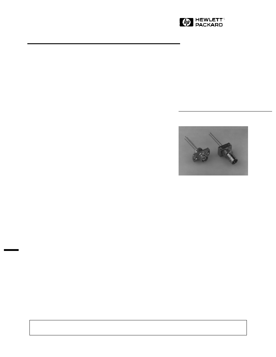
Connectorized PIN Photodiodes
Technical Data
PDT0X1X
Description
The PDT range of products
includes a variety of connector-
ized PIN photodiodes designed
for wide operating temperature,
low cost applications such as
fiber in the loop. The planar
InGaAs photodiodes are manu-
factured using our MOVPE
growth technology and give low
leakage, high responsivity
performance with excellent
reliability.
The construction of the devices
includes a hermetically sealed
photodiode and is designed to be
compatible with the environ-
mental requirements of the
Bellcore TA-TSY-000983
document.
The product range includes a
variety of pinout, connector type
and flange mounting options,
designed to match the majority of
offerings in the marketplace. If
the specific arrangement or
performance you require is not
listed, please contact Hewlett-
Packard. Highly flexible design
and manufacturing processes
allow both physical and electro-
optic customization to suit your
needs.
ST® is a Registered Trademark of AT&T.
ESD WARNING: NORMAL HANDLING PRECAUTIONS SHOULD BE TAKEN TO AVOID STATIC
DISCHARGE.
5965-5857E (11/96)

505
Performance Specification
Test Conditions:
Unless Otherwise Stated
PDT031X
PDT041X
Parameter
Symbol
Vr = 5 V, Tc = 25
°
C
Min.
Max.
Min.
Max.
Units
Dark Current
Id
1
1
nA
Tc = 85
°
C
50
50
nA
Reverse Breakdown
Vbr
Ir = 10
µ
A
35
35
V
Voltage
Capacitance
C
1 MHz
1.1
1.7
pF
Responsivity
R
= 1300 nm
0.7
0.7
A/ W
Operating
80% points
1200
1650
1200
1650
nm
Wavelength
Rise/Fall Times
r/
f
10% to 90%
0.25
0.5
nS
PDT Connectorized PIN Photodiode Specifications
Absolute Maximum Ratings
Absolute maximum limits mean that no catastrophic damage will occur if the product is subjected to these
ratings for short periods, provided each limiting parameter is in isolation and all other parameters have
values within the performance specification. It should not be assumed that limiting values of more than one
parameter can be applied to the product at the same time.
Parameter
Symbol
Minimum
Maximum
Units
Reverse Voltage
Vr
20
V
Reverse Current
Ir
12
mA
Forward Voltage
Vf
1
V
Forward Current
If
5
mA
Power Dissipation
50
mW
Operating Temperature
Tc
-40
85
°
C
Storage Temperature
Ts
-40
85
°
C
Soldering10 seconds
260
°
C
506
B
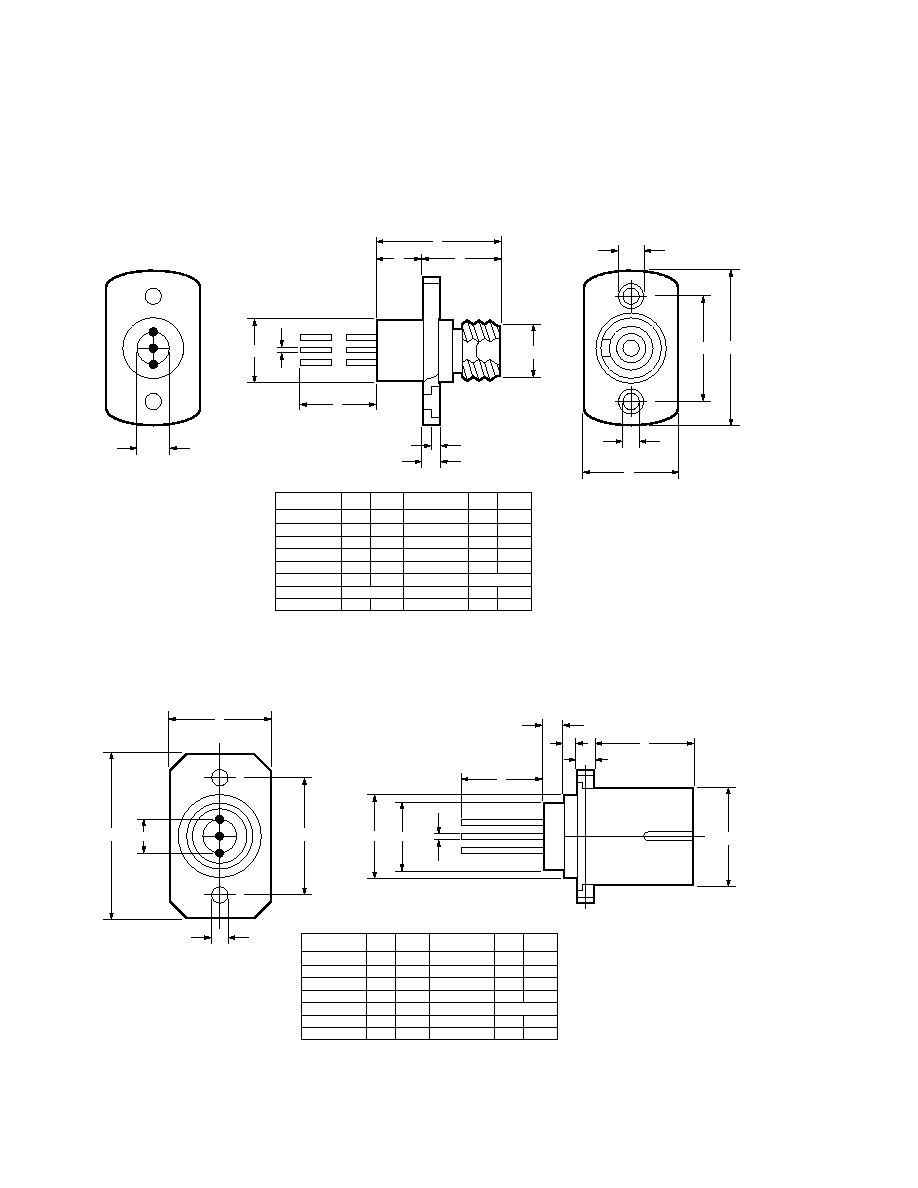
DIMENSION MIN. MAX.
A
B
C
D
E
F
G
9.5
23.0
13.5
12.5
3.1
2.4
3.9
DIMENSION MIN. MAX.
H
I
J
K
L
M
N
12.0
0.41
6.9
2.54 NOM.
2.2
17.5
0.47
7.0
8.6
2.4
18.5
M
G
A
N
L
C
F
E
D
H
K
J
I
ALL DIMENSIONS IN mm.
C
A
DIMENSION MIN. MAX.
A
B
C
D
E
F
G
H
12.0
0.41
M8 X 0.75
13.35
19.5
9.5
15
9.1
0.47
13.55
DIMENSION MIN. MAX.
J
L
M
N
P
Q
R
2.08
2.54 NOM.
2.32
1.65
2.2
6.8
8.2
4.2
Q
J
R
B
H
E
N
P
G
D
F
M
L
SLOT
ALL DIMENSIONS IN mm.
PDT Mechanical Outline Options
PDT0X1X-FC-A
PDT0X1X-SC-A Plastic Housing
507
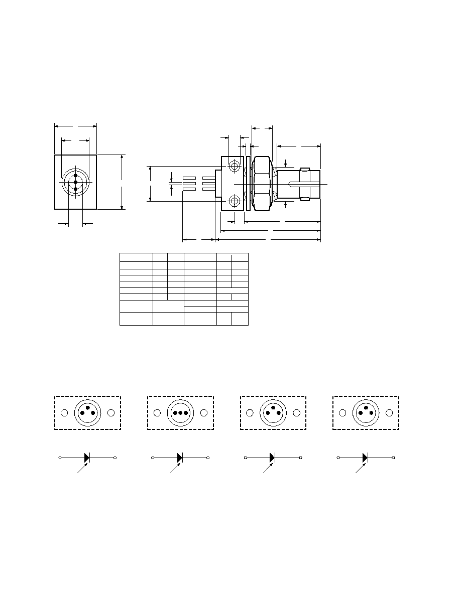
DIMENSION MIN. MAX.
A
B
C
D
E
F
G
H
1.8
9.43
3/8-32
UNEF-2A
2-56
UNC-2B
21.0
2.2
9.8
12.9
9.7
9.63
DIMENSION MIN. MAX.
J
K
L
M
N
P
Q
R
12.0
0.41
2.54 NOM.
14.9
2.54 NOM.
0.50 NOM.
0.47
7.0
22.5
15.3
N
D
E
L
SLOT
K
F
H
R
Q
C
G
M
J
A
P
B
ALL DIMENSIONS IN mm.
PDT Electrical Pinouts
PDT Mechanical Outline Options
PDT1X4X-ST-F
1
3
2
PIN 1: CATHODE +VE
PIN 2: ANODE -VE
PIN 3: TO CASE
2
1
SLOT
PDT0X11
1
3
2
PIN 1: ANODE -VE
PIN 2: CATHODE +VE
PIN 3: TO CASE
1
2
SLOT
PDT0X12
1
3
2
PIN 1: CATHODE +VE
PIN 2: TO CASE
PIN 3: ANODE -VE
3
1
SLOT
PDT0X16
1
3
2
PIN 1: ANODE -VE
PIN 2: CATHODE +VE
PIN 3: TO CASE
1
2
SLOT
PDT0X17

508
Ordering Information
PDT0X1X-XX-X
Flange Type:
A = 2 hole panel mount
F = 2 hole PCB mount, threaded
Connector Type:
FP
ST
®
SC
Pin Out:
Options shown on page 4
Photodiode Diameter:
3 = 50
µ
m
4 = 90
µ
m
Preferred Options:
PDT0311-FC-A
PDT0312-FC-A
PDT0411-FC-A
PDT0411-ST-F
PDT0412-FC-A
PDT0412-ST-F
PDT0417-FC-A
Additional copies are available to meet your specific needs. Please contact your local representative for details.
Handling Precautions
1. The PDT0X1X can be damaged
by current surges of
overvoltage. Power supply
transient precautions should
be taken.
2. Normal handling precautions
for electrostatic sensitive
devices should be taken.
ST® is a Registered Trademark of AT&T.
Document Outline
- Features
- Applications
- Description
- PDT Connectorized PIN Photodiode Specifications
- Absolute Maximum Ratings
- Performance Specification
- PDT Mechanical Outline Options
- PDT0X1X-FC-A
- PDT0X1X-SC-A Plastic Housing
- PDT Mechanical Outline Options
- PDT1X4X-ST-F
- PDT Electrical Pinouts
- Ordering Information
- Handling Precautions