
A31W33128 Series
Preliminary
LCD Controller-Driver
PRELIMINARY (December, 2000, Version 0.1)
AMIC Technology, Inc.
Document Title
LCD Controller-Driver
Revision History
Rev. No. History
Issue Date
Remark
0.0
Initial issue
March 13, 2000
Preliminary
0.1
Error correction:
December 7, 2000
Pad assignment & Boot capacitor connection:
C1+
C1-
C1-
C1+
C2+
C2-
C2-
C2+

A31W33128 Series
Preliminary
LCD Controller-Driver
PRELIMINARY (December, 2000, Version 0.1)
1
AMIC Technology, Inc
Features
n
Power supply range : 2.4V to 5.5V
2.7V to 11.0V (LCD drive)
n
Internal LCD drivers :
128 segment signal drivers
17 /33 commons signal drivers
n
Power save current (<1uA)
n
On chip 128 x 65 Display Data RAM
n
8 BIT 80/68-Series Parallel interface ,Serial interface
n
Build-in RC oscillator or external clock input (18KHz)
n
1:4 / 1:5 / 1:6.7(default) Bias Ratio
n
1:2 to 1:4 Bias Ratio (external)
n
16 level internal contrast control
n
Build-in temperature compensation circuit
n
On chip internal DC/DC converter / External Power supply
n
Dual/ Triple booster
n
2 internal Icon common Output systems
n
TCP package, Gold bumps
The A31W33128 is a CMOS LCD driver, which has 128 segment, and 17 or 33 common graphic display. It has 80/68-series
8 bit parallel and serial interface capability for operating with general CPU. The internal 65 x 128 display data RAM makes
the display of both graphics and characters possible. Besides the general LCD driver features, it has on chip LCD bias
divider circuit such that minimize external component required in system application.

A31W33128 Series
PRELIMINARY (December, 2000, Version 0.1)
2
AMIC Technology, Inc
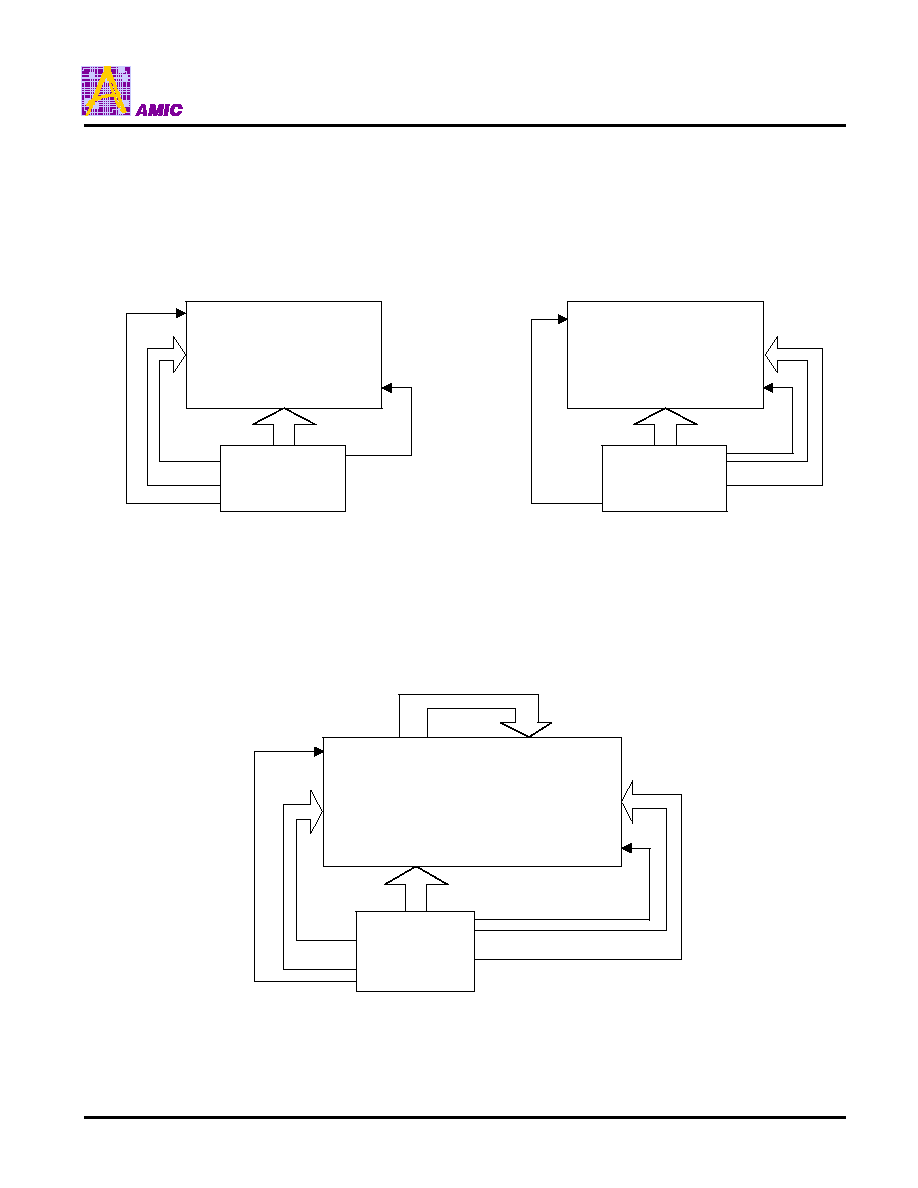
Block Diagram
1. Block Overview
Page
Address
Register
Start
Line
Register
& Counter
Oscillating
Circuit
LCD
Timing
Circuit
Power on
Reset
Display RAM
8320 bits
Page
Address
Decode
Start
Line
Address
Decoder
Data Latch
Column Address
Decoder
Line
Control
Start
Line
Register
LCD Driver
Data
Input/
Output
Column Address
Register & Counter
Display Data
Control
MPU interface
For 68-Series & 80-Series
C1-
Command
Decoder
A0
P/S C68/80 CS
R/W
E
LCD
Power
Supply
Circuit
Status
Register
C1+
C2-
C2+
V
OUT
V
CNT
FNC1
FNC2
V
1
to V
5
VDD
D0 to D7
VSS
COMICN1,2
COM1 to 32
SEG1 to 128
OSC1
OSC2

A31W33128 Series
PRELIMINARY (December, 2000, Version 0.1)
3
AMIC Technology, Inc
Block Diagram
2. LCD Power Supply Circuit Block Diagram
Triple Booster &
Double Booster
Reference
Voltage
Voltage Regular
Reference
Regular
Adjustment
Circuit
Bias
Resister
Voltage
Follower
Command
Register
V4
V3
V2
V1
V5
V
OUT
V
CNT
C1-
C1+
C2-
C2+
CLK
FCN1
FCN2
A31W33128 Series
PRELIMINARY (December, 2000, Version 0.1)
4
AMIC Technology, Inc
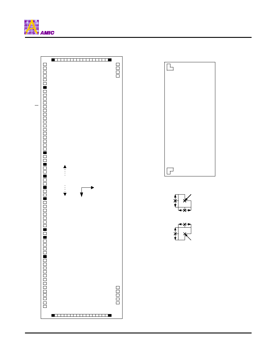
Pad Assignment
TEST0
TEST1
TEST2
TEST3
TEST4
TEST5
NC
VDD
VDD
VDD
CS
A0
R/W
E
P/S
C68/80
OSCO
OSCI
VSS
VSS
VSS
VSS
NC
D0
D1
NC
D2
D3
NC
D4
D5
NC
D6
D7
NC
FNC2
FNC1
VSS
VSS
VSS
TEST6
NC
V
OUT
C2+
C2-
NC
C1+
C1-
NC
V
CNT
TEST7
TEST8
VDD
TEST9
V5
V4
V3
V2
V1
ICN1
1
2
3
4
5
6
7
8
9
10
11
12
13
14
15
16
ICN2
17
19
21
23
25
27 29 31
18
20
22
26
24
28 30
32
.
.
.
.
.
.
.
.
.
.
.
.
.
.
.
.
.
.
.
.
.
.
.
.
.
.
.
.
.
.
.
.
.
.
.
.
.
.
.
.
.
.
.
.
.
.
.
.
.
.
.
.
.
.
.
.
.
.
.
.
.
.
.
.
.
.
.
.
.
.
.
.
.
.
.
.
.
.
.
.
.
.
.
.
.
.
.
.
.
.
.
.
.
.
.
.
.
.
.
.
.
.
.
.
.
.
.
.
COM Output
SEG128
SEG127
SEG126
SEG125
SEG5
SEG4
SEG3
SEG2
SEG1
COM Output
(0,0)
Control
Pins
. Pad pitch
Segment driver 65um
Comon driver 65um
Control pad 120um
. Gold bump size
Drive 43x85um
Input pin 72x85um
. Gold bump height 18um (Typ.)
VDD
VSS
VDD
VDD
VDD
Chip Identification Marks
(The identification marks are larger than the actual scaling)
50 50
50 50
50
50
50
50
(4096.5, 740)
(-4097.5, 740)
(The identification marks are made of AI patterns)
Unit : um

A31W33128 Series
PRELIMINARY (December, 2000, Version 0.1)
5
AMIC Technology, Inc
Pad Coordinates
Unit:
�
m (The origin is the center of the chip)
No.
Pin Name
X
Y
No.
Pin Name
X
Y
1
TEST0
-3877.5
-897.5
64
TEST9
3877.7
-897.5
2
TEST1
-3807.5
-897.5
65
NC
4103.5
-717.5
3
TEST2
-3737.5
-897.5
66
COM17
4103.5
-647.5
4
TEST3
-3667.5
-897.5
67
COM18
4103.5
-577.5
5
TEST4
-3597.5
-897.5
68
COM19
4103.5
-507.5
6
TEST5
-3527.5
-897.5
69
COM20
4103.5
-437.5
7
NC
-3457.5
-897.5
70
COM21
4103.5
-367.5
8
VDD
-3371.5
-897.5
71
COM22
4103.5
-297.5
9
VDD
-3251.5
-897.5
72
COM23
4103.5
-227.5
10
VDD
-3131.5
-897.5
73
COM24
4103.5
-157.5
11
VDD
-3011.5
-897.5
74
COM25
4103.5
-87.5
12
CS
-2891.4
-897.5
75
COM26
4103.5
-17.5
13
A0
-2763.6
-897.5
76
COM27
4103.5
52.5
14
R/W
-2635.8
-897.5
77
COM28
4103.5
122.5
15
E
-2508
-897.5
78
COM29
4103.5
192.5
16
P/S
-2380.2
-897.5
79
COM30
4103.5
262.5
17
C68/80
-2252.4
-897.5
80
COM31
4103.5
332.5
18
OSCO
-2124.6
-897.5
81
COM32
4103.5
402.5
19
OSCI
-1996.8
-897.5
82
COMICN2
4103.5
472.5
20
VSS
-1876.8
-897.5
83
NC
4103.5
548.5
21
VSS
-1756.8
-897.5
84
SEG1
4127.5
897.5
22
VSS
-1636.8
-897.5
85
SEG2
4062.5
897.5
23
VSS
-1516.8
-897.5
86
SEG3
3997.5
897.5
24
NC
-1430.8
-897.5
87
SEG4
3932.5
897.5
25
D0
-1264.2
-897.5
88
SEG5
3867.5
897.5
26
D1
-999.8
-897.5
89
SEG6
3802.5
897.5
27
NC
-835.2
-897.5
90
SEG7
3737.5
897.5
28
D2
-670.6
-897.5
91
SEG8
3672.5
897.5
29
D3
-406.2
-897.5
92
SEG9
3607.5
897.5
30
NC
-241.6
-897.5
93
SEG10
3542.5
897.5
31
D4
-77
-897.5
94
SEG11
3477.5
897.5
32
D5
187.4
-897.5
95
SEG12
3412.5
897.5
33
NC
352
-897.5
96
SEG13
3347.5
897.5
34
D6
516.6
-897.5
97
SEG14
3282.5
897.5
35
D7
781
-897.5
98
SEG15
3217.5
897.5
36
NC
945.6
-897.5
99
SEG16
3152.5
897.5
37
FNC2
1049.2
-897.5
100
SEG17
3087.5
897.5
38
FNC1
1177
-897.5
101
SEG18
3022.5
897.5
39
VSS
1298.7
-897.5
102
SEG19
2957.5
897.5
40
VSS
1418.7
-897.5
103
SEG20
2892.5
897.5
41
VSS
1538.7
-897.5
104
SEG21
2827.5
897.5
42
VSS
1658.7
-897.5
105
SEG22
2762.5
897.5
43
TEST6
1744.7
-897.5
106
SEG23
2697.5
897.5
44
NC
1814.7
-897.5
107
SEG24
2632.5
897.5
45
V
OUT
1900.7
-897.5
108
SEG25
2567.5
897.5
46
NC
1981.7
-897.5
109
SEG26
2502.5
897.5
47
C2+
2062.7
-897.5
110
SEG27
2437.5
897.5
48
C2-
2182.7
-897.5
111
SEG28
2372.5
897.5
49
C1+
2302.7
-897.5
112
SEG29
2307.5
897.5
50
C1-
2422.7
-897.5
113
SEG30
2242.5
897.5
51
NC
2503.7
-897.5
114
SEG31
2177.5
897.5
52
V
CNT
2589.7
-897.5
115
SEG32
2112.5
897.5
53
TEST7
2675.7
-897.5
116
SEG33
2047.5
897.5
54
TEST8
2745.7
-897.5
117
SEG34
1982.5
897.5
55
VDD
2831.7
-897.5
118
SEG35
1917.5
897.5
56
VDD
2951.7
-897.5
119
SEG36
1852.5
897.5
57
VDD
3071.7
-897.5
120
SEG37
1787.5
897.5
58
VDD
3191.7
-897.5
121
SEG38
1722.5
897.5
59
V1
3311.7
-897.5
122
SEG39
1657.5
897.5
60
V2
3431.7
-897.5
123
SEG40
1592.5
897.5
61
V3
3551.7
-897.5
124
SEG41
1527.5
897.5
62
V4
3671.7
-897.5
125
SEG42
1462.5
897.5
63
V5
3791.7
-897.5
126
SEG43
1397.5
897.5

A31W33128 Series
PRELIMINARY (December, 2000, Version 0.1)
6
AMIC Technology, Inc
Pad Coordinates (continued)
Unit:
�
m (The origin is the center of the chip)
No.
Pin Name
X
Y
No.
Pin Name
X
Y
127
SEG44
1332.5
897.5
190
SEG107
-2762.5
897.5
128
SEG45
1267.5
897.5
191
SEG108
-2827.5
897.5
129
SEG46
1202.5
897.5
192
SEG109
-2892.5
897.5
130
SEG47
1137.5
897.5
193
SEG110
-2957.5
897.5
131
SEG48
1072.5
897.5
194
SEG111
-3022.5
897.5
132
SEG49
1007.5
897.5
195
SEG112
-3087.5
897.5
133
SEG50
942.5
897.5
196
SEG113
-3152.5
897.5
134
SEG51
877.5
897.5
197
SEG114
-3217.5
897.5
135
SEG52
812.5
897.5
198
SEG115
-3282.5
897.5
136
SEG53
747.5
897.5
199
SEG116
-3347.5
897.5
137
SEG54
682.5
897.5
200
SEG117
-3412.5
897.5
138
SEG55
617.5
897.5
201
SEG118
-3477.5
897.5
139
SEG56
552.5
897.5
202
SEG119
-3542.5
897.5
140
SEG57
487.5
897.5
203
SEG120
-3607.5
897.5
141
SEG58
422.5
897.5
204
SEG121
-3672.5
897.5
142
SEG59
357.5
897.5
205
SEG122
-3737.5
897.5
143
SEG60
292.5
897.5
206
SEG123
-3802.5
897.5
144
SEG61
227.5
897.5
207
SEG124
-3867.5
897.5
145
SEG62
162.5
897.5
208
SEG125
-3932.5
897.5
146
SEG63
97.5
897.5
209
SEG126
-3997.5
897.5
147
SEG64
32.5
897.5
210
SEG127
-4062.5
897.5
148
SEG65
-32.5
897.5
211
SEG128
-4127.5
897.5
149
SEG66
-97.5
897.5
212
NC
-4103.5
542.5
150
SEG67
-162.5
897.5
213
COM16
-4103.5
472.5
151
SEG68
-227.5
897.5
214
COM15
-4103.5
402.5
152
SEG69
-292.5
897.5
215
COM14
-4103.5
332.5
153
SEG70
-357.5
897.5
216
COM13
-4103.5
262.5
154
SEG71
-422.5
897.5
217
COM12
-4103.5
192.5
155
SEG72
-487.5
897.5
218
COM11
-4103.5
122.5
156
SEG73
-552.5
897.5
219
COM10
-4103.5
52.5
157
SEG74
-617.5
897.5
220
COM9
-4103.5
-17.5
158
SEG75
-682.5
897.5
221
COM8
-4103.5
-87.5
159
SEG76
-747.5
897.5
222
COM7
-4103.5
-157.5
160
SEG77
-812.5
897.5
223
COM6
-4103.5
-227.5
161
SEG78
-877.5
897.5
224
COM5
-4103.5
-297.5
162
SEG79
-942.5
897.5
225
COM4
-4103.5
-367.5
163
SEG80
-1007.5
897.5
226
COM3
-4103.5
-437.5
164
SEG81
-1072.5
897.5
227
COM2
-4103.5
-507.5
165
SEG82
-1137.5
897.5
228
COM1
-4103.5
-577.5
166
SEG83
-1202.5
897.5
229
COMICN1
-4103.5
-647.5
167
SEG84
-1267.5
897.5
230
NC
-4103.5
-717.5
168
SEG85
-1332.5
897.5
169
SEG86
-1397.5
897.5
170
SEG87
-1462.5
897.5
171
SEG88
-1527.5
897.5
172
SEG89
-1592.5
897.5
173
SEG90
-1657.5
897.5
174
SEG91
-1722.5
897.5
175
SEG92
-1787.5
897.5
176
SEG93
-1852.5
897.5
177
SEG94
-1917.5
897.5
178
SEG95
-1982.5
897.5
179
SEG96
-2047.5
897.5
180
SEG97
-2112.5
897.5
181
SEG98
-2177.5
897.5
182
SEG99
-2242.5
897.5
183
SEG100
-2307.5
897.5
184
SEG101
-2372.5
897.5
185
SEG102
-2437.5
897.5
186
SEG103
-2502.5
897.5
187
SEG104
-2567.5
897.5
188
SEG105
-2632.5
897.5
189
SEG106
-2697.5
897.5

A31W33128 Series
PRELIMINARY (December, 2000, Version 0.1)
7
AMIC Technology, Inc
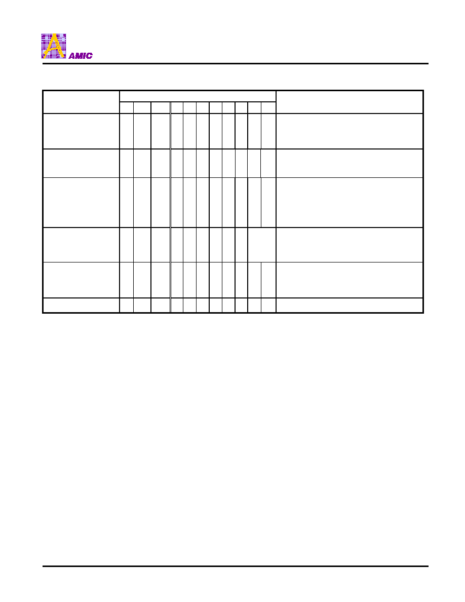
Input/Output Pin Function
Pin No.
Symbol
Type
Description
20-23,
39-42
VSS
Supply
GROUND
8-11,
55-58
VDD
Supply
Power supply pin
18
OSCO
Output
Oscillator output
19
OSCI
Input
Oscillator input
12
CS
Input
Chip select input, low active
13
A0
Input
A0=Low: Command input.
A0=High: Display data input and outputs
68-Series R/W=High: Read, R/W=Low : Write
14
R/W
Input
80-Series : Write enable, Active Low
68-Series : Enable clock signal input, Active High
15
E
Input
80-Series : Read enable, Active Low
16
P/S
Input
Parallel/serial interface select input
High : 8-bit parallel interface
Low : Serial interface
17
C68/80
Input
Microprocessor interface select input
High : 68-Series interface is selected
Low : 80-Series interface is selected
25-26,
28-29,
31-32,
34-35
D0-7
Input/
Output
8bit bi-directional data bus to be connected to microprocessor's data bus
P/S=High : 8-bit configuration data bus connection
P/S=Low : Serial interface connection
D0 Serial data input
D1 Serial clock input
D2 Serial data output
84-211
SEG1-
SEG128
Output
Provide the LCD segment driving signal
66-81
213-228
COM1-
COM32
Output
Provide the LCD common driving signal
229
82
COMICN1
COMCN2
Output
Provide the Icon common driving signal
COMICN1 and COMICN2 output the same phase waveform.
37
FNC2
Input
LCD power control input pin
38
FNC1
Input
LCD power control input pin
42
V
OUT
Output
Boosting voltage output
47
C2+
Input
2nd-step boosting capacitor negative connection
48
C2-
Input
2nd-step boosting capacitor positive connection
49
C1+
Input
1 st-step boosting capacitor negative connection
50
C1-
Input
1 st-step boosting capacitor positive connection
52
V
CNT
Input
LCD power supply voltage control

A31W33128 Series
PRELIMINARY (December, 2000, Version 0.1)
8
AMIC Technology, Inc
Input/Output Pin Function (continued)
Pin No.
Symbol
Type
Description
59
V1
Input
60
V2
Input
61
V3
Input
62
V4
Input
63
V5
Input
LCD driver bias voltage. They can be supplied externally or generated by the internal
bias divider.
1: 4 bias 1: 5 bias 1: 6.75 bias
V1 1/4 x V5 1/5 x V5 1/6.75 x V5
V2 2/4 x V5 2/5 x V5 2/6.75 x V5
V3 2/4 x V5 3/5 x V5 4.75/6.75 x V5
V4 3/4 x V5 4/5 x V5 5.75/6.75 x V5
� Inputs LCD drive bias voltage when using an external LCD power supply circuit.
V5
V4, V3, V2, V1 > VSS
1-7,
24, 27,
30, 33,
36,
43-44,
46, 51,
53-54,
64-65,
83,
212, 230
NC
Open
No Connection
1
TEST0
2
TEST1
3
TEST2
4
TEST3
5
TEST4
6
TEST5
43
TEST6
53
TEST7
54
TEST8
64
TEST9
Open
Cannot be wired to the outside

A31W33128 Series
PRELIMINARY (December, 2000, Version 0.1)
9
AMIC Technology, Inc
Commands Table
Bit pattern
Command
A0 E R/W D7 D6 D5 D4 D3 D2 D1 D0
Comment
Set Display ON/OFF
0
1
0
1 0 1 0 1 1 1 0
1
D0:0 Display OFF: Display goes out, regardless
of the content of the display
data RAM
D0:1 Display ON: Normal Display
Set Display Start Line
0
1
0
0 1
Display start line address
Sets the line address of the display data
RAM output to COM1
Page Address Set
0
1
0
1 0 1 1 Page Address Sets the page address of the display data
RAM. Page 8 is assigned to the icon display
Upper 3 bits of Column
Address Set
0
1
0
0 0 0 1 0
Upper 3 bits of
Column
Address
Sets upper 3 bits of the display data RAM
Column Address
Lower 4 bits of the
Column Address Set
0
1
0
0 0 0 0
Lower 4 bits of the
Column Address
Lower 4 bits of display data RAM column
Address
Status Read
0
0
1
Status
Status Read
Display Data
Write
1
1
0
Write Data in
Display Data RAM
Writes data of D0 to D7 in the display data RAM
Display Data
Read
1
0
1
Read Data from
Display Data RAM
Reads data from D0 to D7 from the display data
RAM
ADC Select
0
1
0
1 0 1 0 0 0 0 0
1
Reverses upper or lower display data RAM
column address
D0:0 Normal: Column addresses 00 to 7FH
correspond to segment outputs 1
to 128
D0:1 Reverse: Column addresses 00 to 7FH
correspond to segment outputs
128 to 1
Display
Normal/Reverse
0
1
0
1 0 1 0 0 1 1 0
1
D0:0 Normal : "1" makes the display be lit
D0:1 Reverse : "0" makes the display be lit
The icon display is not reversed
Display All-Lit ON/OFF 0
1
0
1 0 1 0 0 1 0 0
1
D0:0 Normal Display
D0:1 Display All-Lit
Duty Selection/
Alternate Common
Output
0
1
0
1 0 1 0 1 0
*
0
1
0
1
1
D0:0 1/17 Duty
D0:1 1/33 Duty
D1:0 Common output order: In a numerical order
D1:1 Common output order: Alternate output to
right and left of the chip.
Read Modify Write
0
1
0
1 1 1 0 0 0 0 0 Increments display data RAM column
address only during writing
End
0
1
0
1 1 1 0 1 1 1 0 Read Modify Write Release.
Reset
0
1
0
1 1 1 0 0 0 1 0 It does not affect the contents of the display data
RAM.
After resetting, display starts according to the
reset value:
1.Resets the display start line register to the
1st line.
2.Resets the column address counter to
address 0.
3.Resets the page address counter to page 0.
4.Clears the serial interface counter.
5.Turns OFF the Read Modify Write.
A31W33128 Series
PRELIMINARY (December, 2000, Version 0.1)
10
AMIC Technology, Inc
Commands Table (continued)
Bit pattern
Command
A0 E R/W D7 D6 D5 D4 D3 D2 D1 D0
Comment
Bias Selection
0
1
0
0 0 1 0 1 0 D1 D0 D1,D0:0, 0 1/6.75 Bias Selection
D1,D0:0, 1 1/5 Bias Selection
D1,D0:1, 0 1/4 Bias Selection
D1,D0:1, 1 Don't care
LCD Voltage Command
Fine Adjustment Data
0
1
0
1 0 0 0
0
.
1
0
.
1
0
.
1
0
.
1
Minimum value (default)
Maximum value
LCD Power Supply
Circuit ON/OFF
0
1
0
0 0 1 0 0 1 0
0
1
D0: 0 LCD power supply circuit OFF
D0: 1 LCD power supply circuit ON
The LCD power supply circuit connected to
pinsFNC1, FNC2 starts its operation earlier
than the LCD POWER Supply circuit ON/OFF
command.
Icon Only Display
0
1
0
1 1 0 0 0 D2
Boosting
Control
Data
D2: 0 Normal Display
D2: 1 Icon Only Display
Boosting control data: Selects boosting
Frequency
Reference Voltage
Temperature
Coefficient
Selection
0
1
0
1 1 1 0 0 1 *
0
1
D0:0 -0.13%/
�
C
D0:1 +0.01%/
�
C
Power save
Display OFF, Display all-lit ON

A31W33128 Series
PRELIMINARY (December, 2000, Version 0.1)
11
AMIC Technology, Inc
Operation of LCD Display Driver
1. Powering ON setting sequence
Recommended Command Setting Sequence:
(1) Set Display OFF : In order to prevent unnecessary characters from being displayed during powering ON of
the power .
The state is changed to the " Power save mode" after turning on the Display All-Lit ON with
the display OFF.
(2) Set Display All-Lit OFF: Normal display operation and the oscillation start.
(3) Set LCD Power Supply Circuit ON
(4) Set Bias Select
(5) Set Reference Voltage Temperature Compensation Coefficient
(6) End Command Input
(7) Set Duty Select/Alternate Common Output
(8) Set Display Normal/Reverse :
D0 : 0 Normal Display data "1" makes the display be lit.
D0 : 1 Reverse Display data "0" makes the display be lit.
(9) Set Display Start Line address: Changing the display start line allows for page change on the display screen
as well as vertical smooth scroll.
(10) Common Output Sequence
(11) Icon Only Display
(12) Display Data Write: After writing the display data, the column address is automatically incremented. To write
the display data in succession after setting the 1st column address to be written by the COLUMN ADDRESS
SETTING command, the column address is not needed to be set each time. The icon display data is valid for
only D0.
Write "L" or data to be displayed in all display data RAM before turning the display ON.
(13) Display ON
2. Set Powering OFF, Power Save Mode
Set Powering OFF sequence:
(1) Set Display OFF
(2) Set LCD Power Supply Circuit OFF
Power Save Mode:
When in Power save mode, the command sleeps the system :
�
Internal oscillating circuit and LCD power supply circuit are stopped.
�
The Segment and Common outputs are fixed at VSS level.
�
The LCD display goes out.
�
The contents of the display data RAM, the command and the address before the power save mode do not
change.
Combination of Commands
State
Display ON
Display ON
Display OFF
Display OFF
Display All-Lit OFF
Display All-Lit ON
Display All-Lit OFF
Display All-Lit ON
Normal display operation
All-lit display
AII-OFF
Power save
A31W33128 Series
PRELIMINARY (December, 2000, Version 0.1)
12
AMIC Technology, Inc
3. MPU Interface Select
The parallel 68-series, 80-series interface or serial interface can be selected by P/S, C68/80 pin setup:
P/S Pin
C68/80 Pin
MPU Interface
L
80-series Interface selected
H
H
68-series Interface selected
L
don't care
Serial Interface selected
3.1 MPU Parallel 68-Series and 80-Series Interface
The parallel interface consists of 8 bi-directional data pins (D0-D7), R/W(
WR
), A0, E(
RD
),
CS
In order to match the
operating frequency of display RAM with that of the microprocessor, some pipeline processing is internally performed
which requires the insertion of a dummy read before the first actual display data read.
A31W33128 Pin Name
A0
E
R/W
CS
D0 - D7
68-Series MPU Signal
A0
E
R/W
CS
D0 - D7
80-Series MPU Signal
A0
RD
WR
CS
D0 - D7
3.2 MPU Serial Interface
The serial interface consists of serial clock input SCLK, serial data input SDI and output SDO, chip select
CS
, P/S,
R/W, A0. When the E pin to be open and the serial interface is selected by setting P/S to "L", the instruction code is
the same as for the parallel interface .By setting
CS
to "L". the serial interface circuit enters an operating state. And by
setting
CS
to "H', it will reset the serial interface circuit and initialized the counter.
Data is input in the order of D0, D1, D2,....D7. The displayed data and commands are written at the rising edge of the
SCLK. But the displayed data and status are read at the falling edge of the SCLK. Data read needs a dummy read.
When in reset condition, the SDO pin will be driven to "H", and the status reading will be invalidated.
D0 (SDI)
: Serial Data Input
D1 (SCLK) : Serial Clock Input
D2 (SDO) : Serial Data Output
D3 to D7
: Open
E
: Open
C68/80
: Open
A0
R/W
Operation
L
L
Command input
H
H
Display data read
L
H
Status read
H
L
Display data write
4. Command Execution
When the input at D0-D7 is interpreted as a command and it will be decoded and written to the corresponding command
register. The user can input the commands continuously without confirming the busy flag of status command register
because the command is completely executed within the cycle time (tcyc) according to the timing characteristics of the
command input. But that re-inputting the command within the executed cycle time is inhibited.

A31W33128 Series
PRELIMINARY (December, 2000, Version 0.1)
13
AMIC Technology, Inc
5. Data Bus Select
When
CS
is held at "H" level, the D0-D7 is in high impedance state.
68/80-Series
shared
68-Series
80-Series
A0
R/W
E
R/W
Description
1
1
0
1
Reads from Display Data RAM
1
0
1
0
Writes to Display Data RAM
0
1
0
1
Reads Status
0
0
1
0
Command Write to internal register
6. Display Data RAM
The Display Data RAM is made of dual port RAM. The size of the RAM is 64 x 128 + 128 = 8320 bits.
Write "L" or data to be displayed in all display data RAM before turning the display ON.
7. Accessing the Display Data RAM From MPU
In order to match the operating frequency of Display Data RAM with that of the MPU, a dummy read is required before the
first actual display data read. When the MPU reads the Display Data RAM, the first dummy read cycle stores the first read
data in the bus holder, and then at the next read cycle the MPU read the first read data from the bus holder.
It does not need a dummy cycle when MPU writes data to the Display Data RAM. When the MPU write data to Display Data
RAM, once the data is stored in the bus holder, then it is written to Display Data RAM before the next data write cycle.
8. Set Column Address (higher, lower nibble)
This command specifies the column address (higher and lower nibble) of the Display Data RAM. The column address will be
incremented by each data access after it is pre-set by the MPU.
9. Set Page Address(0-8)
This command positions the page address to 1 of 9 possible positions in Display Data RAM. Page 0-7 are the graphic
display area, and the page 8 are the Icon display area.
10. Set display start line (0-63)
The command is used to change the display page or smooth scroll.
With the display start line value equals to 0, D0 of page 0 is mapped to COM1. The display start line values of 0 to 63 are
assigned to page 0 to 7.

A31W33128 Series
PRELIMINARY (December, 2000, Version 0.1)
14
AMIC Technology, Inc
11. Status Read
This command shows the status of A31W33128
BUSY
: D7
=0 : The A31W33128 is not busy
1 : The A31W33128 is in internal operation or reset state.
ADC
: D6
=0 : ADC Reverse : Column addresses 00 to 7FH correspond to segment outputs 128 to 1.
1 : ADC Normal : Column addresses 00 to 7FH correspond to segment outputs 1 to 128.
ON/OFF : D5
=0 : Display ON
1 : Display OFF
RESET : D4
=0 : In normal operation state
1 : Internal reset operation state
PSAVE : D3
=0 : In normal operation state
1 : In Power Save state
ICON
: D2
=0 : In normal operation state
1 : In Icon only display state
DREV
: D1
=0 : Display Normal
1 : Display Reverse
ALON
: D0
=0 : Normal display
1 : Display All-Lit ON
When a serial interface is selected, the status read from the SDO pin is always high level during reset operation.
12. 1/33 ,1/17 Duty Select, Alternate Common Output
Common Output sequence at duty 1/33
Output sequence
Common driving signal output in numerical
Common driving signal Alternate Output
1
COM1
COM1
2
COM2
COM17
3
COM3
COM2
.
.
.
.
.
.
16
COM16
COM9
17
COM17
COM25
.
.
.
.
.
.
31
COM31
COM16
32
COM32
COM32
33
COMICN1,2
COMICN1,2
Common Output sequence at duty 1/17
Output sequence Common driving signal output in numerical
1
COM1,17
2
COM2,18
3
COM3,19
.
.
.
.
15
COM15,31
16
COM16,32
17
COMICN1,2
The common output at duty 1/17 only has in numerical sequence.

A31W33128 Series
PRELIMINARY (December, 2000, Version 0.1)
15
AMIC Technology, Inc
13. Read Modify Write , END
Read Modify Write
This command puts the chip in read modify write mode. In this mode the column address is saved before entering the
mode, and is incremented by display data write but not by display data read. During the Read Modify Write mode, all
commands are usable except the Column address set command.
End
This command relieves the A31W33128 from read modify write mode. The column address that is saved before entering
read modify write mode will be restored.
14. Boosting frequency select
Select the boosting frequency:
D1
D0
Boosting Freq.
0
0
Fosc/2
0
1
Fosc/4
1
0
Fosc/8
1
1
Fosc/16
15. RC Oscillator Circuit
The built-in RC oscillator generates the clock for the boosting frequency, and is also used in the display timing. When
using the external clock, the external clock is input to OSCI, and OSCO is left floating.
Used built-in RC oscillator , Rf = 1 M
1/17 duty
Frame freq. 66.17 Hz at fosc = 18 KHz
1/33 duty
Frame freq.68.18 Hz at fosc = 18 KHz
16. Reference Voltage Temperature Compensation Coefficient Select
This command is to set one out of 2 different temperature coefficients in order to match various liquid crystal temperature
grades.
V
REF
=
1
2
1
REF
2
REF
T
T
)I
(T
IV
)I
(T
IV
-
-
T
2
> T
1
A31W33128 Series
PRELIMINARY (December, 2000, Version 0.1)
16
AMIC Technology, Inc
V5=
Ra + Rb
Ra
X VREF (V)
Rb
Ra
VREF
VSS
VCNT
V5
+
-
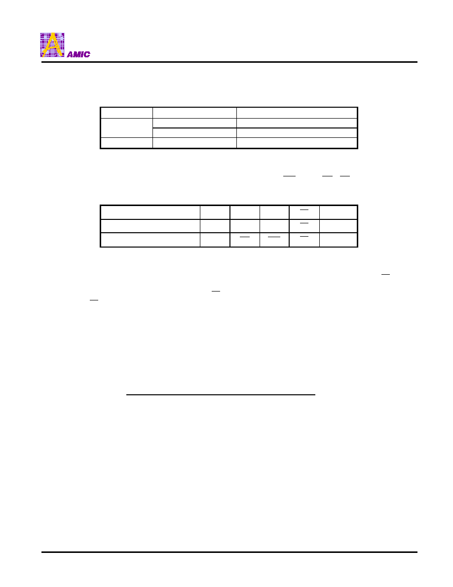
VDD=3V
VSS
Example of Booster Output
Double VOUT = 6V
Triple VOUT = 9V
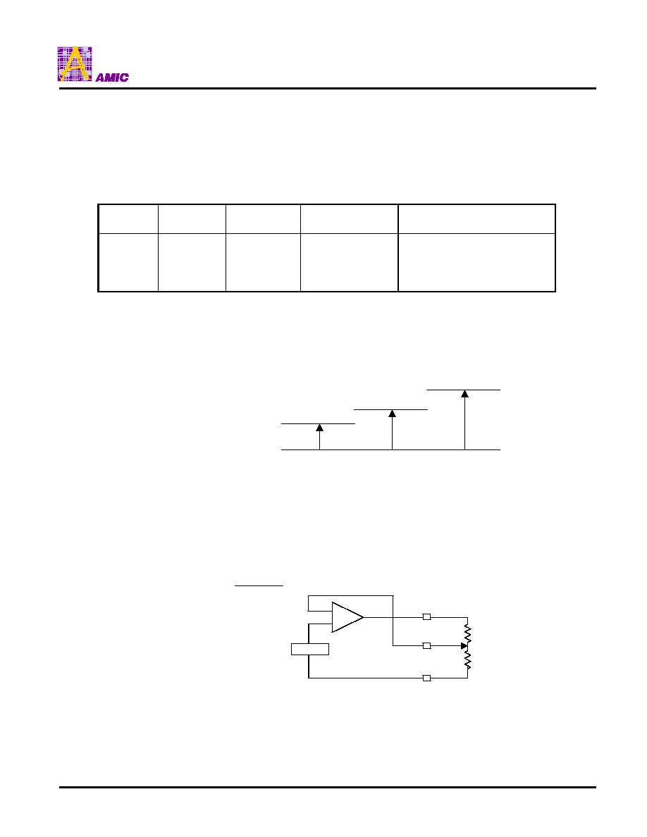
17. LCD Power Supply Circuit
The LCD power supply circuit generates the LCD voltage needed for display output, which is controlled by pins FNC1
,FNC2 and LCD power supply circuit ON/OFF command. It consists of:
1. Doubler/tripler DC-DC voltage converter.
2. Voltage regulator and LCD voltage command fine adjustment circuit.
3. LCD bias resistor and voltage follower
FNC2
FNC1
Doubler/Tripler
Circuit
Voltage Regulator
Circuit
LCD Bias Resistor/
Voltage Follower Circuit
L
H
L
H
L
L
H
H
ON
OFF
OFF
OFF
ON
OFF
ON
OFF
ON
OFF
ON
ON
�
FNC1 and FNC2 must connect to VDD or VSS.
�
Don't connect the external power supply with the built-in LCD power supply circuit ON, it may lead to a breakdown.
17.1 Doubler/Tripler
It is the 2X, 3X DC-DC voltage converter. Please refer to application notes.
17.2 LCD Voltage Adjustment
There are two methods of adjusting the LCD voltage as follows:
17.2.1 Voltage Regulator
Voltage regulator output V5 is adjusted by externally attached Ra and Rb.

A31W33128 Series
PRELIMINARY (December, 2000, Version 0.1)
17
AMIC Technology, Inc
17.2.2 LCD Voltage Command Fine Adjustment control
Software control of 16 voltage levels adjustment of V5 voltage by set 4 bits of the data bus. It can adjust the LCD
contrast.
17.3 LCD Bias voltage
When use built-in LCD bias resistor, Software can control the 1/6.7, 1/5,1/4 bias ratio to match the characteristic of
LCD panel.
17.4 Voltage Follower
The voltage follower buffers the LCD bias voltage created by the built-in bias resistor, and supplies it to the LCD drive
circuit.
A31W33128 Series
PRELIMINARY (December, 2000, Version 0.1)
18
AMIC Technology, Inc
Interface
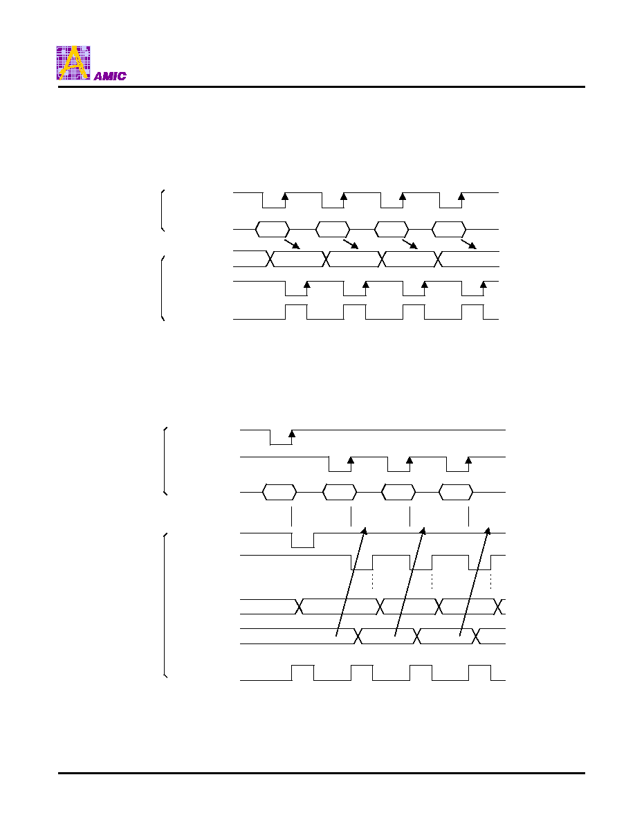
1. Parallel Interface
1.1 Display Data Write ( the 80-Series interface)
1.2 Display Data Read (the 80-Series interface)
n
n+1
n+2
n+3
n+3
n+2
n+1
n
R/W
Data
Bus Holder
R/W
Internal Busy Flag
MP
Internal
Timing
N
X
n
n+1
R/W
Data
Bus Holder
R/W
Internal Busy Flag
MP
Internal
Timing
Address set
address N
Dummy
read
Data read
address N
Data read
address N+1
N
N+1
N+2
n+2
n+1
n
X
E
E
Column address

A31W33128 Series
PRELIMINARY (December, 2000, Version 0.1)
19
AMIC Technology, Inc
D0
CS
R/W
D1
D2
D3
D4
D5
D6
D7
D0
D0
D1
D2
D3
D4
D5
D6
D7
D0
A0
D1
(SCLK)
D0
(SDI)
D2
(SDO)
2
Serial Interface
Serial Interface Display Data Write/Read Timing
A0
R/W
D0 (SDI)
D2 (SDO)
0
0
Command Write
Invalid
0
1
Invalid
Status Read
1
0
Data Write
Invalid
1
1
Invalid
Data Read
(Note)
Note: Data Read needs a dummy read

A31W33128 Series
PRELIMINARY (December, 2000, Version 0.1)
20
AMIC Technology, Inc
Display Data RAM vs Address
Page
Address
Page0
00
H
01
H
02
H
03
H
04
H
05
H
06
H
07
H
0, 0, 0, 0
Line
Address
D0
D1
D2
D3
D4
D5
D6
D7
Page1
08
H
09
H
0A
H
0B
H
0C
H
0D
H
0E
H
0F
H
0, 0, 0, 1
D0
D1
D2
D3
D4
D5
D6
D7
Page2
10
H
11
H
12
H
13
H
14
H
15
H
16
H
17
H
0, 0, 1, 0
D0
D1
D2
D3
D4
D5
D6
D7
Page3
18
H
19
H
1A
H
1B
H
1C
H
1D
H
1E
H
1F
H
0, 0, 1, 1
D0
D1
D2
D3
D4
D5
D6
D7
Page4
20
H
21
H
22
H
23
H
24
H
25
H
26
H
27
H
0, 1, 0, 0
D0
D1
D2
D3
D4
D5
D6
D7
Page5
28
H
29
H
2A
H
2B
H
2C
H
2D
H
2E
H
2F
H
0, 1, 0, 1
D0
D1
D2
D3
D4
D5
D6
D7
Page6
30
H
31
H
32
H
33
H
34
H
35
H
36
H
37
H
0, 1, 1, 0
D0
D1
D2
D3
D4
D5
D6
D7
Page7
38
H
39
H
3A
H
3B
H
3C
H
3D
H
3E
H
3F
H
0, 1, 1, 1
D0
D1
D2
D3
D4
D5
D6
D7
1, 0, 0, 0
D0
Page8
40
H
Column
Address
ADC
D0=
"0"
SEG Pin
ADC
D0=
"1"
00 01 02 03 04 05 06 07..............
7F 7E 7D 7C 7B 7A 79 78
..............
1 2 3 4 5 6 7 8...............
.... .... ......
01 00
......
3F 40
7E 7F
.... .... ......
127128
COM1
COM2
COM3
COM4
COM5
COM6
COM7
COM8
COM9
COM10
COM11
COM12
COM13
COM14
COM15
COM16
COMICN1,2
Display
Start
COM17
COM18
COM19
COM20
COM21
COM22
COM23
COM24
COM25
COM26
COM27
COM28
COM29
COM30
COM31
COM32
COM1, 17
COM2, 18
COM3, 19
COM4, 20
COM5, 21
COM6, 22
COM7, 23
COM8, 24
COM9, 25
COM10, 26
COM11, 27
COM12, 28
COM13, 29
COM14, 30
COM15, 31
COM16, 32
COMICN1,2
An example of common output
executing display start from line
address 30
H
at 1/17 duty.
An example of common
output executing display
start from line address
30
H
at 1/33 duty.

A31W33128 Series
PRELIMINARY (December, 2000, Version 0.1)
21
AMIC Technology, Inc
LCD Drive Output Waveform (Waveform B)
The following is an example of how the common and segment drivers may be connected to a LCD panel.
V5
V4
V3
V2
V1
VSS
COM
1
M
M
V5
V4
V3
V2
V1
VSS
COM
2
V5
V4
V3
V2
V1
VSS
SEG
1
V5
V4
V3
V2
V1
VSS
SEG
2
COM
1
-
SEG
1
V5
V4
V3
V2
V1
VSS
-V1
-V2
-V3
-V4
-V5
COM
1
-
SEG
2
V5
V4
V3
V2
V1
VSS
-V1
-V2
-V3
-V4
-V5
1/33 Duty
Right/Left Alternate Output
Common Output Pin
1/33 Duty
Common Output Pin
1/17 Duty
Common Output Pin
1
17
1
1
2
1
2
18
3
19
3
2
....
....
....
16
32
32
32
COM
ICN
1,2
1,2
1,2
1
17
1
1
2
18
2
17
3
19
3
2
....
16
32
32
32
COM
ICN
1,2
1,2
1,2

A31W33128 Series
PRELIMINARY (December, 2000, Version 0.1)
22
AMIC Technology, Inc
Examples of External Bias Resistor Connection vs LCD Drive Waveform
Rd
Rd
V
5
=V
2
V
1
=V
4
V
3
=V
SS
1. 1/2 Bias
SEG Waveform COM Waveform
M
M
M
M
R
e1
V
5
V
2
V
4
V
1
V
3
V
SS
R
e2
R
e3
R
e2
R
e1
2. 1/2 to 1/3 Bias
SEG Waveform COM Waveform
M
M
M
M
)
Re
(Re
Re
2
1
3
+
=
Re
1
=Re
3
1
0
Bias
Re
1
+ Re
2
= Re
1
+ Re
2
+ Re
3
+Re
2
+Re
1
=
1
+
2
R
d
V
5
V
4
=V
2
V
1
=V
3
V
SS
R
d
R
d
3. 1/3 Bias
SEG Waveform COM Waveform
M
M
M
M
R
C1
V
5
V
4
V
2
V
3
V
1
V
SS
R
C2
R
C3
R
C2
R
C1
4. 1/3 to 1/4 Bias
SEG Waveform COM Waveform
M
M
M
M
1
0
Bias
R
C1
= R
C1
+ R
C2
+ R
C3
+R
C2
+R
C1
=
1
3
+
R
C2
+ R
C3
=R
C1
C1
C2
R
R
=
R
b
V
5
V
4
V
2
=V
3
V
1
R
b
R
b
5. 1/4 Bias
SEG Waveform COM Waveform
M
M
M
M
V
SS
R
b
Ra
1
V
5
V
4
V
3
V
2
V
1
V
SS
Ra
1
Ra
2
Ra
1
Ra
1
6. 1/4 Bias or more
SEG Waveform COM Waveform
M
M
M
M
0
Bias
Ra
1
= Ra
1
+ Ra
1
+ Ra
2
+Ra
1
+Ra
1
=
1
+
4
1
2
Ra
Ra
=
A31W33128 Series
PRELIMINARY (December, 2000, Version 0.1)
23
AMIC Technology, Inc
Absolute Maximum Ratings
VSS = 0.0V
Parameter
Symbol
Ratings
Unit
Supply voltage
VDD
-0.4 to +6.0
V
LCD drive voltage 1
V5
-0.4 to +12
V
LCD drive voltage 2
V1, V2, V3, V4
-0.4 to V5
V
Input voltage
V
IN
-0.4 to VDD+0.4
V
Output voltage
V
OUT
-0.4 to VDD+0.4
V
Operating temperature range
Topr
-30 to +85
�
C
Chip
-55 to +125
Storage temperature
range
TAB
Tstg
-55 to +100
�
C
Note 1 Stresses above those listed under "Absolute Maximum Ratings" may cause permanent damage to the device.
This is a stress rating only and the functional operation of the device at these or any other conditions above those
indicated in the operational sections of this specification is not implied.
Note 2 Exposure to absolute maximum rating conditions for extended periods may affect device reliability.
Note 3 When connecting a bias resistor externally, set the LCD power supply voltage so that the state is changed to V5
VDD.
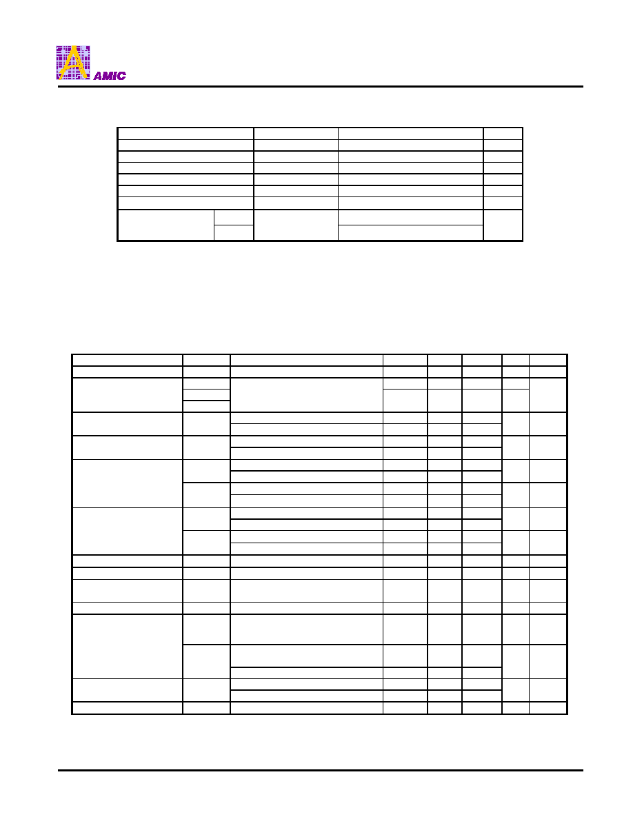
DC Characteristics
1. Electrical Characteristics
(Unless otherwise specified: VDD = +5.0
�
0.5V, VSS =0V, Ta = -30 to 85
�
C)
Parameter
Symbol
Conditions
Min.
Typ.
Max.
Unit Note
Operating Voltage
VDD
+2.4
-
+5.5
V
1
V5
+2.7
-
+11
V
V1, V2
LCD Drive Voltage
V3, V4
When using an external LCD
Power supply
VSS
-
V5
V
2
VDD=+2.4 to +4.5V
0.8xVDD
-
VDD
High-level Input
Voltage
V
IH
VDD=+5.0
�
0.5V
0.8xVDD
-
VDD
V
3
VDD=+2.4 to +4.5V
VSS
-
0.2xVDD
Low-level Input
Voltage
V
IL
VDD=+5.0
�
0.5V
VSS
-
0.3xVDD
V
3
I
OH
=-0.5mA, VDD=+2.4 to+4.5V
0.8xVDD
-
-
V
OH1
I
OH
=-I.0 mA
0.8xVDD
-
-
V
4
I
OH
=-50
�
A, VDD=+2.4 to+4.5V
0.8xVDD
-
-
High-level Output
Voltage
V
OH2
I
OH
=-120
�
A
0.8xVDD
-
-
V
OSCO
5
I
OL
=0.5mA, VDD=+2.4 to +4.5V
-
-
0.2xVDD
V
OL1
I
OL
=1.0mA
-
-
0.2xVDD
V
4
I
OL
=50
�
A VDD=+2.4 to +4.5V
-
-
0.2xVDD
Low-level Output
Voltage
V
OL2
I
OL
=120
�
A
-
-
0.2xVDD
V
OSCO
Input Leakage Current
I
ILEAK
VDD=+2.4 to +5.5V
-1.0
-
1.0
�
A
5
Output Leakage Current
I
OLEAK
VDD=+2.4 to +5.5V
-3.0
-
3.0
�
A
6
LCD Driver
ON Resistor
R
ON
Ta=25
�
C, V5=+8.0V
1/5 Bias
-
3.0
5.0
K
7
Standby Current
I
S
-
0.05
5.0
�
A
8
I
SS1
External LCD power supply is used:
During LC display V5=+8.0 V
Rf= 1 M
-
20.0
30.0
�
A
9
During access: tcyc=200 KHz
VDD=+3.0
�
0.3 V
-
150
450
Operating Current
l
SS2
During access: tcyc=200 KHz
-
300
�
A
10
Rf=1.0M
VDD=+3.0V
11
16
21
Oscillating
Frequency
f
OSC
Rf=1.0M
VDD=+5.0V
15
18
22
KHz
11
Wait Time
t
R
10
-
-
�
s
12

A31W33128 Series
PRELIMINARY (December, 2000, Version 0.1)
24
AMIC Technology, Inc
2. LCD Power Supply Circuit Electrical Characteristics
(Unless otherwise specified: VDD = +2.4V to +5.5V, VSS = 0V, Ta = -30 to 85
�
C)
Parameter
Symbol
Conditions
Min.
Typ.
Max.
Unit Note
Operating Voltage
VDD
+2.4
-
+5.5
V
13
Boosting Output
Voltage
V
OUT
Triple boosting: Up to VDD=3.6V
Double boosting: Up to VDD=5.5V
-
-
+11.0
V
1/4 Bias
+4.0
-
+11.0
1/5 Bias
+4.5
-
+11.0
LCD Supply Circuit
Operating Voltage
V5
1/6.7 Bias
+5.5
-
+11.0
V
14
LCD Driver
Operating Voltage
V
LCD
+2.7
-
+11.0
V
15
Built-in LCD Circuit
Current Consumption
I
SSL
V
OUT
=+10.0 V Double Boosting
VDD=+5.0 V
V5=8.0V 1/5 Bias
Osc. Frequency : 18 KHz
-
+90
+200
�
A
16
External LCD Power
Supply Used: LCD Drive
Current Consumption
l
V5
V5=8.0V 1/5 Bias
-
+30
+75
�
A
17
VREF=+0.01%/
�
C
+2.0
+2.2
+2.4
Reference Voltage
V
REF
Ta=25
�
C
VREF=-0.13%/
�
C
+1.3
+1.5
+1.7
V
18
Reference Current
I
REF
Fine adjustment data (1111)
Ta=25
�
C
1.5
2.5
4.0
�
A
19
V1
1/4
*
V5-0.1 1/4
*
V5
1/4*V5+0.1
V2
2/4
*
V5-0.1 2/4
*
V5
2/4*V 5+0.1
V3
2/4
*
V5-0.1 2/4
*
V5
2/4*V 5+0.1
LCD
Drive bias voltage
(1/4 bias)
V4
V5=+4.0V to +11.0V
3/4
*
V5-0.1 3/4
*
V5
3/4*V 5+0.1
V1
1/5
*
V5-0.1 1/5
*
V5
1/5*V 5+0.1
V2
2/5
*
V5-0.1 2/5
*
V5
2/5*V 5+0.1
V3
3/5
*
V5-0.1 3/5
*
V5
3/5*V 5+0.1
LCD
Drive bias voltage
(1/5 bias)
V4
V5=+4.5V to +11.0V
4/5
*
V5-0.1 4/5
*
V5
4/5*V 5+0.1
V1
1/6.75
*
V5-0.1
1/6.75
*
V5
1/6.75*V 5+0.1
V2
2/6.75
*
V5-0.1
2/6.75
*
V5
2/6.75*V 5+0.1
V3
4.75/6.5
*
V5-0.1
4.75/6.75
*
V5
4.75/6.75*
V5+0.1
LCD
Drive bias voltage
(1/6.75 bias)
V4
V5=+5.5V to +11.0V
5.75/6.75
*
V5-0.1
5.75/6.75
*
V5
5.75/6.75*
V+0.1
V
20
3. References
Parameter
Symbol
Conditions
Min.
Typ.
Max.
Unit
Note
Input Pin Capacity
C
IN
Ta=25
�
C
-
5
8
pF
3

A31W33128 Series
PRELIMINARY (December, 2000, Version 0.1)
25
AMIC Technology, Inc
Notes:
1. Sharp variation in the supply voltage or input signal voltage due to strange noises may lead to a malfunction of the IC.
Supply stable supply voltage and input signal voltage.
If you change the level of the supply voltage intentionally, a malfunction may occur. Never change the level of the supply
voltage.
2. When the external bias voltage is input, V5
V4, V3, V2, V1
VSS, V5
VDD. There is no limitation for determining the
voltage level of V1, V2, V3, and V4.
3. Pins A0,
CS
, E, R/W, C68/80, P/S, OSCI, FNC1 and FNC2.
Pins D0 to D7 during display data write and command input.
Fully swing the levels V
IH
and V
IL
of the input signal within the range of power supply voltage so that the state is V
IH
=VDD,
V
IL
=VSS. When the level of V
IH
and V
IL
is the middle level of the supply voltage, the through current flowing through the
input pin and the current consumption may be increased.
4. Pins D0 to D7 during read.
5. Pins A0
CS
, E, R/W, C68/80, P/S, OSCI, FNC1 and FNC2.
6. Pins D0 to D7 during write and high-impedance.
7. ON resistance between LCD drive output pins (SEG1 to SEG128, COM1 to 32, COMICN1, and 2) and LCD drive bias
voltage pins (VI, V2, V3, V4). Using the external LCD power supply, measure the resistance at a 0.1-V difference from the
LCD drive output pin after applying 1/2 voltage of V5 to the LCD drive bias voltage pin.
8. Power save state. When turning the input pin to "Floating," the through current flows and will eventually the power save
effect may be reduced.
9. Shows the current consumption during display including CR oscillation.
It does not include the current consumed by the booster, LCD supply voltage adjustment circuit, voltage regulator, LCD
bias resistor when using the external LCD power supply. The LCD drive output pin is no load. The current consumed by
the LCD panel and wiring capacitor is not included. Measure it without access from the MPU. The current consumed by
the external LCD power supply and external bias resistor and other is not included.
10. The current consumption while the checkered pattern display data are being written from the MPU. The CR oscillation is
measured while the CR oscillating circuit stops. The voltage level of the input signal is the V
IH
=VDD and V
IL
=VSS. When
the input signal voltage is in the middle level, the current consumption may be increased. When the display data is written
from the MPU during display, the state is changed to I
SS1
+l
SS2
.
11. Shows the standard value at oscillating resistor 1M
. Determine appropriate oscillating frequency so as not to be in
synchronization with the frame frequency and other frequency such as the fluorescent lamps.
12. Shows the wait time from when the power voltage rises to 80 of the specified voltage to when the command input
becomes available.
13. The operating voltage range of the booster.
14. Shows the operating voltage range of the LC voltage adjustment circuit, voltage follower, and LCD bias resistor. The
operating voltage range differs depending upon each bias setting value. To adjust V5 with the LCD voltage adjustment
circuit, it is necessary to set the voltage within the bias voltage. IV5I - IV
OUT
I
0.2V.
15. The operating voltage range of the LCD driver after the voltage follower functions. Also, it shows the voltage range of V1 to
V5 supplied from the external LCD power supply circuit.
16. Shows the value of the current consumed by the booster, LCD voltage adjustment circuit, voltage follower, LCD bias
resistor, and LCD driver. It does not include the value IRREG=V5/(R1+R2+R3) of the current flowing through external
resistors R1, R2, and R3. Set the command fine adjustment data to 1000. Outputs the checkered patterns from the LCD
drive output pin. The pin is measured at "Open." Current consumption of the IC during display is I
SSL
+l
SS1
.
17. The built-in LCD power supply circuit stops when FNC1 and 2 are "H." Current consumption only for the LCD driver.
Outputs the checkered patterns from the LCD drive output pin. The pin is measured at "Open." Current consumption of the
IC during display is IV5+ l
SS1.
When using the external power supply, stop the built-in power supply circuit which does not need to be operated with pins
FNC1 and 2 to prevent the IC from being broken due to a shorting of the internal power supply.
18. The reference voltage differs depending upon the temperature coefficient selected with the corresponding command.
19. Constant current which flows into the LCD Voltage Command Fine Adjustment Circuit of the IC, for the Fine adjustment
data (1111).
Increasing the Fine adjustment data by 1 bit, V5 increases by Rb x I
REF
/15.
20. For the Chips deliveries, chips are delivered after they satisfy their LCD drive bias voltages are 0.08V in the delivery testing
at 25
�
C.

A31W33128 Series
PRELIMINARY (December, 2000, Version 0.1)
26
AMIC Technology, Inc
Timing Characteristics
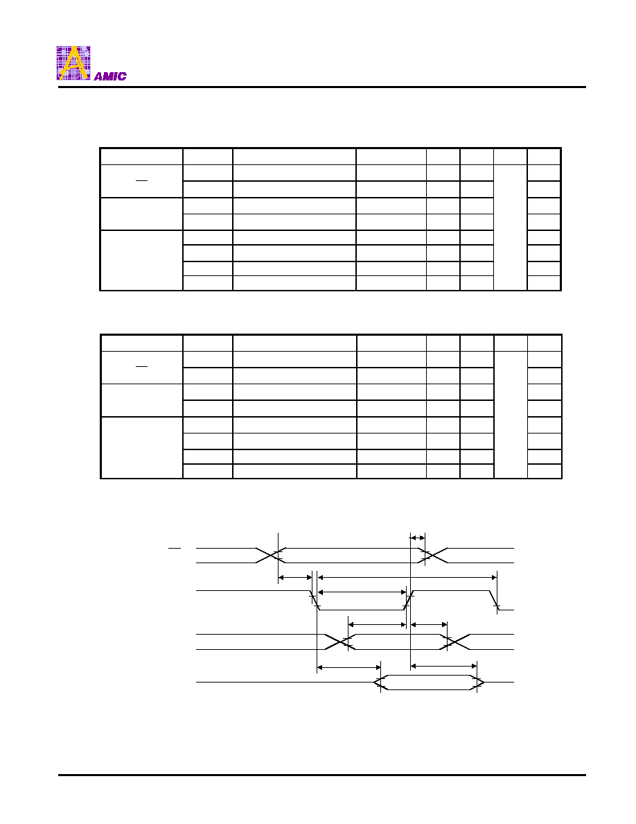
1. Parallel Interface
1.1 68-Series MPU Read/Write Timing Interface Characteristics
68-Series MPU Read/Write Timing Characteristics
(Ta=-30 to 85
�
C, VDD=+5V
�
10%)
Signal
Symbol
Designation
Conditions
Min. Max.
Unit
Note
t
CYC6
System Cycle Time
500
-
t
AH6
Address Hold Time
20
A0
CS
, R/W
t
AW6
Address Setup Time
20
t
DS6
Data Setup Time
80
-
t
DH6
Data Hold Time
20
-
t
ACC6
Access Time
CL=15 pF
90
D0 to D7
t
OH6
Output Disable Time
CL=15 pF
10
60
READ
100
-
E
t
EW
Enable Pulse Width
WRITE
80
-
ns
68-Series MPU Read/Write Timing Characteristics
(Ta=-30 to 85
�
C, VDD=+3V
�
10%)
Signal
Symbol
Designation
Conditions
Min. Max.
Unit
Note
t
CYC6
System Cycle Time
1000
-
t
AH6
Address Hold Time
40
-
A0
CS
, R/W
t
AW6
Address Setup Time
40
-
t
DS6
Data Setup Time
160
-
t
DH6
Data Hold Time
40
-
t
ACC6
Access Time
CL=15 pF
180
D0 to D7
t
OH6
Output Disable Time
CL=15 pF
10
120
READ
200
-
E
t
EW
Enable Pulse Width
WRITE
160
-
ns
Note :
�
Rise/fall time of the input signal is 15 nsec or less.
�
Timing is specified at 20% or 80% of the signal waveform.
t
AW6
E
D0 to D7
(WRITE)
R/W
A0, CS
DB0 to DB7
(READ)
t
ACC6
t
AH6
t
DH6
t
DS6
t
OH6
t
EW
t
CYC6
A31W33128 Series
PRELIMINARY (December, 2000, Version 0.1)
27
AMIC Technology, Inc
1.2 80-Series MPU Read/Write Timing Characteristics
80-Series MPU Read/Write Timing Characteristics
(Ta=-30 to 85
�
C, VDD=+5V
�
10%)
Signal
Symbol
Designation
Conditions
Min.
Max.
Unit
Note
t
AH8
Address Hold Time
20
-
A0
CS
t
AW8
Address Setup Time
20
-
t
CYC8
System Cycle Time
500
-
R/W, E
t
CC8
Control Pulse Width
100
-
t
DS8
Data Setup Time
80
t
DH8
Data Hold Time
20
-
t
ACC8
E Access Time
CL=15 pF
90
D0 to D7
t
OH8
Output Disable Time
CL=15 pF
10
60
ns
80-Series MPU Read/Write Timing Characteristics When VDD=+3V
(Ta=-30 to 85
�
C, VDD=+3V
�
10%)
Signal
Symbol
Designation
Conditions
Min.
Max.
Unit
Note
t
AH8
Address Hold Time
40
-
A0
CS
t
AW8
Address Setup Time
40
-
t
CYC8
System Cycle Time
1000
-
R/W, E
t
CC8
Control Pulse Width
200
-
t
DS8
Data Setup Time
160
-
t
DH8
Data Hold Time
40
-
t
ACC8
E Access Time
CL=15 pF
180
D0 to D7
t
OH8
Output Disable Time
CL=15 pF
10
120
ns
Note :
�
Rise/fall time of the input signal is 15 nsec or less.
�
Timing is specified at 20% or 80% of the signal waveform.
t
AH8
t
AW8
t
CYC8
t
CC8
t
DS8
t
DH8
t
OH8
t
ACC8
A0, CS
R/W, E
D0 to D7
(WRITE)
D0 to D7
(READ)

A31W33128 Series
PRELIMINARY (December, 2000, Version 0.1)
28
AMIC Technology, Inc
2. Serial Interface
Serial Interface Timing Characteristics
(Ta=-30 to 85
�
C, VDD=+5V
�
10%)
Signal
Symbol
Designation
Conditions
Min.
Max.
Unit
Note
t
CSS
Chip Select Setup Time
50
CS
t
CHS
Chip Select Hold Time
400
t
ASS
Address Setup Time
120
A0, R/W
t
AHS
Address Hold Time
200
t
DSS
Data Setup Time
120
D0
(SDI)
t
DHS
Data Hold Time
50
t
CYCS
Clock Cycle Time
500
t
CLLS
Clock L Time
200
D1
(SCLK)
t
CLHS
Clock H Time
200
t
DDS
Data Delay Time
CL=15 pF
90
D2
(SDO)
t
OHS
Data Disable Time
CL=15 pF
10
60
ns
1
Serial Interface Timing Characteristics
(Ta=-30 to 85
�
C, VDD=+3V
�
10%)
Signal
Symbol
Designation
Conditions
Min.
Max.
Unit
Note
t
CSS
Chip Select Setup Time
100
CS
t
CHS
Chip Select Hold Time
800
t
ASS
Address Setup Time
240
A0, R/W
t
AHS
Address Hold Time
400
t
DSS
Data Setup Time
240
D0
(SDI)
t
DHS
Data Hold Time
100
t
CYCS
Clock Cycle Time
1000
t
CLLS
Clock L Time
400
D1
(SCLK)
t
CLHS
Clock H Time
400
t
DDS
Data Delay Time
CL=15 pF
180
D2
(SDO)
t
OHS
Data Disable Time
CL=15 pF
10
120
ns
1
Note : 1. D2(DSO) is high-impedance at the rising edge of the
CS
.
2. Rise/fall time of the signal is 15 nsec. or less
3. Timing is specified at 20% or 80% of the signal waveform.
Serial Interface Read/Write Timing Characteristics
D1
(SCLK)
R/W
CS
t
CHS
t
AHS
t
OHS
t
CS
t
ASS
t
CLLS
t
CYCS
t
CLHS
t
DDS
t
DSS
t
DHS
A0
D0
(SDI)
D2
(SDO)

A31W33128 Series
PRELIMINARY (December, 2000, Version 0.1)
29
AMIC Technology, Inc
Examples of Applications of LCD Power Supply
Reference
C : 1.0
�
F
C1 : 0.47
�
F
C2 : 0.1
�
F
C3 : 0.01
�
F
Capacitor C3 connected to V3 pin is recommended 0.01
�
F
. When Using a Built-in LCD Power
Supply Circuit (Triple Boosting)
VSS
C
C
C
VSS
C1+
C1-
C2+
C2-
V
OUT
Rf
OSC OSC2
VDD
VDD
C
R1
R2
R3
VSS
VSS
V1
V2
V3
V4
VSS
FNC1
FNC2
V
CNT
V5
. When Using an External Regulator
. When Using an External Boosting Power Supply
VSS
VSS
C1+
C1-
C2+
C2-
V
OUT
Rf
OSC OSC2
VDD
VDD
C
R1
R2
R3
VSS
VSS
V1
V2
V3
V4
VSS
FNC1
FNC2
V
CNT
V5
External Boosting
Power Supply
C
VDD
VSS
VSS
C1+
C1-
C2+
C2-
V
OUT
Rf
OSC OSC2
VDD
VDD
C
VSS
VSS
V1
V2
V3
V4
FNC1
FNC2
V
CNT
V5
External
Regulator
C
VDD
. When Using an External LCD Power Supply
VSS
VSS
C1+
C1-
C2+
C2-
V
OUT
Rf
OSC OSC2
VDD
VDD
VSS
V1
V2
V3
V4
FNC1
FNC2
V
CNT
V5
V
LC
VSS
VSS
VDD
C
C
C
C
C
C
C
C
C
C
C
C
A31W33128 Series
PRELIMINARY (December, 2000, Version 0.1)
30
AMIC Technology, Inc
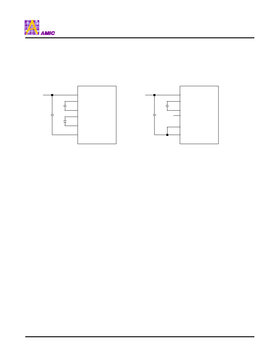
�
Booster Capacitor Connection
Reference
C : 1.0
�
F
C1 : 0.47
�
F
Tripler
Doubler
VSS
C1
C1
C
VS
C1-
C1+
C2-
C2+
V
OUT
VSS
C1
C1
Open
VS
C1-
C1+
C2-
C2+
V
OUT
A31W33128 Series
PRELIMINARY (December, 2000, Version 0.1)
31
AMIC Technology, Inc
Examples of Connection to LCD Panels
2. 1/33 Duty 17 X 256 Panel
1. 1/17 Duty 17 X 128 Panel
. COM1 to 16 are used:
LCD17 X 128
1........128
Icon
Icon
....1
16
SE
A31W33128
COM ICN2
COM ICN1
COM
1 to 16
. COM17 to 32 are used:
LCD17 X 128
1........128
Icon
Icon
SE
A31W33128
COM ICN2
COM ICN1
....1
16
COM
17 to 32
LCD17 X 256
1........128
Icon
Icon
SE
A31W33128
COM ICN2
COM ICN1
....17
32
COM
17 to 32
COM
1 to 16
....
1
16
129........256

A31W33128 Series
PRELIMINARY (December, 2000, Version 0.1)
32
AMIC Technology, Inc
3. 1/33 Duty 33 X 128 Panel
3.1 Normal Common Output
3.2 Common Right/Left Alternate Output
Output in a numerical order
of common pin Nos.
Even-Numbered Common Line
Uneven-Numbered Common Line
LCD
33 X 128
1........128
Icon
Icon
SE
A31W33128
COM ICN2
COM ICN1
....1
16
....17
32
COM
1 to 16
COM
17 to 32
LCD
33 X 128
1........128
Icon
Icon
SE
A31W33128
COM ICN2
COM ICN1
....
1
3
29
31
COM
1 to 16
COM
17 to 32
....
2
4
30
32
Examples of Connection to LCD Panels (continued)

A31W33128 Series
PRELIMINARY (December, 2000, Version 0.1)
33
AMIC Technology, Inc
Ordering Information
Part No.
Package
A31W33128C
COG
A31W33128T
TCP