 | –≠–ª–µ–∫—Ç—Ä–æ–Ω–Ω—ã–π –∫–æ–º–ø–æ–Ω–µ–Ω—Ç: AT43311 | –°–∫–∞—á–∞—Ç—å:  PDF PDF  ZIP ZIP |

AT43311
1
Features
∑
Self-Powered Hub with Bus Power Controller
∑
Full Compliance with USB Spec Rev 1.0
∑
Full Speed USB Host Interface
∑
Four Downstream Ports
∑
Downstream Support for Full Speed and Low Speed Transfer Rates
∑
Continual Monitoring of Port by System Host
∑
Individual Port Power Control
∑
USB Connection Status Indicators
∑
6 MHz Oscillator with On-Chip PLL
Description
The AT43311 is a fully compliant USB hub chip with 5 ports, one upstream port and
four full/low-speed downstream ports. The AT43311 can be used as a stand alone or
can provide a simple and quick method of adding USB ports to an existing device.
As a repeater, the AT43311 provides upstream connectivity between the selected
function and the host. Connectivity involves setting up and tearing down connections,
handling bus faults, recovering from bus faults and detecting downstream device con-
nections and disconnections.
The AT43311 may also act as a hub controller managing the hub operations and
recording the status of the hub, bus transactions, and downstream ports. In this mode,
the AT43311 tracks and generates the bus enumeration, provides configuration infor-
mation to the host, provides individual port status to the host, and controls the port
operation based on host commands.
0738A-A
USB Hub
AT43311
Preliminary
Pin Configurations
SOIC/DIP/Cerdip
1
2
3
4
5
6
7
8
9
10
11
12
13
14
15
16
32
31
30
29
28
27
26
25
24
23
22
21
20
19
18
17
PWR2
PWR3
PWR4
VCC5
VSS
OSC1
OSC2
LFT
VCCA
OVL4
OVL3
OVL2
OVL1
VREF
GND
STAT4
PWR1
DP4
DM4
DP3
DM3
GND
DP2
DM2
VCC3
DP1
XDM1
DP0
DM0
STAT1
STAT2
STAT3
AT43311
2
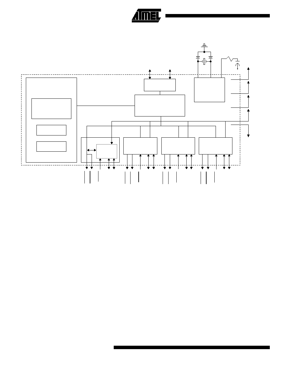
Block Diagram
Note:
1.
This document assumes that the reader is familiar with the Universal Serial Bus and therefore only describes the unique
features of the AT43311 chip. For detailed information about the USB and its operation, the reader should refer to the Uni-
versal Serial Bus Specification Version 1.0, January 19, 1996.
PORT 1
PORT 2
PORT 3
PORT 0
PORT 4
HUB
REPEATER
TIMING
AND
CONTROL
Serial Interface
Engine
HUB CONTROLLER
LFT
OSC2
OSC1
DM0
DP0
VCC5
VCC3
VCCA
VREF
GND
S
TAT
1
S
TAT
2
S
TAT
3
S
TAT
4
PWR1
PWR2
PWR3
PWR4
O
VL1
O
VL2
O
VL3
O
VL4
DM1
DM2
DM3
DM4
DP1
DP2
DP3
DP4
Endpoint 0
Endpoint 1
Overcurrent
Protection/
Reporting

AT43311
3
Pin Description
Pin Description
Pin Type
Description
OSC1
I
Oscillator Input. Input to the inverting 6 MHz oscillator amplifier.
OSC2
O
Oscillator Output. Output of the inverting oscillator amplifier.
LFT
I
PLL Filter. For proper operation of the PLL, this pin should be connected through a
100
resistor and 10 nF capacitor to ground (V
SS
) in parallel with a 2.2 nF capacitor
(see Figure 1≠Power Supply Connection).
VREF
I
Reference Voltage. This is an input pin that should be connected to an external
voltage source. VREF is used internally as the reference voltage by the overload
protection circuit to decide whether there is a problem with a port's power supply.
DP0
B
Upstream Plus USB I/O. This pin should be connected to VCC3 through an external
1.5K
pullup resistor. DP0 and DM0 form the full speed differential signal pin pairs
connected to the Host Controller or an upstream Hub.
DM0
B
Upstream Minus USB I/O
DP[1:4]
B
Port Plus USB I/O. These pins should be connected to VSS through external 1.5K
resistors. DP[1:4] and DM[1:4] are the differential signal pin pairs to connect
downstream USB devices.
DM[1:4]
B
Port Minus USB I/O. These pins should be connected to VSS through external 15K
resistors. DP[1:4] and DM[1:4] are the differential signal pin pairs to connect
downstream USB devices.
OVL[1:4]
I
Port Overload. These are the input signals used to indicate to the AT43311 that there
is a power supply problem with the port. If OVL is asserted, the AT43311 will assert
the corresponding PWR[1:4] pin and report the status to the USB Host.
PWR[1:4]
OD
Power Switch. These are the output signals used to enable or disable the external
voltage regulator supplying power to the port. PWR[1:4] is de-asserted when a power
supply problem is detected at OVL[1:4].
For proper operation of PWR[1:4], an external pull-up resistor of 10K
to VCC5 is
required.
STAT[1:4]
O
Connect Status. These are output pins indicating that a port is properly connected.
STAT[1:4] is asserted when the port is enabled.
V
CC3
V
3.3V Power Supply, used for the USB interface
V
CC5
V
5V Power Supply, main power supply for the AT43311
V
CCA
V
5V Analog Power Supply
GND
V
Ground

AT43311
4
USB Hub Description
Hub Repeater
The hub repeater is responsible for port connectivity setup
and tear-down. The repeater also supports exception han-
dling such as bus fault detection and recovery, and con-
nect/disconnect detection.
When a SOP token is detected on the upstream port,
Port0, the AT43311 determines the speed of the transfer.
A USB hub must not propagate a full speed transfer to a
low speed port due to the possible misinterpretation of the
data. The AT43311 will propagate the packet to all enabled
downstream ports.
Note: See USB Specification for further detail on bus
states
The AT43311 supports downstream data signaling at both
1.5 Mbps and 12 Mbps. Devices attached to the down-
stream ports are either full speed or low speed depending
on which data line (DP or DM) is pulled high. If a port is
enumerated as low speed, the output buffers operate at a
slew rate between 75 ns and 300 ns. The AT43311 will not
propagate any traffic to that port unless it is prefaced with a
preamble PID. Low speed data following the preamble PID
is propagated to both low and full speed devices. The
AT43311 will enable low speed drivers within four full-
speed bit times of the last bit of a preamble PID, and will
disable the drivers at the end of an EOP. The upstream
traffic from any port to the host is propagated by Port0
using the full speed 4-20 ns slew rate drivers.
All ports are independently driven and monitored on the DP
and DM pins. The AT43311 detects or generates the `J',
`K', and SE0 bus signaling states. Each hub port has sin-
gle-ended and differential receivers on its DP and DM lines.
The ports' I/O buffers comply to the voltage levels and drive
requirements as specified in the USB Specifications Revi-
sion 1.0.
The Hub Repeater implements a frame timer that is timed
by the 12 MHz USB clock and is reset every time an SOF
token is received from the Host.
Hub Controller
The hub controller manages and records the operations of
the AT43311. During enumeration, the controller sends the
host the configuration information. The controller also
allows the host to retrieve the status of the downstream
ports, and power the downstream ports. The controller
applies power to the downstream ports on a per port basis.
After configuration, the controller will enable the power to a
downstream port upon a SetPortPower command by the
host. The controller supports two endpoints and a Control
Status register.
Serial Interface Engine
The Serial Interface Engine (SIE) converts data between
the serialized USB format and usable data for the controller
and repeater. To carry out these tasks, the SIE is able to
detect or generate USB signaling. Once a valid operation is
detected, the SIE translates the data depending on the
operation.
During a reception, the SIE will use the high speed clock
supplied by the PLL to help synchronize and separate the
synchronization information from the data. The data must
be decoded before the SIE may supply the packet ID to the
controller and repeater.
The USB protocol uses Cyclical Redundancy Check
(CRC), Non Return to Zero Invert (NRZI) data encoding
and bit stuffing to improve the reliability of data transfers.
The SIE must decode the NRZI and strip off the stuffed bit
to determine the actual data. The CRC information will be
used by the SIE to determine if a transmission error has
occurred. If an error has occurred, the SIE will correct the
data using CRC algorithms.
Control Status Register
Bit
Function
Value
Description
0
Hub configuration status
0
1
Set to 0 or 1 by a Set_Configuration Request
Hub is not currently configured
Hub is currently configured
1
Hub remote wakeup status
0
1
Set to 0 or 1 by ClearFeature or SetFeature request
Default value is 0
Hub is currently not enabled to request remote wakeup
Hub is currently enables to request remote wakeup
2
Endpoint0 STALL status
0
1
Endpoint0 is stalled
Endpoint0 is stalled
3
Endpoint1 STALL status
0
1
Endpoint1 is not stalled
Endpoint1 is stalled

AT43311
5
Status Change Register
Bit
Function
Value
Meaning
0
Hub status change
0
1
No change in status
Change in status detected
1
Port1 status change
0
1
No change in status
Change in status detected
2
Port2 status change
0
1
No change in status
Change in status detected
3
Port3 status change
0
1
No change in status
Change in status detected
4
Port4 status change
0
1
No change in status
Change in status detected
5-7
Reserved
0
Default values
Endpoint0
Endpoint0 is the AT43311's default endpoint used for enu-
meration of the Hub and exchange of configuration infor-
mation and requests between the Host and the AT43311.
Endpoint0 supports control transfers.
Standard USB Device Requests and class-specific Hub
Requests are supported through Endpoint0.
The Hub Controller supports the following descriptors
through Endpoint0 (Descriptors are described in detail in
the Descriptors Section of this document):
∑ Device Descriptor
∑ Configuration Descriptor
∑ Interface Descriptor
∑ Endpoint Descriptor
∑ Hub Descriptor
Endpoint1
Endpoint1 is used by the Hub Controller to send status
change information to the Host. Endpoint1 supports inter-
rupt transfers.
The Hub Controller samples the changes at the end of
every frame at time marker EOF2 in preparation for a
potential data transfer in the subsequent frame. The sam-
pled information is stored as a byte in Status Change Reg-
ister using a bitmap scheme.
Each bit in the Status Change Register corresponds to one
port as shown below.
An IN Token packet from the Host to Endpoint1 indicates a
request for port change status. If the Hub has not detected
any change on the ports or any changes in the hub itself,
then all bits in this register will be 0 and the Hub Controller
will return a NAK to requests on Endpoint1. If a change in
the port status exists, the Hub Controller will transfer the
whole byte. The Hub Controller will continue to report a sta-
tus change when polled until that particular change has
been removed by a ClearPortFeature request from the
Host. No status change will be reported by Endpoint1 until
the AT43311 has been enumerated and configured by the
Host through Endpoint0.
Power Management
The AT43311 is designed to be powered from the USB
bus. As such, the power consumption for the AT43311
itself is less than 100 mA. However, downstream devices
require separate power supplies. The AT43311 monitors
and controls each power supply to the individual down-
stream devices.
Careful design and selection of the power switch is
required to meet the USB specification. The USB specifica-
tions requires that the voltage drop at the power switch be
no more than 100 mV. USB requirements specify that a
downstream device may use a maximum of 500 mA. These
conditions are best met by using a MOSFET switch with an
on resistance of 200 m
or less.
As a sample power circuit, consider a P-channel enhance-
ment mode MOSFET. The condition of the port's power is
monitored at the output side of the PMOS switch which is
connected to the port's OVL[1:4] pin. During an overcurrent
condition, the MOSFET switch's internal resistance causes
the MOSFET's output voltage to drop at the OVL[1:4] pin. If
the MOSFET's output voltage drops to less than the volt-
age at the VREF voltage reference pin, the AT43311 inter-
prets this drop as an overcurrent condition. The AT43311
does internal filtering to make sure that spurious or switch-
ing transients are ignored. If an overcurrent condition
exists, the AT43311 removes the power from that port by
de-activating the port's PWR[1:4] pin and reports the condi-
tion to the Host.