
1
Features
∑
Software Module Dedicated to Voice Processing and Multi-way Conferencing
∑
Optimized for the AT75 Series Smart Internet Appliance Processor (SIAP
TM
)
∑
Includes Several Run-time Configurable Stand-alone Algorithms
≠ G.723.1 Dual-rate Vocoder (5.3 Kbps/6.4 Kbps)
≠ VAD/CNG Silence Compression (Annexe A of G.723.1)
≠ G.711 µ-law or A-law Compression (64 Kbps)
≠ Arbitrary Tone Generator
≠ DTMF Detector
≠ Echo Canceller
∑
ITU-T G.723.1 and G.711 Standard-compliant
∑
Either up to Two Decode Channels with G.723.1 Standard, or up to Four Decode
Channels with G.711 Standard
∑
Available with a uClinux
Æ
Device Driver
Overview
The AT75C1212 Multi-way Conferencing Software Module is designed to run on the
OakDSPCore
Æ
subsystem of the AT75 series Smart Internet Appliance Processor. It
implements commonly-used voice processing algorithms:
∑
Low bit-rate G.723.1 vocoder for multimedia communication.
∑
Silence compression algorithm to efficiently handle periods of silence during
communication.
∑
High bit-rate voice compression algorithm.
∑
Arbitrary tone generator that can be used to generate any dual-tone or single-tone
frequency during a programmable duration.
∑
DTMF detector to decode incoming DTMF signaling.
∑
An echo canceller that eliminates the near-end echo.
The implemented algorithms have a number of parameters which can be programmed
at run time. These parameters modify the behavior of the DSP algorithms in such a
manner that they comply with the applicable standards under most situations. They
also allow the AT75C1212 to cope with many non-standard situations often encoun-
tered on private telephone infrastructures.
Moreover, the AT75C1212 module is able to perform multi-way conferencing. Either up
to two independent decode channels with G.723.1 or up to four decode channels with
either µ-law or A-law compression are available with no penalty on the voice quality.
The AT75C1212 takes advantage of the AT75 mailbox to exchange data with the on-
chip ARM7TDMI
Æ
core. The organization of the data communication channel makes it
easy to integrate the AT75C1212 interface into most operating systems.
For developers using uClinux, a specific device driver is supplied, thereby assuring the
extension of uClinux capabilities to the complete functionality of the AT75C1212 mod-
ule in a seamless manner.
This document is made up of three sections:
1.
Functional description of the supported algorithms.
2.
Description of the low level software interface.
3.
Description of the uClinux device driver and full integration of AT75C1212
functionality.
Note:
Mixing low-level and driver-level programming should be avoided.
Smart Internet
Appliance
Processor
(SIAP
TM
)
AT75C1212
Multi-way
Conferencing
Software
Module
Rev. 2663A≠INTAP≠07/02

2
AT75C1212
2663A≠INTAP≠07/02
Functional
Description
A functional block diagram of the AT75C1212 Multi-way Conferencing Software Module
is given in Figure 1.
Figure 1. Block Diagram
G.723.1 Dual Rate
Vocoder
This algorithm can be used for compressing the speech or other audio signal compo-
nents of a multimedia service at a very low bit rate. This coder has two bit rates
associated with it: 5.3 and 6.4 Kbps. The higher bit rate has better quality; it is based on
Multi Pulse Maximum Likelihood Quantization (MP-MLQ) technique. The lower bit rate
gives good quality and provides system designers with additional flexibility. This rate is
based on an Algebraic Code Linear Pre-diction (ACELP) technique.
This coder operates on 30 ms speech frames of 16-bit linear PCM samples (sampling
frequency is 8 kHz). An algorithmic delay of 7.5 ms is to be taken into account before
getting an encoded voice data frame. That leads to a total delay of 37.5 ms. The result-
ing encoded frames are 20 bytes long for 5.3 Kbps rate and 24 bytes long for 6.4 Kbps
rate. The encoding rate can be chosen by means of a configuration command sent to
the DSP. (See "Request Notification Messages" on page 9.)
VAD/CNG
Voice Activity Detection (VAD) and Comfort Noise Generator (CNG) algorithms are
designed to work hand-in-hand with the G.723.1 vocoder. Silence compression tech-
niques are used to reduce the transmitted bit rate during silent intervals of speech. The
VAD side detects those silent intervals. CNG is used to produce a noise that matches
the actual background noise. CNG uses information provided by VAD to encode silent
intervals into Silence Insertion Descriptor (SID) frames that are 4 bytes long. It also re-
synthesizes 16-bit linear PCM samples of background noise with a SID frame input. The
VAD/CNG feature can be enabled or not by means of a configuration command sent to
the DSP. (See "Request Notification Messages" on page 9.)
G.711 µ-law and A-law
Voice Compression
µ-law and A-law are logarithmic compression techniques applied to speech signals.
They are done by simple operations that give no delay and excellent quality of speech.
However, the bit rate is very high (each 16-bit linear PCM speech sample gives an 8-bit
compressed sample leading to 64 Kbps) making this feature useful only for broadband
data networks. The compression/decompression algorithm can be chosen by means of
a configuration command send to the DSP. (See "Request Notification Messages" on
page 9.)
G.723.1 Encoder
+ VAD/CNG
G.711 µ-law/A-law
Encoder
G.711 µ-law/A-law Decoder
(Up to Four Intances)
G.723.1 Decoder + CNG
(Up to Two Intances)
DTMF
Detection
Tone Generation
ADC
DAC
To
Handset
From
Handset
Analog Signals
Digital Signals
Echo
Path
Echo
Cancellation
3
AT75C1212
2663A≠INTAP≠07/02
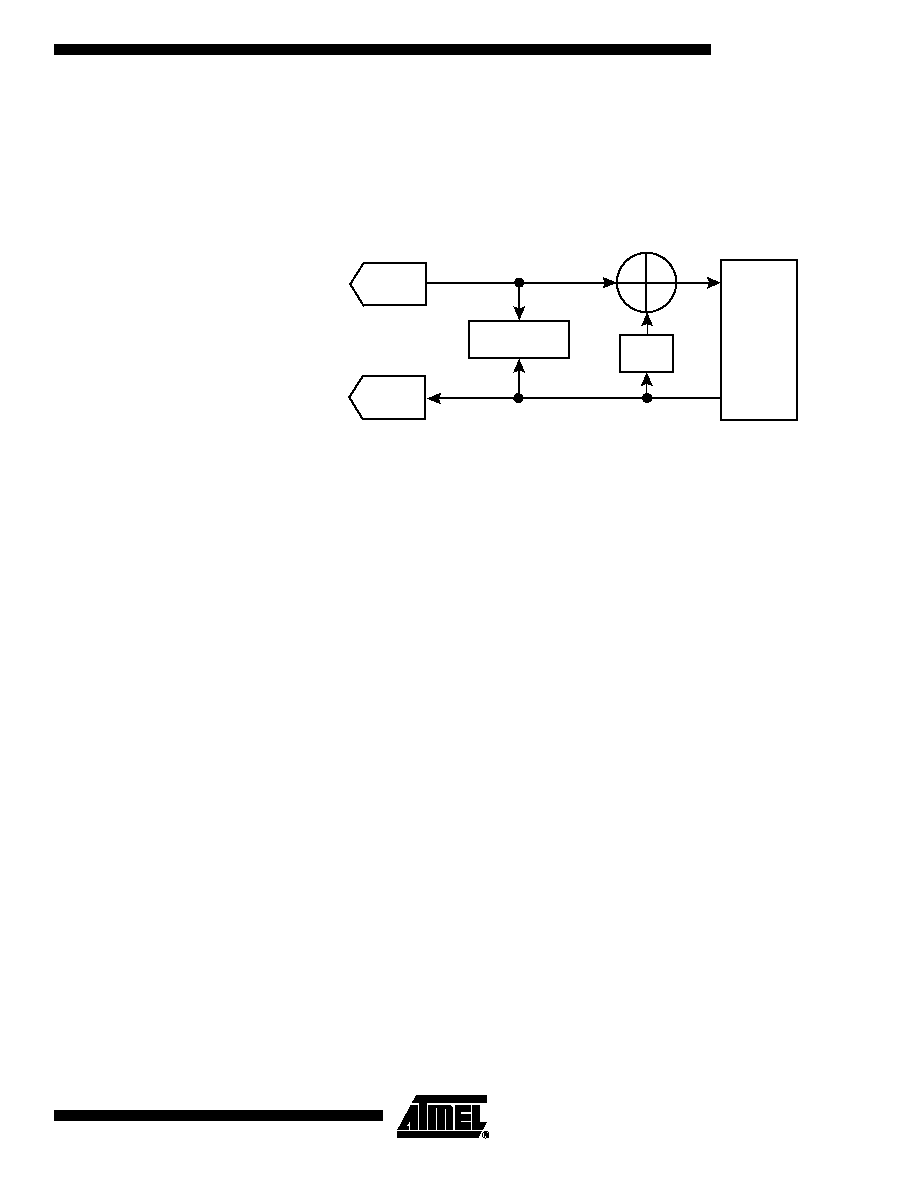
Echo Cancellation
Operation
The AT75C1212 contains an echo cancellation unit to eliminate near-end echo. This
unit is based on an adaptive FIR filter, which computes the expected echo and a sub-
tractor, which removes it from the transmitted signal. Since the echo characteristics can
slowly vary with time, an adaptive algorithm continuously updates the echo model.
A block diagram of the echo canceller is shown in Figure 2 below.
Figure 2. Block Diagram of Echo Canceller
Multi-way Conferencing
AT75C1212 module allows several decoding channels to be active at the same time (up
to two decode channels with G.723.1 standard or up to four with either PCM µ-law or
PCM A-law).
DTMF Detector
The DTMF detection task detects and decodes the 16 standard DTMF signals, in com-
pliance with the ITU-T Q.24 recommendation, with programmable threshold levels. The
application program, to comply with special (i.e. non-standard) situations, can tune
some parameters of the algorithm. In order to detect the DTMF signal, a bank of eight
resonant band pass filters is used. The central frequency of each filter corresponds to
one of the eight nominal values employed by standard DTMF generators. The power
level at each filter output is used to check for signal presence, signal condition require-
ments, and character condition requirements.
ADC
DAC
Adaptive
Algorithm
FIR
Other
Processing
Algorithms

4
AT75C1212
2663A≠INTAP≠07/02
Figure 3. DTMF Detector Block Diagram
The eight band pass filters are centered on the eight frequencies defined in the ITU-T
Q.24 specification. The bandwidth is specified according to the tolerance established in
this standard. Each filter rejects at least 20 dB of the other seven frequencies. The
power level is obtained by averaging the instantaneous energy during a window of 2 ms
for each of the eight filtered signals.
The detection of a DTMF signal requires that the following conditions be met:
∑
One frequency of each group is above a specified level.
∑
The power level difference between the low group tone and the high group tone is
within a given interval (twist).
∑
The power level of the highest tone of each group is above a specified level above
the other frequencies of the same group.
Signal
Condition
Detector
697 Hz
770 Hz
652 Hz
941 Hz
1209 Hz
1336 Hz
1477 Hz
1633 Hz
Power
Level
Power
Level
Power
Level
Power
Level
Power
Level
Power
Level
Power
Level
Power
Level
Out of Band
Rejection
Character
Condition
Status
Signal
In
5
AT75C1212
2663A≠INTAP≠07/02
The character condition is fulfilled when:
∑
The signal condition is preceded by a different character recognition condition or by
the continuous non-existence of a signal condition for a specified duration (silence).
∑
The signal condition for the same two tones exists continuously for a specified
duration. When the signal condition is satisfied for less than a specified duration, the
character is rejected. Once the character condition exists, it is unaffected by an
interval shorter than a specified duration.
Tone Generator
The tone generation task generates a pure sine wave or a dual tone with programmable
frequencies, amplitudes and duration.
Low Level Interface
This section describes how the AT75C1212 software is uploaded into the DSP sub-
system program memory. It also describes how the application software running on the
ARM and the AT75C1212 running on the DSP Subsystem exchange information
through Dual Port Mailboxes (DPMB).
This section assumes in-depth knowledge of the ARM/DSP Subsystem interface mail-
box system.
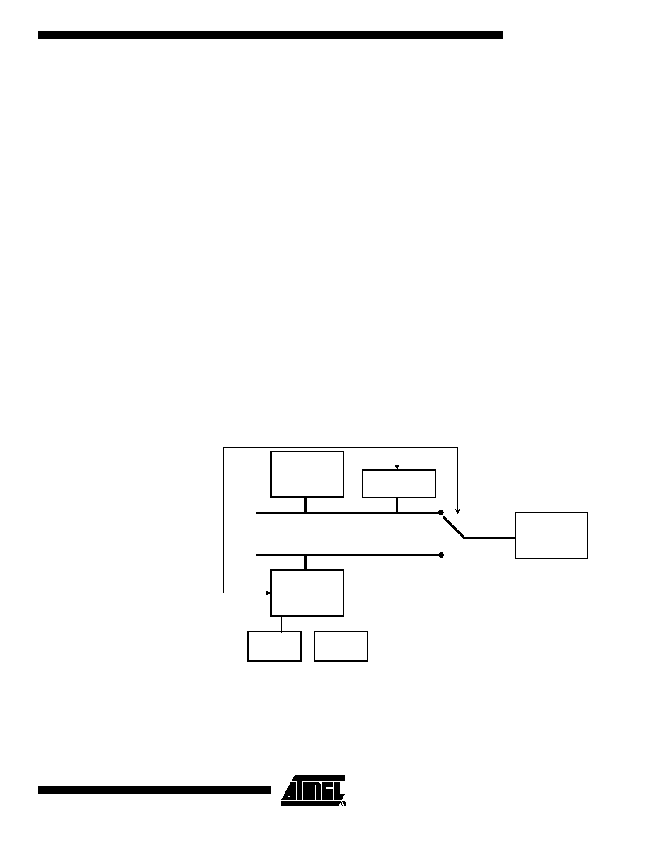
Voice Module Upload
While the DSP subsystem is held in reset, its program memory is made visible in the
ARM memory space. This allows the ARM application to write a binary image of the
DSP software very easily.
When the DSP subsystem is taken out of reset, its program memory is switched from
the ARM memory space back to the DSP program space just before the first instruction
is fetched. This process is illustrated in Figure 4.
Figure 4. Voice Module Upload
Note:
1. Bit RA in Register SIAP_MD.
ASB
ARM
Core
Reset
Oak
Subsystem
SIAP_MD.RA
X-RAM
Y-RAM
P-Bus
Oak Program
Memory
(1)