Reference Only / Allayer Communications
AL104
Revision 1.0
8 PORT LOW COST 10/100 SWITCH WITH RMII
Product Description
The AL104 is an eight-port 10/100 Mbit/s dual speed Ethernet switch. A low-cost Fast Ethernet
switch can be implemented using the AL104 with low-cost SGRAM. The AL104 also supports
VLAN and multiple port aggregation trunks.
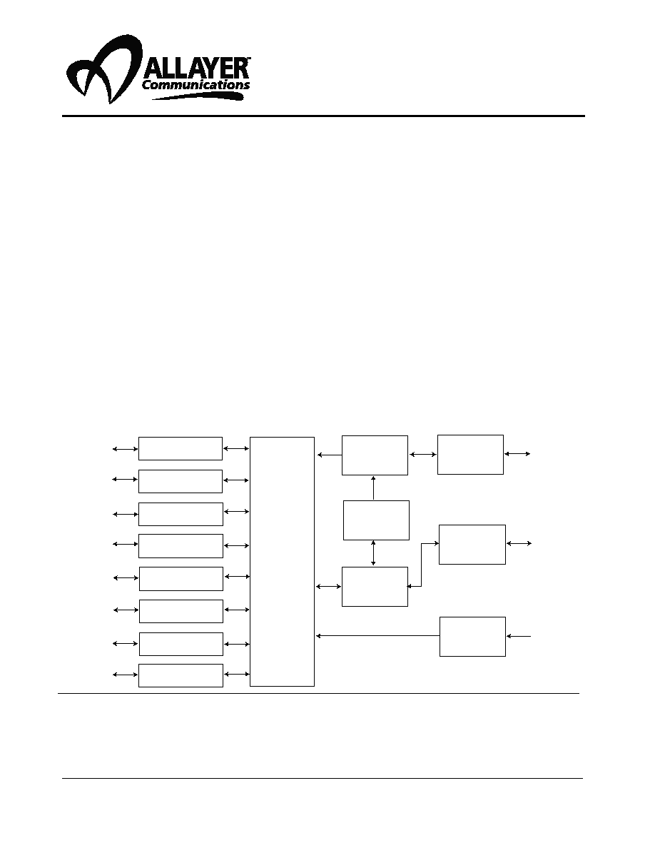
Figure 1
System Block Diagram
�
Supports 8 10/100 Mbit/s Ethernet ports
with RMII interface
�
Capable of trunking up to 800 Mbit/s link
�
Trunk fail-over feature
�
Full- and half-duplex mode operation
�
Speed auto-negotiation through MDIO
�
Built-in storage of 1K MAC addresses
expandable up to 17K
�
Design to utilize low-cost SGRAM
�
Serial EEPROM interface for low-cost
system configuration
�
Automatic source address learning
�
Secure mode traffic filtering
�
Broadcast storm control
�
Port monitoring support
�
IEEE 802.3x flow control for full-duplex
operation
�
Optional backpressure flow control support
for half-duplex operation
�
Supports store-and-forward mode switching
�
VLAN support
�
3.3V operation
�
Packaged in 208-pin PQFP
10/100 MAC
10/100 MAC
10/100 MAC
10/100 MAC
10/100 MAC
10/100 MAC
10/100 MAC
10/100 MAC
High Speed
Switch Fabric
Switch
Controller
Address
Control
Address
Table
Buffer
Manager
Address
Table
Expansion
EEPROM
Interface

AL104 Revision 1.0
9/00
Reference Only / Allayer Communications
2
This document contains proprietary information which shall not be reproduced, transferred
to other documents, or used for any other purpose without the prior written consent of Allayer
Communications.
Disclaimer
Allayer Communications reserves the right to make changes, without notice, in the
product(s) described or information contained herein in order to improve the design and/or
performance. Allayer Communications assumes no responsibility or liability for the use of any
of these products, conveys no license or title under any patent or copyright to these products, and
makes no representations or warranties that these products are free from patent or copyright
infringement unless otherwise specified.
Life Support Applications
Allayer Communications products are not designed for use in life support appliances, systems,
or devices where malfunctions can be reasonably expected to result in personal injury.

Reference Only / Allayer Communications
Table of Contents
1.
AL104 Overview ..................................................................................................... 5
2.
Pin Descriptions....................................................................................................... 7
3.
Functional Description........................................................................................... 16
3.1
Data Reception............................................................................................... 16
3.1.1
Illegal Frame Length .............................................................................. 16
3.1.2
Long Frames .......................................................................................... 16
3.1.3
Frame Filtering....................................................................................... 16
3.2
Frame Forwarding.......................................................................................... 17
3.2.1
Broadcast Storm Control........................................................................ 17
3.2.2
Frame Transmission ............................................................................... 18
3.2.3
Frame Generation................................................................................... 18
3.3
Half Duplex Mode Operation ........................................................................ 18
3.4
Secure Mode Operation ................................................................................. 18
3.5
Address Learning ........................................................................................... 18
3.5.1
Address Aging........................................................................................ 19
3.6
VLAN Support............................................................................................... 19
3.7
Trunking (Port Aggregation).......................................................................... 21
3.7.1
Load Balancing ...................................................................................... 21
3.7.2
Trunk Fail Over...................................................................................... 21
3.7.3
Trunk Port Assignment .......................................................................... 22
3.7.4
Port Based Trunk Load Balancing ......................................................... 22
3.7.5
MAC Based Load Balancing ................................................................. 24
3.8
Flow Control .................................................................................................. 26
3.8.1
Half Duplex Flow Control (Backpressure) ............................................ 26
3.8.2
Full Duplex Flow Control (802.3x) ....................................................... 26
3.9
Queue Management ....................................................................................... 27
3.10
Uplink Port..................................................................................................... 27
3.11
Port Monitoring.............................................................................................. 28
3.12
Reduced Media Independent Interface (RMII).............................................. 28
3.13
Media Independent Interface (MII) ............................................................... 29
3.14
PHY Management.......................................................................................... 29
3.14.1
PHY Management MDIO ...................................................................... 29

AL104 Revision 1.0
9/00
Reference Only / Allayer Communications
4
3.14.2
PHY Management Master Mode ........................................................... 29
3.14.3
PHY Management Slave Mode.............................................................. 30
3.14.4
Non Auto-negotiation Mode .................................................................. 30
3.14.5
Other PHY Options ................................................................................ 30
3.15
EEPROM Interface ........................................................................................ 31
3.15.1
System Initialization .............................................................................. 31
3.15.2
Start and Stop Bit ................................................................................... 31
3.15.3
Write Cycle Timing ............................................................................... 32
3.15.4
Read Cycle Timing ................................................................................ 32
3.15.5
Reprogramming the EEPROM Configuration....................................... 33
3.15.6
EEPROM Map ....................................................................................... 33
3.16
SGRAM Interface .......................................................................................... 37
4.
Register Descriptions ............................................................................................. 37
5.
System Configuration Registers ............................................................................ 40
6.
Timing Requirements............................................................................................. 52
7.
Electrical Specifications ........................................................................................ 61
8.
AL104 Mechanical Data ........................................................................................ 62
9.
Appendix I (VLAN Mapping Work Sheet) ........................................................... 63
10.
Appendix II (Port to Trunk Port Assignment Work Sheet) ................................... 64
11.
Appendix III (Suggested Memory Components)................................................... 65

AL104 Revision 1.0
9/00
Reference Only / Allayer Communications
5
1. AL104 Overview
The AL104 provides eight 10/100 Mbit/s Ethernet ports. Each port supports both 10 and 100
Mbit/s data rate. The operation mode is auto-negotiated by the PHY. All ports are full-duplex
capable. The device also supports VLAN for workgroup and segment switching applications.
The AL104 also supports trunking applications. The chip provides two optional load-balancing
schemes, explicit and dynamic. With trunking, it is possible to group up to four full-duplex links
together to form a single 800 Mbit/s link.
Data received from the MAC interface is stored in the external memory buffer. The AL104 utilizes
cost effective SGRAM to provide 8-Mbit or 16-Mbit of buffer memory.
During transmission, the data is obtained from the buffer memory and routed to the destination
port's output buffer. For half-duplex operation, if a collision occurs the MAC control will back off
and retransmit in accordance to the IEEE 802.3 specification.
The AL104 provides two flow control methods. For half-duplex operations, an optional jamming
based flow control (known as backpressure) is available to prevent loss of data. With this method of
flow control, the switch will generate a jam signal when the receive buffer is full and the sending
station will not start to transmit until the line is clear. In the full-duplex mode, the AL104 utilizes
IEEE 802.3x as the flow control mechanism.
All ports support multiple MAC addresses. The switch chip supports 1K MAC addresses internally
and expandable up to 17K MAC addresses if external SRAM is used. These MAC addresses are
shared among all eight ports.
The initialization and configuration of the switch is programmed by an external EEPROM. Field
reconfiguration can be achieved by using a parallel interface to reprogram the EEPROM.
The AL104 supports port based VLAN. The VLAN register set is used to configure the destination
ports for multicast and broadcast frames.
The device also provides two levels of security for intrusion protection. Security can be
implemented on a per port basis.
The AL104 operates only in the store and forward mode. The entire frame is checked for error and
any frames with errors are automatically filtered and will not be forwarded to the destination port.
The AL104 also features port monitoring and broadcast storm throttling.

AL104 Revision 1.0
9/00
Reference Only / Allayer Communications
6
AL104 Pin Diagram
Figure 2
AL104 Pin Diagram
1
156
157
105
104
Pin 1
ID
5
PBCS#
52
53
110
EEDIO
EECLK
10
PBANC_8
M0CRS
GND
M0COL
M0TXD3
M0TXD2
M0TXD1
M0TXD0
VCC
M0TXEN
M0TXCLK
M0RXER
M0RXCLK
15
20
M0RXDV
M0RXD0
M0RXD1
M0RXD2
M0RXD3
GND
25
ETCLK
ETOE#
ETADSC#
ETADV#
VCC
ETGW#
ETD15
M1CRS
VCC
30
M1TXD1
M1TXD0
M1TXEN
M1RXD0
35
M1RXD1
GND
ETD14
ETD13
ETD12
40
ETD11
ETD10
ETD9
VCC
M2CRS
45
GND
M2TXD1
VCC
M2TXD0
M2TXEN
50
M2RXD0
M2RXD1
55
GND
GND
VCC
VCC
M3CRS
GND
GND
M3TXD1
GND
60
M3TXD0
M3TXEN
M3RXCLK
65
M3RXD0
70
M3RXD1
VCC
VCC
ETD8
ETD7
75
ETD6
ETD5
VCC
ETD4
ETD3
MDC
MDIO
80
RESET#
TESTMODE
ETD2
ETD1
GND
ETD0
85
ETA15
ETA14
ETA13
M4CRS
GND
90
GND
M4TXD1
VCC
M4TXD0
M4TXEN
95
M4RXD0
M4RXD1
GND
GND
VCC
GND
100
M5CRS
VCC
VCC
M5TXD1
M5TXD0
NC
VCCM
M5TXEN
M5RXD0
M5RXD1
GND
GND
ETA12
ETA11
ETA10
115
ETA9
VCC
ETA8
ETA7
ETA6
VCC
120
M6CRS
VCC
VCC
M6TXD1
VCC
125
M6TXD0
M6TXEN
M6RXD0
M6RXD1
GND
GND
ETA5
130
135
ETA4
GND
ETA3
ETA2
ETA1
ETA0
GND
VCC
140
145
M7CRS
VCC
VCC
M7TXD1
VCC
M7TXD0
M7TXEN
M7RXD0
M7RXD1
GND
150
155
GND
VCC
PBCLK
PBD31
PBD30
PBD29
160
165
PBD28
PBD27
PBD26
VCC
PBD25
PBD24
GND
170
PBD15
PBD14
GND
PBD13
PBD12
PBD11
PBD10
PBD9
PBD8
PBD23
PBD22
GND
PBD21
PBD20
PBD19
PBD18
PBD17
PBD16
VCC
175
180
185
190
195
200
205
208
1
PBD7
PBD6
PBD5
PBD4
PBD3
PBD2
PBD1
GND
PBD0
PBA8_9
PBA7
PBA6
PBA5
PBA4
VCC
PBA3
PBA2
PBA1
PBA0
PBA9_10
PBRAS#
VCC
SYSCLK
GND
PBWE#
PBCAS#

AL104 Revision 1.0
9/00
Reference Only / Allayer Communications
7
2. Pin Descriptions
Table 1: MII/RMII Interface Port 0
PIN
NAME
PIN
NUMBER
I/O
DESCRIPTION
M0TXD3
M0TXD2
M0TXD1
M0TXD0
8
9
10
12
O
Transmit Data - NRZ data to be transmitted to transceiver.
Signal M0TXEN, and M0TXD0 through M0TXD3 are clocked
out by the rising edge of M0TXCLK.
For RMII mode, M0TXD3 and M0TXD2 are not used. M0TXD0
and M0TXD1 are clock out by the rising edge of M0RXCLK.
M0TXEN
13
O
Transmit Enable.
Synchronous to the transmit clock.
M0TXCLK
14
I
Transmit Clock Input. Used only for MII mode.
25 MHz for 100 Mbit/s and 2.5 MHz for 10 Mbps.
M0RXD3
M0RXD2
M0RXD1
M0RXD0
22
20
19
18
I
Receive Data - NRZ data from the transceiver.
For MII interface, signals M0RXDV, M0RXER and M0RXD0
through M0RXD3 are sampled by the rising edge of
M0RXCLK.
For RMII mode, M0RXD3 and M0RXD2 are not used. M0RXD0
and M0RXD1 are sampled by the rising edge of M0RXCLK.
M0RXDV
17
I
Receive Data Valid. Used only for MII mode.
M0RXCLK
16
I
Receive Clock. 50 MHz RMII clock for RMII mode.
M0RXER
15
I
Receive Data Error. Used only for MII mode.
M0CRS
5
I
Carrier Sense.
M0COL
7
I
Collision Detect. Used only for MII mode.

AL104 Revision 1.0
9/00
Reference Only / Allayer Communications
8
Table 2: RMII Interface Port 1
PIN
NAME
PIN
NUMBER
I/O
DESCRIPTION
M1TXD1
M1TXD0
32
33
O
Transmit Data - NRZ data to be transmitted to transceiver.
Signal M1TXEN, and M1TXD0 through M1TXD1 are clocked
out by the rising edge of M3RXCLK.
M1TXEN
34
O
Transmit Enable.
Synchronous to the transmit clock.
M1RXD1
M1RXD0
36
35
I
Receive Data - NRZ data from the transceiver.
For RMII interface, signal M1RXD0 through M1RXD3 are
sampled by the rising edge of M3RXCLK.
M1CRS
30
I
Carrier Sense.
Table 3: RMII Interface Port 2
PIN
NAME
PIN
NUMBER
I/O
DESCRIPTION
M2TXD1
M2TXD0
47
49
O
Transmit Data - NRZ data to be transmitted to transceiver.
Signal M2TXEN, and M2TXD0 through M2TXD1 are clocked
out by the rising edge of M3RXCLK.
M2TXEN
50
O
Transmit Enable.
Synchronous to the transmit clock.
M2RXD1
M2RXD0
52
51
I
Receive Data - NRZ data from the transceiver.
For RMII interface, signal M2RXD0 through M2RXD3 are
sampled by the rising edge of M3RXCLK.
M2CRS
45
I
Carrier Sense.
Table 4: RMII Interface Port 3
PIN
NAME
PIN
NUMBER
I/O
DESCRIPTION
M3TXD1
M3TXD0
60
62
O
Transmit Data - NRZ data to be transmitted to transceiver.
Signal M3TXEN, and M3TXD0 through M3TXD1 are clocked
out by the rising edge of M3RXCLK.
M3TXEN
63
O
Transmit Enable.
Synchronous to the transmit clock.
M3RXD1
M3RXD0
66
65
I
Receive Data - NRZ data from the transceiver.
For RMII interface, signal M3RXD0 through M3RXD3 are
sampled by the rising edge of M3RXCLK.

AL104 Revision 1.0
9/00
Reference Only / Allayer Communications
9
M3RXCLK
64
I
50 MHz RMII clock for ports 1 through 7.
M3CRS
57
I
Carrier Sense.
Table 5: RMII Interface Port 4
PIN
NAME
PIN
NUMBER
I/O
DESCRIPTION
M4TXD1
M4TXD0
90
92
O
Transmit Data - NRZ data to be transmitted to transceiver.
Signal M4TXEN, and M4TXD0 through M4TXD1 are clocked
out by the rising edge of M3RXCLK.
M4TXEN
93
O
Transmit Enable.
Synchronous to the transmit clock.
M4RXD1
M4RXD0
95
94
I
Receive Data - NRZ data from the transceiver.
For RMII interface, signal M4RXD0 through M4RXD3 are
sampled by the rising edge of M3RXCLK.
M4CRS
87
I
Carrier Sense.
Table 6: RMII Interface Port 5
PIN
NAME
PIN
NUMBER
I/O
DESCRIPTION
M5TXD1
M5TXD0
103
104
O
Transmit Data - NRZ data to be transmitted to transceiver.
Signal M5TXEN, and M5TXD0 through M5TXD1 are clocked
out by the rising edge of M3RXCLK.
M5TXEN
107
O
Transmit Enable.
Synchronous to the transmit clock.
M5RXD1
M5RXD0
109
108
I
Receive Data - NRZ data from the transceiver.
For RMII interface, signal M5RXD0 through M5RXD3 are
sampled by the rising edge of M3RXCLK.
M5CRS
100
I
Carrier Sense.
Table 4: RMII Interface Port 3 (Continued)

AL104 Revision 1.0
9/00
Reference Only / Allayer Communications
10
Table 7: RMII Interface Port 6
PIN
NAME
PIN
NUMBER
I/O
DESCRIPTION
M6TXD1
M6TXD0
124
126
O
Transmit Data - NRZ data to be transmitted to transceiver.
Signal M6TXEN, and M6TXD0 through M6TXD1 are clocked
out by the rising edge of M3RXCLK.
M6TXEN
127
O
Transmit Enable.
Synchronous to the transmit clock.
M6RXD1
M6RXD0
129
128
I
Receive Data - NRZ data from the transceiver.
For RMII interface, signal M6RXD0 through M6RXD3 are
sampled by the rising edge of M3RXCLK.
M6CRS
121
I
Carrier Sense.
Table 8: RMII Interface Port 7
PIN
NAME
PIN
NUMBER
I/O
DESCRIPTION
M7TXD1
M7TXD0
144
146
O
Transmit Data - NRZ data to be transmitted to transceiver.
Signal M7TXEN, and M7TXD0 through M7TXD1 are clocked
out by the rising edge of M3RXCLK.
M7TXEN
147
O
Transmit Enable.
Synchronous to the transmit clock.
M7RXD1
M7RXD0
149
148
I
Receive Data - NRZ data from the transceiver.
For RMII interface, signal M7RXD0 through M7RXD3 are
sampled by the rising edge of M3RXCLK.
M7CRS
141
I
Carrier Sense.

AL104 Revision 1.0
9/00
Reference Only / Allayer Communications
11
Table 9: SGRAM Interface
PIN NAME
PIN NUMBER
I/O
DESCRIPTION
PBD31
PBD30
PBD29
PBD28
PBD27
PBD26
PBD25
PBD24
PBD23
PBD22
PBD21
PBD20
PBD19
PBD18
PBD17
PBD16
PBD15
PBD14
PBD13
PBD12
PBD11
PBD10
PBD9
PBD8
PBD7
PBD6
PBD5
PBD4
PBD3
PBD2
PBD1
PBD0
154
155
156
157
158
159
161
162
173
174
176
177
178
179
180
181
164
165
167
168
169
170
171
172
183
184
185
186
187
188
189
191
I/O
SGRAM Data Bus.
PBA9_10
202
O
SGRAM Address. For 16 M SGRAM, this pin is PBA10
and for 8-Mbit SGRAM this pin is PBA 9.
PBA8_9
192
O
SGRAM Address. For 16 M SGRAM, this pin is PBA9
and for 8-Mbit SGRAM this pin is PBA 8.
PBANC_8
4
O
SGRAM Address. For 16 M SGRAM, this pin is PBA8
and for 8-Mbit SGRAM this pin is no connect.

AL104 Revision 1.0
9/00
Reference Only / Allayer Communications
12
PBA7
PBA6
PBA5
PBA4
PBA3
PBA2
PBA1
PBA0
193
194
195
196
198
199
200
201
O
SGRAM address line PBA0- PBA7 are sampled during
the ACTIVE command (row address) and READ/
WRITE command (column address with PBA8
defining auto precharge).
PBCS#
1
O
Chip Select. Enables and disables the command
decoder of the SGRAM.
PBRAS#
203
O
SGRAM Row Address Strobe.
PBCAS#
208
O
SGRAM Column Address Strobe.
PBWE#
207
O
Write Enable.
PBCLKI
153
O
System Clock Output to Drive the SGRAM.
Table 10: External Address Table SRAM Interface
PIN NAME
PIN NUMBER
I/O
DESCRIPTION
ETD15
ETD14
ETD13
ETD12
ETD11
ETD10
ETD9
ETD8
ETD7
ETD6
ETD5
ETD4
ETD3
ETD2
ETD1
ETD0
29
38
39
40
41
42
43
69
70
71
72
74
75
80
81
83
I/O
SRAM Data Bus.
Table 9: SGRAM Interface (Continued)

AL104 Revision 1.0
9/00
Reference Only / Allayer Communications
13
ETA15
ETA14
ETA13
ETA12
ETA11
ETA10
ETA9
ETA8
ETA7
ETA6
ETA5
ETA4
ETA3
ETA2
ETA1
ETA0
84
85
86
112
113
114
115
117
118
119
132
133
135
136
137
138
O
SRAM Address Line.
ETADSC#
25
O
Synchronous Address Status Controller.
ETADV#
26
O
Synchronous Address Advance. Used to advance the
SRAM's internal burst counter.
ETGW#
28
O
Global Write. Enables a full 32-bit write.
ETOE#
24
O
Output Enable. Active low. This enables data I/O
output driver.
ETCLK
23
O
System Clock Output.
Table 11: EEPROM Interface
PIN NAME
PIN NUMBER
I/O
DESCRIPTION
EEDIO
2
I/O
EEPROM Serial Data Input and
Output.
EECLK
3
O
EEPROM Serial Clock.
Table 12: PHY Management Interface
PIN NAME
PIN NUMBER
I/O
DESCRIPTION
MDC
76
O
PHY Management Clock.
MDIO
77
I/O
PHY Management Data Input and
Output.
Table 10: External Address Table SRAM Interface (Continued)

AL104 Revision 1.0
9/00
Reference Only / Allayer Communications
14
Table 13: Miscellaneous Pins
PIN NAME
PIN NUMBER
I/O
DESCRIPTION
RESET#
78
I
Reset
TESTMODE
79
I
Test Mode Pin. This pin should be
grounded for normal operation.
SYSCLK
205
I
80 MHz System clock.
NC
105
--
No Connect. Must be left
unconnected.
Table 14: Power Interface
PIN NAME
PIN NUMBER
DESCRIPTION
GND
6, 21, 37, 46, 53, 54, 58, 59, 61, 82,
88, 89, 96, 97, 99, 110, 111, 130,
131, 134, 139, 150, 151, 163, 166,
175, 190, 206
Ground
Vcc (3.3V)
11, 27, 31, 44, 48, 55, 56, 67, 68, 73,
91, 98, 101, 102, 116, 120, 122, 123,
125, 140, 142, 143, 145, 152, 160,
182, 197, 204
3.3V Supply Voltage.
VccM
106
Supply Voltage for MII/RMII Interface.
VccM = 5V (5V MII/RMII interface)
VccM = 3.3V (3.3V MII/RMII interface)

AL104 Revision 1.0
9/00
Reference Only / Allayer Communications
15
Figure 3
AL104 Interface Block Diagram
High Speed
Switch Fabric
Switch
Controller
Address
Control
Address
Table
EEPROM
Interface
Buffer
Manager
Management
Information
PHY
Management
MDIO
MDC
EEDIO
EECLK
RESET
10/100 MAC
10/100 MAC
10/100 MAC
10/100 MAC
10/100 MAC
10/100 MAC
10/100 MAC
10/100 MAC
PBD[n]
PBA[n]
PBBA
PBCS
PBRAS
PBCAS
PBWE
PBDSF
PBDQM
PBCLK
MXTXD3
MXTXD2
MXTXD1
MXTXD0
MXTXEN
MXTXCLK
MXRXD3
MXRXD2
MXRXD1
MXRXD0
MXRXDV
MXRXCLK
MXCRS
MXCOL
MXRXER
32
9
ETADSC
ETADV
ETAGW
ETOE
ETCLK
ETA[n]
ETD[n]
SRAM
Interface

AL104 Revision 1.0
9/00
Reference Only / Allayer Communications
16
3. Functional Description
3.1 Data Reception
The data reception port will go into the receive-state when CRS in the RMII interface is asserted.
The RMII (Reduced Media Independent Interface) presents the received data in two-bit (di-bit) that
are synchronous to the RMII reference clock (50 MHz). The AL104 will then attempt to detect the
occurrence of the SFD (Start Frame Delimiter) pattern "10101011." All preamble data prior to SFD
are discarded. Once SFD is detected from the RMII interface, the frame data is forwarded and
stored in the buffer of the switch.
3.1.1 Illegal Frame Length
During the receiving process, the AL104 MAC will monitor the length of the received frame. Legal
Ethernet frames should have a length of no less than 64 bytes and no more than 1536 bytes. Any
frames with illegal frame length are discarded.
3.1.2 Long Frames
The AL104 can handle frame size up to 1536 bytes. All frames longer than 1536 bytes will be
discarded. If the port continues to receive data after the 1536
th
byte, the port's data will be filtered.
If the port is in half-duplex mode, the port will no longer be able to transmit or receive data during
the long frame reception.
3.1.3 Frame Filtering
The AL104 will make filtering and forwarding decisions for each frame received based on its frame
routing table, VLAN Mapping, port state, and the system configuration.
Under the following conditions, received frames are filtered:
�
The AL104 will check all received frames for errors such as symbol error, FCS
error, short event, runt, long event, etc. Frames with any kind of error will not be
forwarded to their destination port.
�
Any frame heading to its own source port will be filtered.
�
Frames heading to a disabled receiving port will be filtered.
�
If the frame buffer is full, the incoming frame will be discarded. It is
recommended that the flow control be used to prevent any loss of data. If the flow
control option is enabled, this event will not occur. The remote station will
transmit frame when the frame buffer becomes available.
�
If the frame has any security violation and the security option is enabled at the
receiving port.

AL104 Revision 1.0
9/00
Reference Only / Allayer Communications
17
3.2 Frame Forwarding
After a frame is received, both source address (SA) and destination address (DA) are retrieved. The
SA is used to update the port's address table and the DA is used to determine the frames destination
port. The Address Lookup Engine will attempt to match the destination address with the addresses
stored in the address table. If there is a match found, a link between the source port and the
destination port is then established.
If the first bit of the destination address is "0," the frame is regarded as an unicast frame. The
destination address is passed to the Address Lookup Engine, which returns a matched destination
port number to identify which port the frame should be forwarded to. If the destination port is
within the same VLAN of the receiving port, the frame will be forwarded. If the destination port
does not belong to the VLANs specified at the receiving ports, the frame will be discarded. The
event will be recorded as a VLAN boundary violation.
There are two ways that the AL104 handles frames with unknown destinations. The forwarding
decision is controlled by the Flood Control option (System Configuration Register 00). If Flood
Control is disabled, the frame will be forwarded to all ports (except the receiving port) within the
same VLANs of the receiving port. If the Flood Control option is enabled, the AL104 will forward
the frame only to the uplink port specified at the receiving port.
Note:
The AL104 defines a port as either a single port or a trunk.
If the port monitoring function is enabled, the frame forwarding decision is also subject to the port
monitoring configurations.
If the first bit of the destination address is a "1," the frame will be handled as a multicast or
broadcast frame. The AL104 does not differentiate multicast frames from broadcast frames except
for the reserved bridge management group address, as specified in table 3.5 of IEEE 802.1d
standard. The destination ports of the broadcast frame are all ports within the same VLAN except
the source port itself.
3.2.1 Broadcast Storm Control
One of the unique features provided by the AL104 is Broadcast Storm Control. This option allows
the user to limit the number of broadcast frames into the switch. This option can be implemented on
a per port basis. A threshold number of broadcast frames can be programmed in System Register II
(register 01).
When Storm Control is enabled and the number of cumulated non-unicast frames is over the
programmed threshold, the broadcast frame is discarded.
If Storm Control is disabled, or the number of non-unicast frames received is not over the
programmed threshold, the AL104 will forward the frame to all ports (except the receiving port)
specified within the VLANs at the receiving port.
If Broadcast-Storm-drop (BConly_SC) is enabled in System Register III (register 02), the AL104
will only drop broadcast frames but not the multicast frames.

AL104 Revision 1.0
9/00
Reference Only / Allayer Communications
18
3.2.2 Frame Transmission
The AL104 transmits all frames in accordance to IEEE 802.3 standard. The AL104 will send the
frames with a guaranteed minimum IPG (Inter Packet/Frame Gap) of 96BT even if the received
frames have an IPG less than the minimum requirement. The AL104 also supports transmission of
frames with an IPG of 64BT (optional). This option can be selected in System Register III, Bit 8,
Register 02.
3.2.3 Frame Generation
During a transmit process the frame data is read from the memory buffer and forwarded to the
destination port's PHY device in di-bits. Seven bytes of preamble signal (10101010) will be
generated first before the SFD (10101011). Frame data is sent after the SFD along with four-bytes
of FCS at the end.
3.3 Half Duplex Mode Operation
For half-duplex operation, the MAC logic will abort the transmit-process if collision is detected.
Re-transmission of the frame is scheduled in accordance to IEEE 802.3's truncated binary
exponential back off algorithm. If the transmit process has encountered 16 consecutive collisions,
an excessive collision error is reported and AL104 will not try to re-transmit the frame unless the
retry-on-excessive-collision (REC) option in System Register III (register 02) is enabled. When
REC is enabled, the number of collisions are reset to zero and transmission is started as soon as 96
bit time of inter-packet gap is passed after the last collision. If a collision is detected after 512 BT of
the transmission, a late collision error will be reported but the frame will still be retransmitted after
proper back off time.
The AL104 also provides an option for an aggressive back off in the System Configuration Register
II (SuperMAC). This option allows the MAC to back off only three slots. This will create a more
aggressive channel capture behavior than the standard IEEE back off algorithm.
3.4 Secure Mode Operation
The AL104 provides security support on a per port basis. Whenever the secure mode is enabled, the
port will stop learning new addresses. The address table of each port will remain unchanged. In this
mode of operation, the address lookup table will freeze and no additional new address will be
learned.
The AL104 provides two levels of security protection. The most severe intrusion protection is
disabling a port if intrusion is experienced. The security management (SecMgmt bit in register 01)
will disable a port if a frame with unlearned source address (SA) is received from a secured port
(security violation). An alternative is to enable security at the local port level without the security
management. When the AL104 is configured this way, the device will only discard frames that have
security violations, which prevents intruders from accessing the network.
3.5 Address Learning
The Table Lookup Engine provides the switching information required to route data frames. The
address look up table is set-up through auto address learning (dynamic) or manual entry (static).
The static addresses are assigned to the address table by the EEPROM. All static address entries
will not be aged or updated by the AL104.

AL104 Revision 1.0
9/00
Reference Only / Allayer Communications
19
After a frame is received by the AL104, the embedded (SA) and destination address (DA) are
retrieved. The source address retrieved from the received frame is automatically stored in a SA
buffer. The AL104 will then check for error and security violations, and perform a SA search. If
there is no error or security violation, the AL104 will store the source address in the address lookup
table. If the SA has been previously stored in another port's SA table, the AL104 will delete the SA
from the previously stored location.
The Individual MAC Address is a 48-bit unique MAC address to be programmed or learned. Bit 0
of a SA will be masked, i.e. no multicast SA.
The AL104 provides an on-chip 1K MAC Address-to-PortID/TrunkID table for the frame
destination look-up operations. This table can be expanded up to 17K entries if an external SRAM
is used.
The AL104 address table contains both static addresses input by the EEPROM and dynamically
learned address. It learns the individual MAC addresses from frame received with no errors from
the local ports.
For received frames that contain a source address learned in another port's address table, that hasn't
been aged out, perform the following based on the switches; if the security option is selected for the
port, the AL104 considers this a security violation; if port is a non-protected port, the AL104 will
delete the SA from the previous port's address table and update it to the current port's address table.
However, if the SA is a static address entry, the address will not be updated.
3.5.1 Address Aging
A port's MAC address register is cleared on power-up, or hardware reset. If the SA aging option is
enabled, the dynamically learned SA will be cleared if it is not refreshed within the programmed
time.
3.6 VLAN Support
Each port of the AL104 can be assigned to one or multiple VLANs. Frames from the source port
will only be forwarded to destination ports within the same VLAN domain. A broadcast/multicast
frame will be forwarded to all ports within the VLAN(s) except the source port itself. A unicast
frame will be forwarded to the destination port only if the destination port is in the same VLAN as
the source port. Otherwise, the frame will be treated as a frame with unknown DA. If the
destination port belongs to the another VLAN, the frame will be discarded and the event will be
recorded as a VLAN boundary violation.
Each port can be assigned with a dedicated uplink port. Unicast frames with unknown destination
addresses will be forwarded to the uplink port of the source port. An uplink port can be either a
single port or a trunk.
The AL104 provides one VLAN register per ports (register 1E to 2C) for mapping to eight-ports
(eight-bits). Each register contains an 8-bit bit-map to indicate the VLAN group for the port.
The VLAN registers hold a broadcast destination mask for each source port. The value "1" will
indicate the broadcast frames will be routed from the source port to the specified port. Note that the
source port bit must be set to "0" within the source port VLAN, because broadcast frames are not
routed to the source port.
For setting up VLAN for trunking, please see the following section on trunking for detail.

AL104 Revision 1.0
9/00
Reference Only / Allayer Communications
20
VLAN Set Up Example
A VLAN set up worksheet is provided in Appendix 1. You can complete the VLAN map easily by
simply marking the ports you wish to send broadcast frame to.
For example, let's assume we want to set up two VLAN groups in an 8-port switch;
Group 1 consists of: 0, 1, 2, 5, and 6.
Group 2 consists of: 2, 3, 4, and 7.
The completed VLAN bit maps are shown in Table 15.
Table 15: VLAN Map for an 8 Port Switch
PORT
BIT
P
O
R
T
0/R
E
G
.
1E
PO
R
T
1/RE
G
.
20
PO
R
T
2/RE
G
.
22
POR
T
3
/
R
E
G.
24
PO
R
T
4/RE
G
.
26
PO
R
T
5/RE
G
.
28
PO
R
T
6/RE
G
.
2A
PO
R
T
7/RE
G
.
2C
7
7
0
0
1
1
1
0
0
0
6
6
1
1
1
0
0
1
0
0
5
5
1
1
1
0
0
0
1
0
4
4
0
0
1
1
0
0
0
1
3
3
0
0
1
0
1
0
0
1
2
2
1
1
0
1
1
1
1
1
1
1
1
0
1
0
0
1
1
0
0
0
0
1
1
0
0
1
1
0

AL104 Revision 1.0
9/00
Reference Only / Allayer Communications
21
3.7 Trunking (Port Aggregation)
The AL104 supports trunking/port aggregation.
Port aggregation and trunking is essentially a
method to treat multiple physical links as a single logical link. The benefit of trunking is the ability
to group multiple lower speed links into one higher speed link. For example, four full-duplex 100
Mbps links can be used as one single 800-Mbps link. This is very useful for switch to switch,
switch to server, and switch to router applications.
The AL104 considers a trunk as a single port entity regardless of the trunk composition. Two to
four ports can be grouped together as a single trunk link. The grouping of the ports in the trunk
must be from the top four ports or the bottom four ports of the device, i.e. port 0 to 3 or port 4 to 7.
In a multiple link trunk, the links within the trunk should have a balanced amount of traffic in order
to achieve maximum efficiency. One of the requirements for transmission is that the frames being
transmitted must be in order. Therefore, some sort of load balancing among the links of the trunk
must be deployed. The AL104 offers two methods of load balancing which can be selected in the
System Configuration Register I (register 00).
3.7.1 Load Balancing
The two load-balancing methods that AL104 uses to support trunking are port based and MAC
address based. Port based load balancing method is an explicit port assignment scheme. It requires
each individual port to be assigned to a specific link (trunk port) in the trunk. If the port is not
assigned, the frame might be routed to the trunk randomly which may cause the frames to go out of
order. The port based load balancing trunk can be assigned as a 2-, 3-, or 4-port trunk.
During transmission of the frame, it will be routed from the source port to the assigned trunk port.
When a frame is received from any one of the trunk ports, it will be routed to the destination port
within the VLAN. In essence, the AL104 treats a trunk as any single port within the same VLAN. If
the ports traffic is evenly distributed among all the trunk ports, load balancing is achieved and the
aggregate bandwidth of the trunk can be as high as 800 Mbit/s (full-duplex).
The alternative is the MAC address based load balancing. When the AL104 receives a frame with a
trunk destination, it will automatically forward the frame to a port in the trunk based on the source,
destination, or the combination of the source and destination MAC address. The MAC address load
balancing decision is based on a proprietary algorithm. The MAC address based load-balancing
trunk also can be assigned as a 2-, 3-, or 4-port trunk.
3.7.2 Trunk Fail Over
If a link is lost in one of the trunk ports, frame loss will occur. The trunk fail over feature in the
AL104 can prevent frame loss caused by link failure in a trunk port. When the trunk fail over option
is enabled in register 2D bit 9 (L2Fail), the AL104 will automatically shift the load from the port
with the lost link to the next available port. This option is available for MAC address based loading
trunk only. Once the port with a lost link recovers and links up, the AL104 will return to the original
trunk setting.

AL104 Revision 1.0
9/00
Reference Only / Allayer Communications
22
3.7.3 Trunk Port Assignment
The maximum number of trunks for the AL104 is two. The Port Configuration I registers provide
the ability to designate a port to be a member of a trunk. The trunk can consist of up to four trunk
ports. A trunk group must consist of either the top four ports or the bottom four ports, for example a
trunk can consist of port 0 through port 3 or port 4 through port 7. Each trunk port's number is in
sequence of 00, 01, 10, and 11 corresponding to the order of port of the devices. For example, port
1 and 5 are 01.
Figure 4
Trunk Port Numbering
3.7.4 Port Based Trunk Load Balancing
For port-based load balancing, a trunk port must be assigned to each port for all defined trunks. The
port assignment is done by programming Port to Trunk Port Registers (2E to 35). It is
recommended that ports be evenly distributed among all trunk ports to prevent overloading any
single trunk port.
Port Based Load Balancing Set Up Example:
Register bits are reference by X.Y, where "X" is the register number and "Y" is the bit number. A
port assignment worksheet is provided in Appendix I for port to trunk port and VLAN assignment.
The example is designing an 8-port switch with a 3-port based loading trunk. The desired trunk
ports are 5, 6, and 7. We want to assign port 0 to trunk port 5, port 1 and 3 to trunk port 6, and port
2 and 4 to trunk port 7.
1.
The Port Configuration I register bits 17.9, 19.9, and 1B.9 are set to 1. This
assigns ports 5, 6, and 7 as a trunk port.
2.
Assign port 0 to trunk port 5, port 1 and 3 to trunk port 6, and port 2 and 4 to trunk
port 7. Therefore, set port to trunk port register bits as follows:
2E.2= 0, 2E.3 =1
2F.2= 1, 2F.3 =0
30.2= 1, 30.3 =1
31.2= 1, 31.3 =0
1
2
3
0
4
5
6
7
Ports
AL104
Trunk Port 0
Trunk Port 1

AL104 Revision 1.0
9/00
Reference Only / Allayer Communications
23
32.2= 1, 32.3 =1
3.
Trunk ports should be assigned with their own port number in the port to trunk
Port register. The port to trunk-port bits are as follows:
33.2= 0, 33.3 =1
34.2= 1. 34.3 =0
35.2= 1, 35.3 =1
Note:
Set the remaining bits to all zeros in port to trunk port registers.
4.
Assigning VLAN. The VLAN map should be assigned as shown.
All bits are set to "1" while the bits 1E.6 and 1E.7 are set to "0" because port 0 is assigned to port 5.
All the other ports are set up similarly. Bits 15 through 8 are reserved and should be set to `0' for all
VLAN mapping registers.
Table 16: VLAN Mapping for Port Based Load Balancing Trunk
PORT
BIT
PO
R
T
0/
R
E
G
.
1E
P
O
R
T
1/RE
G
.
20
P
O
R
T
2/RE
G
.
22
P
O
R
T
3/RE
G
.
24
P
O
R
T
4/RE
G
.
26
P
O
R
T
5/RE
G
.
28
PO
R
T
6
/
R
E
G.
2A
PO
R
T
7
/
R
E
G.
2C
7
7
0
0
1
0
1
0
0
0
6
6
0
1
0
1
0
0
0
0
5
5
1
0
0
0
0
0
0
0
4
4
1
1
1
1
0
1
1
1
3
3
1
1
1
0
1
1
1
1
2
2
1
1
0
1
1
1
1
1
1
1
1
0
1
1
1
1
1
1
0
0
0
1
1
1
1
1
1
1

AL104 Revision 1.0
9/00
Reference Only / Allayer Communications
24
3.7.5 MAC Based Load Balancing
For MAC address based load balancing, there is no need to assign a port to a trunk port. The AL104
dynamically assigns MAC addresses to the trunk port. MAC address based trunks can consist of
two, three, or four trunk ports. The bits are chosen for their randomness. The statistically random
bits will ensure good load balancing among all trunk-ports.
The following is a procedure to set up the MAC based load trunk.
1.
Select MAC address load trunking by setting bit 00.3 to "1."
2.
Select the trunk ports using Port Configuration Register I, Bit 9.
3.
Assign the ports and the trunk port to the same VLAN using register 1E to 2C.
4.
When the number of trunk ports is four, the following steps are not required. If the
number of trunk ports are two or three, set register bit 2D.8 (L2MAP) to "1."
5.
Set the Trunk Map 1 or Trunk Map 0 in Register Bits 7 through 0. These bits
indicate the mapping of trunk ports. For example, if ports 0 and 1 are used as trunk
ports, then set the bits 2D.0 and 2D.1 to "1." If ports 5 and 7 are used as trunk
ports, set bits 2D.5 and 2D.7. The trunk port mapping and the trunk member bits
set in Port Configuration I register must match.
6.
Finally, select the algorithm for MAC based loading. Set register 2D.10 to "1" for
source address only, and "0" for the combination of source and destination
addresses.
The port VLAN grouping should include all the trunk ports. Since the AL104 will assign the port
by MAC addresses, frames from any single port may be routed to any trunk ports.

AL104 Revision 1.0
9/00
Reference Only / Allayer Communications
25
MAC Based Load Balancing Example
The desired trunk port is 4, 5, 6, and 7. Therefore, the port configuration register bits 15.9, 17.9,
19.9, and 1B.9 are set to "1." Select MAC address loading by setting bit 00.3 to "1."
Note:
All bits are set to "1" except the ports themselves.
Table 17: VLAN Mapping for MAC Based Loading Trunk
PORT
BIT
PO
R
T
0
/
R
E
G.
1D
PO
R
T
1/RE
G
.
1F
P
O
R
T
2/RE
G
.
21
P
O
R
T
3/RE
G
.
23
P
O
R
T
4/RE
G
.
25
P
O
R
T
5/RE
G
.
27
P
O
R
T
6/RE
G
.
29
PO
R
T
7
/
R
E
G.
2B
7
7
1
1
1
1
0
0
0
0
6
6
1
1
1
1
0
0
0
0
5
5
1
1
1
1
0
0
0
0
4
4
1
1
1
1
0
0
0
0
3
3
1
1
1
0
1
1
1
1
2
2
1
1
0
1
1
1
1
1
1
1
1
0
1
1
1
1
1
1
0
0
0
1
1
1
1
1
1
1

AL104 Revision 1.0
9/00
Reference Only / Allayer Communications
26
3.8 Flow Control
The AL104 can operate at two different modes, half- and full-duplex. Each port can operate at
either full- or half-duplex and be configured to have flow control enabled or no flow control
independently on a per port basis.
3.8.1 Half Duplex Flow Control (Backpressure)
If the half-duplex flow control option is selected, back-pressure will be used for flow control.
Whenever the receive frame buffer of a port is full, the MAC of the port will start sending a JAM
signal through the port. The remote station after sensing the JAM signal will defer transmission.
Backpressure flow control is applied to ensure that there is no dropped frame. The AL104 supports
two types of backpressure, collision based and carrier based.
Carrier based backpressure is generated by the AL104, when the switch port's frame buffer is full.
The AL104 will cease to jam the line when the port has buffer space available for frame reception.
The IPG of the jamming signal can be selected from 48BT, 56BT, 65BT, 72BT, and 96BT. This can
be selected in register 02 bits 3 and 2. The BpIPGSelEn bit must be set to 1 to select backpressure
IPG less than 96BT.
The carrier based backpressure has several advantages over collision based backpressure such as
collision based backpressure can cause a late collision. After 16 consecutive collisions, the MAC
could drop frames. The AL104 has an option not to drop frame after 16 collisions. However, the
end terminal may still drop frames. Therefore, we recommend the use of carrier based backpressure
as the preferred method for half-duplex flow control. In this mode of operation, we also recommend
that the IPG of the JAM signal should be set at less than 96BT. This is because if the IPG is at
96BT, the far end terminal might still be able to transmit the frame and cause a collision. The
excessive collision could cause frames to be dropped.
Collision based backpressure is generated by the AL104, only when the switch port receives a
frame. The AL104 will cease to jam the line, when the line is idle. The AL104 supports collision-
based backpressure for customers that prefer collision-based backpressure.
3.8.2 Full Duplex Flow Control (802.3x)
In the full-duplex mode, the AL104 will transmit and receive the frame in accordance to 802.3x.
Note that the transmission channel and the receiving channel operate independently.
In the incoming direction, whenever the receive frame buffer of a port is full, the MAC of the port
will send out a PAUSE frame with its delay value set to maximum. The PAUSE frame will deter any
incoming frame from flowing into the port. After the receive frame buffer is reduced below the
backpressure watermark level (register 04 bit 11, 10), the MAC of the port will then send out a
PAUSE frame with the delay value set to zero to resume receiving the incoming frame flow.
In the outgoing direction, whenever a incoming PAUSE frame with a non-zero delay value is
received through a port, the MAC of the port will stop the next frame transmission after the ongoing
frame transmission is finished. It will start its pause timer and resume frame transmission either
after the pause timer expired or when a PAUSE frame with a zero delay value is received.
When the 802.3x flow control option is elected, the device will program the appropriate bit in the
auto-negotiation capability field. When the AL104 is used in the full-duplex mode, it is
recommended that flow control should be turned on which prevents the buffer from overflow and

AL104 Revision 1.0
9/00
Reference Only / Allayer Communications
27
loss of frames. If the connected device has no 802.3x capability, then the recommended link setting
is half-duplex.
3.9 Queue Management
The AL104 ports have an advanced queue management algorithm for optimal switching
performance. All frames received by AL104 are stored into the shared memory. If the frame is
unicast type, the location of the frame in the buffer is then passed to the destination output queue
manager. It is up to the Destination Output Queue Manger to extract the frame from the buffer and
transmit. If the output queue manager receives more frames than it can send out, it simply stores the
locations of the frames and transmits them after transmitting the current frame.
There are two ways to manage the output queues. One method is that all eight output queues will
share the frame buffer to the shared memory limit, without limit to each individual queue. When
this method is chosen by setting bit 00.15 to "0," shared buffer memory is allocated to the incoming
frame from any port as long as free buffer is available. When extreme cases of congestion are
experienced, such as traffic merging into a single port or speed mismatch for a long period of time,
a single output queue may occupy the entire shared buffer causing other ports to drop frames. In
this case, the flow control option is recommended so when the frame buffer is full, incoming frames
will be backpressured. To prevent buffer starvation, half of the memory is reserved and allocated to
each port while the other half is shared.
The other option is to limit the number of frames that each output queue can store. This option is
selected by setting bit 00.15 to "1." An output queue watermark can be set in System Configuration
Register I (register 00 bits [7:6]) to keep the balance between utilization and fairness of buffer
sharing. This method prevents other ports from suffering performance reduction due to a single port
experiencing an extreme congestion. If severe congestion is experienced in a single port, only that
port will suffer from frame loss because the buffer is limited to its dedicated portion. Other ports
will not experience any frame loss due to congestion problem in other ports since all other ports
retain their own allocated buffer space.
When an output queue or multicast queue experiences a buffer full condition, the AL104 will
backpressure the incoming frames if flow control is enabled. A watermark for buffer full condition
can be selected in register 04.
3.10 Uplink Port
The uplink port provides a means to connect the switch with a repeater hub, a workgroup switch, a
router, or any type of interconnecting device compliance with IEEE 802.3 standards.
If flood control is enabled, the AL104 will send all frames with unmatched DA and multicast/
broadcast frames to the uplink port. It is very important that each port is assigned to an uplink port
via the Port Configuration Register (0D to1C), or data frames might be lost. The uplink port should
be configured to be within the same VLAN of the source port. If the uplink port is not a member of
the VLANs, the broadcast or multicast frames will not be forwarded to its designated uplink port.
Multiple VLANs can share the same uplink port.
The AL104 will direct the following frames to the uplink port:
�
Frames with a unicast destination address that doesn't match with any MAC
address stored in the switch; and

AL104 Revision 1.0
9/00
Reference Only / Allayer Communications
28
�
Frames with a broadcast/multicast destination address if the uplink port is in the
same VLAN.
Note:
When configuring an uplink port, the uplink port should designate itself as the
uplink port.
3.11 Port Monitoring
The AL104 supports port monitoring. This feature provides complete network monitoring
capability at 100 Mbit/s. A copy of egress (TX) data and ingress (RX) data of the monitored port is
sent to their respective snooping ports.
The monitored port is selected by register 06. The AL104 allows transmit and receive data to be
monitored by different snooping ports. The snooping ports are also selected by register 06.
3.12 Reduced Media Independent Interface (RMII)
The RMII has only six signal pins and a clock pin. The signal pins are TXD0, TXD1, RXD0,
RXD1, TXEN and CRS. The M3RXCLK pin is the common reference clock at 50 MHz for ports 1
through 7. Port 0 requires a separate clock through M0RXCLK if port 0 is in RMII mode.
For frame reception, the received data (RXD[1:0]) are sampled by the rising edge of reference
clock. Assertion of the CRS signal indicates the receive channel is active. The di-bit RXD[1:0] is
nominally "00" until the PHY detects a valid SFD and send preamble as "01." Valid data will
follow after SFD.
For frame transmission, the transmit data enable (TX_EN) signal is asserted when the first
preamble nibble is sent on the transmit data (TXD) lines. The transmit data is clocked out by the
rising edge of the reference clock.
Prior to any data transaction, AL104 will output 2-bits of "0" as preamble signal and then after the
preamble, a "11" signal is used to indicate the start of the frame.

AL104 Revision 1.0
9/00
Reference Only / Allayer Communications
29
3.13 Media Independent Interface (MII)
Port 0 of the AL104 has an option for MII mode. For frame reception, the received data (RXD[3:0])
is sampled at the rising edge of the receive clock (RX_CLK). Assertion of the receive data valid
(RX_DV) signal will cause the MAC to look for start of SFD. For transmission, the transmit data
enable (TX_EN) signal is asserted when the first preamble nibble is sent on the transmit data
(TXD[3:0]) lines. The transmit data is clocked out by the rising edge of the transmit clock
(TX_CLK).
Prior to any transaction, the AL104 will output 32-bits of "1" as a preamble signal and then after
the preamble, a "01" signal is used to indicate the start of the frame.
3.14 PHY Management
The AL104 supports transceiver management through the serial MDIO and MDC signal lines. The
device provides two modes of management, master and slave mode. In the master mode of
operation, the AL104 controls the operation modes of the link but in the slave mode the PHY
controls the operating mode.
3.14.1 PHY Management MDIO
For a write operation, the device will send a "01" to signal a write operation. Following the "01"
write signal there will be the 5-bit ID address of the PHY device and the 5-bit register address. A
"10" turn around signal is then used to avoid contention during a read transaction. After the turn
around, the 16-bit of data will be written into the register and then after the completion of the write
transaction, the line will be put in a high impedance state.
For a read operation, the AL104 will output a "0" to indicate a read operation after the start of the
frame indicator. Following the "10" read signal will be the 5-bit ID address of the PHY device and
the 5-bit register address. Then, the AL104 will cease driving the MDIO line, and wait for one bit
time. During this time, the MDIO should be in a high impedance state. The device will then
synchronize with the next bit of "0" driven by the PHY device, and continue to read 16-bit of data
from the register. The detail timing requirements on PHY management signals are described in the
section "Timing Requirement."
3.14.2 PHY Management Master Mode
In the master mode, the AL104 will continuously poll the status of the PHY devices through the
serial management interface. The device will also configure the PHY capability fields to ensure
proper operation of the link.
The configuration of the link is automatic. The link capability is programmed by the AL104
through the port configuration register. The AL104 reads from the standard IEEE PHY registers to
determine the auto-negotiated operating speed and mode. If there is a need to manually set the
operation mode because of flow control and cabling issues the AL104 can set the port operation
mode through the MDIO interface (see EEPROM section for programming the AL104).

AL104 Revision 1.0
9/00
Reference Only / Allayer Communications
30
3.14.3 PHY Management Slave Mode
In the slave mode, the PHY controls the programming of the operating mode. The AL104 will
continuously poll the status of the PHY devices through the serial management interface to
determine the operation mode of the link.
This mode of PHY management is very useful for unmanaged switches. The operating mode of the
link can be changed by programming the mode pin of the PHY through a jumper.
The AL104 also supports 100Base-TX transceivers without a MDIO interface or MII to MII
interface. Note that this is available for port 0 only. When MDIO is disabled, the AL104 will
operate in the operation mode specified in the Port Configuration Register (register 0D to 1C).
3.14.4 Non Auto-negotiation Mode
The AL104 can also turn off the auto-negotiation capability of the PHY. When auto-negotiation is
turned off, the AL104 is in the slave mode and the transceiver will determine the link's operating
mode.
3.14.5 Other PHY Options
Some Legacy Fast Ethernet devices and other low cost devices have no auto-negotiation capability.
In those cases when the transceiver will not be able to perform auto-negotiation, the switch
transceiver will typically do a parallel detection and update the information in the transceiver's
register. Unfortunately, such register addresses are vendor specific. The AL104 provides a register
(register 05) to specify the register address of the PHY for the AL104 to read. The AL104 will read
from that register and configure the port operation accordingly.
Register 05 also provides some additional flexibility's for some of the PHYs in the market. In
general, the system designer should set the ID of the PHY devices as 0 for port 0, 1 for port 1, and 7
for port 7. Certain PHY's utilize PHY address 00000 as a broadcast address. Bit 1 of the register 05
allows the AL104 to start with PHY address 01000. This provision allows the engineers to work
around the PHY's that have problems handling address 00000.
Quad PHYs may have 2-port ordering in the chip pinout, both clockwise and counter clockwise.
Register 05 bit 2, programs the AL104 port order to go in either direction. This provision enables
engineers to easily implement designs with any PHY.
There is also a slow MDIO clock (17 KHz) available for PHY that is not capable of handling a high
speed MDIO clock.
If for some reason, the transceiver is connected to a device and that device fails to auto negotiate,
the AL104 will default the data rate and duplex mode to the default setting in the port configuration
register.
AL104 Revision 1.0
9/00
Reference Only / Allayer Communications
31
3.15 EEPROM Interface
The AL104 provides three functions with the EEPROM interface: system initialization, obtaining
system status, and reconfiguring the system in real time. The AL104 uses the 24C02 serial
EEPROM device (2048 bits organized as 256 bits x 8).
3.15.1 System Initialization
The EEPROM interface is provided so that the manufacturer can provide a pre-configured system
to their customers which allows customers to change or reconfigure their system and retain their
preferences. The EEPROM contains configuration and initialization information, which will be
accessed at power up or reset.
If the reset pin is held low, the AL104's EEPROM interface will go into a high impedance state.
This feature is very useful for reprogramming the EEPROM during installation or reconfiguration.
The EEPROM can be reprogrammed by an external parallel port. For reprogramming using a
parallel port, a signal is used to hold the RESET pin low. The EEPROM interface will then be in the
high-impedance state. An external device can then program the EEPROM through the EEDIO and
the EECLK pins. The EEPROM address should be set to 000.
3.15.2 Start and Stop Bit
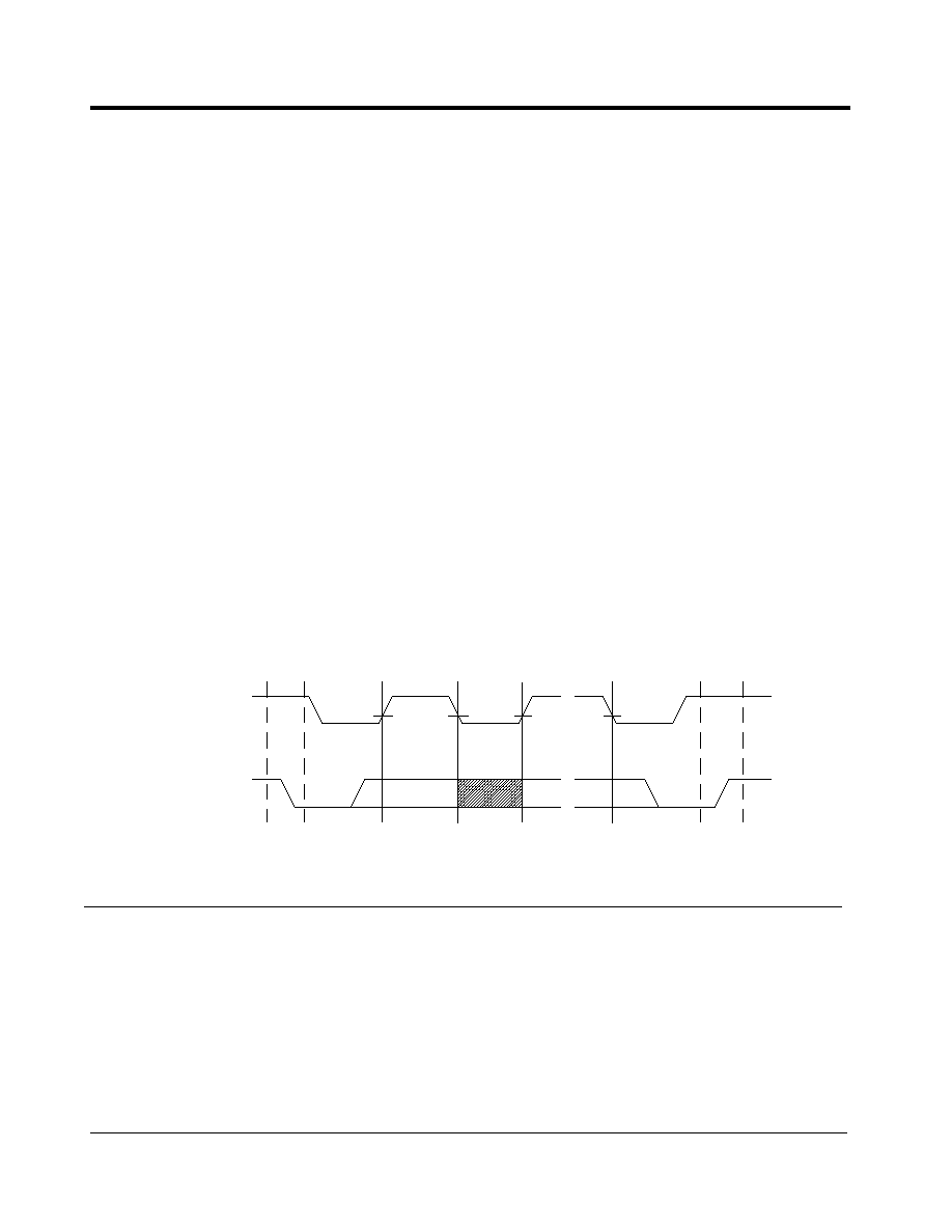
The write cycle is started by a start bit and ended by a stop bit. A start bit is a transition from high to
low of EEDIO when EEC is high. The operation terminates when EEDIO goes from low to high
when EEC is high (
Figure 5
). Following a start condition, the writing device must output the
address of the EEPROM. The most significant four-bit of the EEPROM address is the device type
identifier which has an address of 1010. The EEPROM device address should be set to 000.
Figure 5
EEPROM Start and Stop Bit
EECLK
EEDIO
START
BIT
Data or
Address
Valid
Data
Change
STOP BIT

AL104 Revision 1.0
9/00
Reference Only / Allayer Communications
32
3.15.3 Write Cycle Timing
The EECLK is an output from the AL104 while EEDIO is a bi-directional signal. When accessing
the EEPROM, the reset pin has to be held low or initialization of the AL104 must be finished before
a writing operation can begin.
Figure 6
EEPROM Write Cycle
3.15.4 Read Cycle Timing
Read operations are initiated in the same manner as write operations, with the exception that the R/
W bit of the EEPROM address is set to a "1."
Figure 7
EEPROM Read Cycle
S
A
A
A
S
8-Bit Word Address
8-Bit Data n
Start
Device
Address
Acknowledge
Acknowledge
Stop
Acknowledge
S
A
A
A
S
8-Bit Word Address
8-Bit Data n
Start
Device
Address
Acknowledge
Acknowledge
Stop
Acknowledge
S
A
A
A
No Acknowledge
Device
Address
Start
EEDIO
AL104 Revision 1.0
9/00
Reference Only / Allayer Communications
33
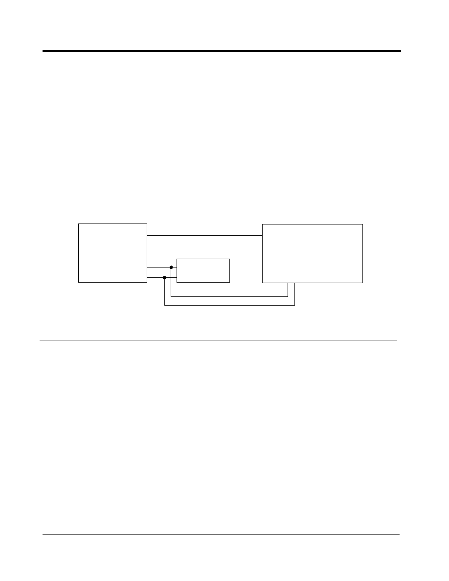
3.15.5 Reprogramming the EEPROM Configuration
There are two ways that the system can be reconfigured.
Figure 8
shows an application using the
parallel interface to reprogram the EEPROM. In this application, the parallel port holds the reset
pins low, which forces the EEDIO pins to go into high impedance. Once the pins are in high
impedance, the EEPROM can now be programmed by the parallel port. Once the parallel port
releases the reset pins, the devices will start to download the EEPROM data and reconfigure the
devices.
An alternate way of reconfiguring the system is to directly change the register settings of the
AL104. After initialization, the EEPROM interface can act as a virtual EEPROM. In order for this
method to work, the EEPROM's device address must be 000, while the AL104's address will be
100. The customer can now program the AL104 as an EEPROM. The read and write timing is the
same as an EEPROM.
Because you read as well as write to the AL104, the registers status can be read from the AL104.
This will serve as a very useful tool for diagnostic of an unmanaged switch.
Figure 8
EEPROM Using a Parallel Port
3.15.6 EEPROM Map
Table 18 shows the EEPROM address map cross-referenced to the register/bit set of the AL104.
Addresses 00 through 6D are for configuring the device. They are downloaded by the AL104 after
reset or power up. Since the AL104 registers are 16-bit wide, it takes two EEPROM addresses for
each AL104 register. Even numbered EEPROM addresses corresponds to the upper byte of the
AL104 registers while the odd numbered EEPROM addresses corresponds to the lower byte of the
AL104 registers.
Address 06 and 07 should be programmed as 0000 0001 and 0001 0100. The address 6F indicates
the last address entry. If no static address is used in the switch, the address 6F should be
programmed. Addresses 70 to FF are used for programming the static address entry.
The following format is an example of Static Entry 1, Address 70-77.
AL104
EEPROM
Parallel Port
EECLK
EEDIO
Reset

AL104 Revision 1.0
9/00
Reference Only / Allayer Communications
34
Note:
XXX represents port ID and YYY represents Trunk ID.
Table 18: Static Address Entry Format for EEPROM
EEPROM
ADDRESS
BIT
7
6
5
4
3
2
1
0
70
Reserved (Must be all zeros)
71
Reserved
Port ID 000XXX or Trunk ID 100YYY
72
MAC Address [47:40]
73
MAC Address [39:32]
74
MAC Address [31:24]
75
MAC Address [23:16]
76
MAC Address [15:8]
77
MAC Address [7:0]
Table 19: AL104 EEPROM Mapping
EEPROM PHYSICAL ADDRESS
DESCRIPTION
00-01
System Configuration I
02-03
System Configuration II
04-05
System Configuration III
06-07
Reserved (Value must be 0000 0001 0100)
08-09
Reserved
0A-0B
Vendor Specific PHY
0C-0D
Port Monitoring Configuration
0E-0F
Reserved
10-11
Reserved
12-13
Reserved
14-15
Reserved
16-17
Reserved
18-19
Reserved
1A-1B
Port 0 Configuration I
1C-1D
Port 0 Configuration II
1E-1F
Port 1 Configuration I

AL104 Revision 1.0
9/00
Reference Only / Allayer Communications
35
20-21
Port 1 Configuration II
22-23
Port 2 Configuration I
24-25
Port 2 Configuration II
26-27
Port 3 Configuration I
28-29
Port 3 Configuration II
2A-2B
Port 4 Configuration I
2C-2D
Port 4 Configuration II
2E-2F
Port 5 Configuration I
30-31
Port 5 Configuration II
32-33
Port 6 Configuration I
34-35
Port 6 Configuration II
36-37
Port 7 Configuration I
38-39
Port 7 Configuration II
3A-3B
Reserved (Must be all zero)
3C-3D
Port 0 VLAN Map
3E-3F
Reserved (Must be all zero)
40-41
Port 1 VLAN Map
42-43
Reserved (Must be all zero)
44-45
Port 2 VLAN Map
46-47
Reserved (Must be all zero)
48-49
Port 3 VLAN Map
4A-4B
Reserved (Must be all zero)
4C-4D
Port 4 VLAN Map
4E-4F
Reserved (Must be all zero)
50-51
Port 5 VLAN Map
52-53
Reserved (Must be all zero)
54-55
Port 6 VLAN Map
56-57
Reserved (Must be all zero)
58-59
Port 7 VLAN Map
5A-5B
Miscellaneous Register
5C-5D
Checksum
Table 19: AL104 EEPROM Mapping (Continued)

AL104 Revision 1.0
9/00
Reference Only / Allayer Communications
36
5E-5F
Port 0 to Trunk Port Assignment
60-61
Port 1 to Trunk Port Assignment
62-63
Port 2 to Trunk Port Assignment
64-65
Port 3 to Trunk Port Assignment
66-67
Port 4 to Trunk Port Assignment
68-69
Port 5 to Trunk Port Assignment
6A-6B
Port 6 to Trunk Port Assignment
6C-6D
Port 7 to Trunk Port Assignment
6E
Reserved
6F
Last Static Entry EEPROM Address
(Value must be 6F for no Static Entry)
70-77
Static Entry 1
78-7F
Static Entry 2
80-87
Static Entry 3
88-8F
Static Entry 4
90-97
Static Entry 5
98-9F
Static Entry 6
A0-A7
Static Entry 7
A8-AF
Static Entry 8
B0-B7
Static Entry 9
B8-BF
Static Entry 10
C0-C7
Static Entry 11
C8-CF
Static Entry 12
D0-D7
Static Entry 13
D8-DF
Static Entry 14
E0-E7
Static Entry 15
E8-EF
Static Entry 16
F0-F7
Static Entry 17
F8-FF
Static Entry 18
Table 19: AL104 EEPROM Mapping (Continued)

AL104 Revision 1.0
9/00
Reference Only / Allayer Communications
37
3.16 SGRAM Interface
All ports of the AL104 work in Store-And-Forward mode so that all ports can support both 10
Mbit/s and 100 Mbit/s data speed. The AL104 utilizes a central memory buffers pool, which is
shared by all ports within the same device. After a frame is received, it is passed across the SGRAM
interface and stored in the buffer. During transmit, the frame is retrieved from the buffer pool and
forwarded to the destination port.
The AL104 is designed to use 8 Mbit SGRAM or 16 Mbit SGRAM to achieve low cost and high
performance.
The SGRAM is accessed in Page Burst Access Mode for very high-speed access. This burst mode
is repeatedly sent to the same column. If burst mode reaches the end of the column address, it then
wraps around to the first column address (=0) and continues to count until interrupted by the new
read/write, pre-charge, or a burst stop command.
The AL104 will initialize the SGRAM automatically and pre-charges all banks and inserts eight
auto�refresh commands. It will also program the mode registers for the AL104's read and write
operations.
SGRAM essentially is a SDRAM. Dynamic memories must be refreshed periodically to prevent
data loss. The SGRAM uses refresh address counters to refresh automatically. The SGRAM Auto-
refresh command generates a pre-charge command internally in the SGRAM. The AL104 will
insert an auto-refresh command once every 15 microseconds.
4. Register Descriptions
Table 20: Register Tables Summary
REGISTER ID
REGISTER DESCRIPTION
REVERSE EEPROM
ADDRESS
00
System Configuration I
00,01
01
System Configuration II
02,03
02
System Configuration III
04,05
03
Reserved
06,07
04
Testing Register
08,09
05
Vendor Specific PHY Status
0A,0B
06
Port Monitoring Configuration
0C,0D
07-0C
Reserved
0E-19
0D
Port 0 Configuration I
1A,1B
0E
Port 0 Configuration II
1C,1D
0F
Port 1 Configuration I
1E,1F
10
Port 1 Configuration II
20,21

AL104 Revision 1.0
9/00
Reference Only / Allayer Communications
38
11
Port 2 Configuration I
22,23
12
Port 2 Configuration II
24,25
13
Port 3 Configuration I
26,27
14
Port 3 Configuration II
28,29
15
Port 4 Configuration I
2A,2B
16
Port 4 Configuration II
2C,2D
17
Port 5 Configuration I
2E,2F
18
Port 5 Configuration II
30,31
19 Port
6
Configuration
I
32,33
1A
Port 6 Configuration II
34,35
1B
Port 7 Configuration I
36,37
1C
Port 7 Configuration II
38,39
1D
Reserved 3A,3B
1E
Port 0 VLAN Map
3C,3D
1F
Reserved
3E.3F
20
Port 1 VLAN Map
40,41
21
Reserved
42,43
22
Port 2 VLAN Map
44,45
23
Reserved
46,47
24
Port 3 VLAN Map
48,49
25
Reserved
4A,4B
26
Port 4 VLAN Map
4C,4D
27
Reserved
4E,4F
28
Port 5 VLAN Map
50,51
29
Reserved
52,53
2A
Port 6 VLAN Map
54,55
2B
Reserved
56,57
2C
Port 7 VLAN Map
58,59
2D
Miscellaneous Register
5A,5B
2E
Port 0 to Trunk Port Assignment
5C,5D
Table 20: Register Tables Summary (Continued)

AL104 Revision 1.0
9/00
Reference Only / Allayer Communications
39
2F
Port 1 to Trunk Port Assignment
5E,5F
30
Port 2 to Trunk Port Assignment
60,61
31
Port 3 to Trunk Port Assignment
62,63
32
Port 4 to Trunk Port Assignment
64,65
33
Port 5 to Trunk Port Assignment
66,67
34
Port 6 to Trunk Port Assignment
68,69
35
Port 7 to Trunk Port Assignment
6A,6B
36-38
Reserved
6C-71
39
System Status Register
72,73
3A
Port 0 Operation Status
74,75
3B
Port 1 Operation Status
76,77
3C
Port 2 Operation Status
78,79
3D
Port 3 Operation Status
7A,7B
3E
Port 4 Operation Status
7C,7D
3F
Port 5 Operation Status
7E,7F
40
Port 6 Operation Status
80,81
41
Port 7 Operation Status
82,83
42
Indirect Resource Access Command
84,85
43
Indirect Resource Access Data I
86,87
44
Indirect Resource Access Data II
88,89
45
Indirect Resource Access Data III
8A,8B
46
Indirect Resource Access Data IV
8C,8D
47
Checksum
8E,8F
Table 20: Register Tables Summary (Continued)

AL104 Revision 1.0
9/00
Reference Only / Allayer Communications
40
5. System Configuration Registers
The System Configuration Registers 01 ~ 03 are global system configuration registers. The options
selected in these registers affect the overall system operation.
Table 21: System Configuration Register I (Register 00)
BIT
NAME
DESCRIPTION
15
OutQMgmt
Output Queue Management Method.
0: Output queue is not limited until the frame buffer is full.
1: Output queue is limited to the output queue watermark specified in
Reg.00 bits [7:6].
14
FloodCtl
Flooding Control. Control for the forwarding of unicast frames with
unknown destination received from the non-uplink ports.
0: Disable. Frames received with unknown unicast destination MAC
address will be forwarded to all the ports (excluding the receiving port)
within the VLANs specified at the receiving port.
1: Enable. Frames received with unknown unicast destination MAC
address will be forwarded to the uplink port specified for the receiving
port.
13
SecMgmt
Security Enforcement.
0: Auto security off. The security violation at a secured port will not
change its port state.
1: Auto security on. The security violation at a secured port will cause
the port into DISABLE state.
12
AgeEn
Switch Table Entry Aging Control.
0: Disable. The table aging process will be stopped.
1: Enable. The table aging process will be running to age every
dynamically learned table entry.
11
Reserved
Set value to 0.
10
Reserved
Reserved (Must set to 0).
9
PInMon
Port Incoming Frame Flow Monitoring Enable Control.
0: Disable
1: Enable
8
POutMon
Port Outgoing Frame Flow Monitoring Enable Control.
0: Disable
1: Enable
7~6
OutQWM
Output Queue Watermark. Watermark selection for output queues
and multicast queue full conditions.
16 Mbit/s SGRAM
00:128; 01:512; 10:768; 11:Test Mode.
8 Mbit/s SGRAM
00:64; 01:256; 10:384; 11:Test Mode.

AL104 Revision 1.0
9/00
Reference Only / Allayer Communications
41
5
SelRMIIP0
Select RMII Mode for Port 0.
0: RMII mode.
1: MII mode.
4
Reserved
Set value to 0.
3
L2Trunk
Layer 2 Trunk Loading Method.
0: Port based loading. Trunking decisions will be based on trunk port
assignment registers.
1: MAC address based loading. Trunking decisions will be based on
source port MAC addresses.
2
TimeoutEN
Frame Time Out Enable.
0: Device will timeout frames based on MaxDelay.
1: Device will not timeout frames.
1~0
Reserved
Reserved (Must set to 00).
Table 22: System Configuration Register II (Register 01)
BIT
NAME
DESCRIPTION
15~8
MaxAge
Maximum Age for Dynamically Learned MAC Entries.
0000 0000: 1 sec. to 1111 1111: 256 sec.
7~6
MaxDelay
Maximum Frame Transition Delay Through the Switch.
00: 1 second.
01: 2 seconds.
10: 3 seconds.
11: 4 seconds.
5~4
MaxStorm
Maximum Number of Broadcast Frames That Can Be Accumulated In
Each Input Frame Buffer.
00: 16 frames.
01: 32 frames.
10: 48 frames.
11: 64 frames.
3
SuperMAC
0: Disable. Device will perform the IEEE standard exponential back off
algorithm when a collision occurs.
1: Enable. When collisions occur, the AL104 will back off up to 3 slots.
2 REC
Retry
on
Excessive
Collision.
0: Normal collision handling.
1: Retry transmission after 16 consecutive collisions.
1~0
L2TbitSel
Select the Bits Position for MAC Address to Trunk Assignment.
00: Source MAC Address [1:0].
01: Source MAC Address [3:2].
10: Source MAC Address [5:4].
11: Source MAC Address [7:6].
Table 21: System Configuration Register I (Register 00) (Continued)

AL104 Revision 1.0
9/00
Reference Only / Allayer Communications
42
Table 23: System Configuration Register III (Register 02)
BIT
NAME
DESCRIPTION
15
Reserved
Reserved (Must set to 0).
14
DISPHYReset
PHY Reset Option.
0: Reset PHY on link down.
1: Don't reset PHY on link down.
13
Skip_Reg6
Enable Skip Register 6 Read During Auto-negotiation for Seeq
PHY.
0: Don't skip.
1: Skip
12~11
Reserved
Reserved (Must set to 0).
10 AgeRes
Age
Resolution.
0: Normal aging.
1: Slow down aging.
9
BpIPGSelEn
Backpressure IPG Select Enable.
0: Backpressure IPG = 96BT.
1: According to BpIPGSel value.
8
IPG64
IPG Control.
0: IPG = 96BT
1: IPG = 64BT
7~6
Reserved
Reserved
5
SG16M
SGRAM Select.
0: 8 Mbit SGRAM.
1: 16 Mbit SGRAM.
4
BPCOL
Back Pressure Control.
0: Carrier based.
1: Collision based.
3~2
BpIPGSel
Backpressure IPG Select.
00: 48BT; 01: 56BT; 10:65BT; 11: 72BT.
1
Reserved
Reserved
0
BCdrop_SC
0: Flow control multicast.
1: Flow control multicast/broadcast.

AL104 Revision 1.0
9/00
Reference Only / Allayer Communications
43
Reserved Register (Register 03)
Note:
This register is reserved for Allayer's use. The bits should be set as 0000 0001
0001 0100.
Testing Register (Register 04)
This register is reserved for Allayer's use. The bits should be set as 0000 0000 0000 1000.
Note:
Most of the bits in this register are reserved of the factory testing except for the
WmarkSel bits. This bit sets the level of buffer to trigger backpressure to
eliminate buffer overflow.
Note:
This register is used to program vendor-specific PHY options. It is also used
for programming the Vendor Specific PHY register location and bit location of
the operation status.
Table 24: Testing Register (Register 04)
BIT
NAME
DESCRIPTION
15~12
Reserved
Reserved
11~10
WmarkSel
Backpressure Watermark Select.
00: Backpressure if available block count < 4.
01: Backpressure if available block count < 8.
10: Backpressure if available block count < 16.
11: Test Mode.
Each block is 2K byte.
9~0
Reserved
Reserved
Table 25: Vendor Specific PHY register (Register 05)
BIT
NAME
DESCRIPTION
15
PHYAD
Setting this bit to "1" will program the MDIO PHY address to 16 to 23.
14
MclkSpd
Setting this bit to "1" will reduce the MDIO clock speed to 17KHz.
13
PortOrder
Setting this bit to "1" will reverse the PHY ID/port number of the switch.
12~8
PHYOpReg
PHY's Operation Status Register Number.
7~4
PHYSpBit
PHY's Data Rate Status Register Bit Number.
3~0
PHYDxMode
PHY's Operating Duplex Mode Status Register Bit Number.

AL104 Revision 1.0
9/00
Reference Only / Allayer Communications
44
Reserved Registers (Registers 07 to 0C)
These registers are reserved and must be set to all zero.
Port Configuration Registers (Registers 0D to 1C)
Registers 0D to 1C are for local port configuration. There are two port configurations per port. Port
0 port configuration uses register 0D and 0E, Port 1 register 0F and 10, etc.
Table 26: Port Monitoring Configuration (Register 06)
BIT
NAME
DESCRIPTION
15
Reserved
Reserved
14~10
MdPID
Monitored Port ID.
9~5
MgIPID
Snooping Port ID for incoming frame flow.
4~0
MgOPID
Snooping Port ID for outgoing frame flow.
Table 27: Port Configuration Register I
BIT
NAME
DESCRIPTION
15~10
UpLinkID
Uplink ID Associated with the Port.
000YYY: Port ID with XX as the device ID and YYY as the port ID.
10000N: Trunk ID with XX as the device ID and N as the trunk ID.
Others: Reserved.
9
Tmember
Trunk Member Port.
0: Individual port.
1: Member of trunk port.
8
Reserved
Reserved (Set to 0).
7
StormCTL
Broadcast Storm Control Enable.
0: Storm control disable. The broadcast frame will not be throttled.
1: Storm control enable. If the accumulated number of broadcast
frames in the input buffer of the port is over the threshold specified in
the system configuration register, new incoming broadcast frames will
be discarded until the number has been reduced below the threshold.
6
Security
Intrusion Protection. Security control for the frames received from non-
uplink ports.
0: Security off. The forwarding decision made about frames received
from the port will not involve the source MAC address checking.
1: Security on. The frames received from the port with unknown
source MAC address or with source MAC address learned previously
from another port will be discarded.
5
Reserved
Reserved (Must set to 0)

AL104 Revision 1.0
9/00
Reference Only / Allayer Communications
45
4
LrnDis
Learning Disable.
0: Source address from this port will be learned.
1: Source address from this port will not be learned.
3~2
Reserved
Must set to 11.
1~0
Reserved
Reserved (Must set to 0).
Table 28: Port Configuration Register II
BIT
NAME
DESCRIPTION
15~14
Reserved
Reserved (Must set to 0).
13
Reserved
Reserved (Must set to 0).
12
SkipANDone
Ignore Auto-Negotiation Complete and Wait for Link Up.
11
FlowCtrlFdEn
Flow Control Full Duplex Enable.
10
FlowCtrlHdEn
Flow Control Half Duplex Enable.
9~6
MDIOCfg[3:0]
MDIO Configuration.
0001: Master mode PHY management.
0010: Slave mode PHY management.
0111: Force mode.
5
MDIODis
MDIO Disable.
0: MDIO is enabled.
1: MIDO is disabled.
4
LinkUp
This bit is not relevant when MDIO is enabled. When MDIO is
disabled, this bit forces the port into link up or link down state.
3
PrtMode100F
Force 100 Full Duplex Mode.
2
PrtMode100H
Force 100 Half Duplex Mode.
1
PrtMode 10F
Force 10 Full Duplex Mode.
0
PrtMode 10H
Force 10 Half Duplex Mode.
Table 27: Port Configuration Register I (Continued)

AL104 Revision 1.0
9/00
Reference Only / Allayer Communications
46
Port VLAN Map Registers (Registers 1E to 2C)
These registers provide the VLAN map for each port. Registers 1D, 1F, 21, 23, 25, 27, 29, and 2B
are reserved. The values for these reserved registers should be all zero.
A VLAN worksheet is provided in Appendix I.
Table 29: Port VLAN Map Registers (Registers 1E to 2C)
BIT
NAME
DESCRIPTION
15~8
Reserved
Should be set to 0.
7
Port7VLAN
Port VLAN Corresponding to the Port 7.
0: Non-member port.
1: Member port.
6
Port6VLAN
Port VLAN Corresponding to the Port 6.
0: Non-member port.
1: Member port.
5
Port5VLAN
Port VLAN Corresponding to the Port 5.
0: Non-member port.
1: Member port.
4
Port4VLAN
Port VLAN Corresponding to the Port 4.
0: Non-member port.
1: Member port.
3
Port3VLAN
Port VLAN Corresponding to the Port 3.
0: Non-member port.
1: Member port.
2
Port2VLAN
Port VLAN Corresponding to the Port 2.
0: Non-member port.
1: Member port.
1
Port1VLAN
Port VLAN Corresponding to the Port 1.
0: Non-member port.
1: Member port.
0
Port0VLAN
Port VLAN Corresponding to the Port 0.
0: Non-member port.
1: Member port.

AL104 Revision 1.0
9/00
Reference Only / Allayer Communications
47
Table 30: Miscellaneous Register (Register 2D)
BIT
NAME
DESCRIPTION
15~14
Reserved
Set value to 0.
13
ET16K
16K External Table.
0: 8K external table.
1: 16K external table.
12
ETEna
External MAC Address Table Enable.
0: External table is disabled.
1: External table is enabled.
11
Reserved
Set value to 0.
10
L2DASA
Select the Algorithm for MAC Based Loading.
0: SA only.
1: SA and DA.
9
L2Fail
Trunk Link Fail Over.
0: Don't fail over when a trunk port fails.
1: Allow link fail over for trunking.
8
L2MAP
Enable 2 or 3 Port MAC Based Trunking Option.
0: Disable
1: Enable
7~4
TrunkMap1
MAC Based Trunk Port Mapping for Trunk 1.
0: Non-trunk port.
1: Trunk port.
3~0
TrunkMap0
MAC Based Trunk Port Mapping for Trunk 0.
0: Non-trunk port.
1: Trunk port.

AL104 Revision 1.0
9/00
Reference Only / Allayer Communications
48
Port Trunk Port Assignment Registers (Registers 2E to 35)
The Port to Trunk Port assignment register assigns a port to a trunk for port-based load balancing
trunking. A port to trunk port work sheet is provided at the end of the data sheet.
Table 31: Port Trunk Port Assignment Registers (Registers 2E to 35)
BIT
NAME
DESCRIPTION
15~4
Reserved
Should be set to 0.
3~2
Trunk1
Trunk Port of Trunk 1.
00: Port 4.
01: Port 5.
10: Port 6.
11: Port 7.
1~0
Trunk0
Trunk Port of Trunk 0.
00: Port 0.
01: Port 1.
10: Port 2.
11: Port 3.
Table 32: System Status Register (Register 39)
BIT
NAME
DESCRIPTION
15
EPTimeOut
EEPROM Time Out.
0: EEPROM initialized the device.
1: EEPROM is not found. Default configuration.
14
EEPROM_Err
EEPROM Checksum error.
13
Sgraminitdone
SGRAM Initialization Done.
0: SGRAM initialization is not done.
1: SGRAM initialization is done.
12
Sraminitdone
SRAM Initialization Done.
0: SRAM initialization is not done.
1: SRAM initialization is done.
11
Reginitdone
Register Initialization Done.
0: AL104 register initialization is not done.
1: AL104 register initialization is done.
10~7
TrafCnt
Traffic Counter.
0000: Minimum traffic.
1111: Maximum traffic.
6~4
Reserved
Reserved
3~0
Version ID
0101: AL104

AL104 Revision 1.0
9/00
Reference Only / Allayer Communications
49
Port Operation Status Registers (Register 3A to 41)
Registers 3A to 41 are status indication on a per port basis. These are read only register. Port 0 port
status is in register 3A; Port 1 register 3B...and port 7 register 41.
Table 33: Port Operation Status Registers (Register 3A to 41)
BIT
NAME
DESCRIPTION
15
LinkFail
Port Link Status.
0: Normal
1: Fail
14
PHYError
Port PHY Status.
0: Normal
1: Error
13 Sviolation
Port
Security
Violation.
0: Normal
1: Violation
12
FlowCtrl
Flow Control.
If port mode ([1:0]) is 2'b01 or 2'b11:
0: Pause disable.
1: Pause enable.
If port mode ([1:0]) is 2'b00 or 2'b10:
0: Back pressure based on CRS.
1: Back pressure based on collision.
11
Stormed
Port Broadcast Storm Status.
0: Normal
1: Stormed
10
InBFull
Port Input Buffer Full Status.
0: Normal
1: Input buffer full experienced.
9
TblUNAVL
Table Entry Unavailability for MAC Learning.
0: Normal
1: Unavailability experienced.
8
Jabbered
Port Jabber Status.
0: Normal
1: Jabber experienced.
7
LateCOL
Port Late Collision Status.
0: Normal
1: Late collision experienced.
6
TxPaused
Port Transmit Pause Status.
0: No transmit pause experienced.
1: Transmit pause experienced.
5
CRSLoss
Port Carrier Sense Loss During Transmission Status.
0: No carrier sense loss experienced.
1: Carrier sense loss experienced.

AL104 Revision 1.0
9/00
Reference Only / Allayer Communications
50
Indirect Resource Access Command Register (Register 42)
Indirect resource access command allows the management (Reverse EEPROM Method) to access
other resources other than the AL104 register values. PHY registers, both internal and external
MAC address tables, and SGRAM contents can be accessed using this command.
4
FalseCRS
False Carrier Status.
3
Underflow
Transmit Queue Underflow Status.
0: Normal
1: Underflow experienced.
2
TimeOut
Frame Time Out.
0: Normal
1: Frame time out experienced.
1~0
PortMode
Port Operating Mode.
00: 10Mb half-duplex.
01: 10Mb full-duplex.
10: 100Mb half-duplex.
11: 100Mb full-duplex.
Table 34: Indirect Resource Access Command Register (Register 42)
BIT
NAME
DESCRIPTION
15
CmdDone
Command Done. Clear this bit to execute a new command. When
finished with the command, the AL104 will set the bit back to "1."
0: Execute new command.
1: Command done.
14
Operation
Read/Write Operation Command.
0: Read operation.
1: Write operation.
13~11
ResType
Type of Accessed Resource.
000: PHY registers.
001: EEPROM.
010: SGRAM.
011: MAC address table 1;
Read: MAC table address read.
Write: MAC address learn.
100: MAC address table 2;
Read: MAC address search.
Write: MAC address delete.
101-111: Reserved
10
ExtRD
External MAC Address Table Read.
If ResType = 011 and Operation = 0
0: On-chip address table read.
1: Off-chip address table read.
Table 33: Port Operation Status Registers (Register 3A to 41) (Continued)

AL104 Revision 1.0
9/00
Reference Only / Allayer Communications
51
Note:
Indirect Resource Access Data I through IV is used with the indirect resource
access command.
9~0
ResAddr
The address of the entry within the accessed resource.
Table 35: Indirect Resource Access Data I Register (Register 43)
BIT
NAME
DESCRIPTION
15~0
IRAData
Indirect Resource Access Data 1.
Table 36: Indirect Resource Access Data II Register (Register 44)
BIT
NAME
DESCRIPTION
15~0
IRAData
Indirect Resource Access Data 2.
Table 37: Indirect Resource Access Data III Register (Register 45)
BIT
NAME
DESCRIPTION
15~0
IRAData
Indirect Resource Access Data 3.
Table 38: Indirect Resource Access Data IV Register (Register 46)
BIT
NAME
DESCRIPTION
15~0
IRAData
Indirect Resource Access Data 4.
Table 39: Check Sum (Register 47)
BIT
NAME
DESCRIPTION
15~8
CheckSum
Check Sum Value of AL104 Register Contents.
7~0
Reserved
Table 34: Indirect Resource Access Command Register (Register 42)

AL104 Revision 1.0
9/00
Reference Only / Allayer Communications
52
6. Timing Requirements
Note:
Delays are assuming 10pf loading on the output pins.
Figure 9
RMII/MII Transmit Timing Diagram
Table 40: MII Transmit Timing
SYMBOL
DESCRIPTION
MIN
TYP
MAX
UNIT
t
tdv
TXCLK to TXD valid time.
4
-
12
ns
t
txev
TXCLK to TXEN valid time.
4
-
12
ns
Table 41: RMII Transmit Timing
SYMBOL
DESCRIPTION
MIN
TYP
MAX
UNIT
t
tdv
TXCLK to TXD valid time.
3
-
9
ns
t
txev
TXCLK to TXEN valid time.
3
-
14
ns
t
txev
t
tdv
DATA
TXCLK
DATA
TXEN
TXD
t
txev
DATA
DATA
DATA
DATA
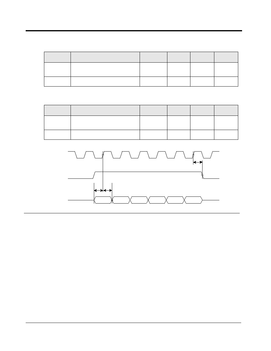
AL104 Revision 1.0
9/00
Reference Only / Allayer Communications
53
Figure 10
RMII/MII Receive Timing Diagram
Table 42: MII Receive Timing
SYMBOL
DESCRIPTION
MIN
TYP
MAX
UNIT
t
rxds
RX_DV, RXD, RX_ER, setup
time.
10
-
-
ns
t
rxdh
RX_DV, RXD, RX_ER hold time.
5
-
-
ns
Table 43: RMII Receive Timing
SYMBOL
DESCRIPTION
MIN
TYP
MAX
UNIT
t
rxds
RX_DV, RXD, RX_ER, setup
time.
3
-
-
ns
t
rxdh
RX_DV, RXD, RX_ER hold time.
3
-
-
ns
t
rxds
t
rxdh
DATA
RXCLK
DATA
RXDV
RXD
t
rxdh
DATA
DATA
DATA
DATA

AL104 Revision 1.0
9/00
Reference Only / Allayer Communications
54
Figure 11
PHY Management Read Timing
Table 44: PHY Management (MDIO) Read Timing
SYMBOL
DESCRIPTION
MIN
TYP
MAX
UNIT
t
ch
MDC high time
420
425
430
ns
t
cl
MDC low time
420
425
430
ns
t
mc
MDC period
840
850
860
ns
t
ms
MDIO setup time
10
-
15
ns
t
mh
MDIO hold time
10
-
-
ns
t
cl
t
ch
MDC
MDIO
t
mc
t
ms
t
mh
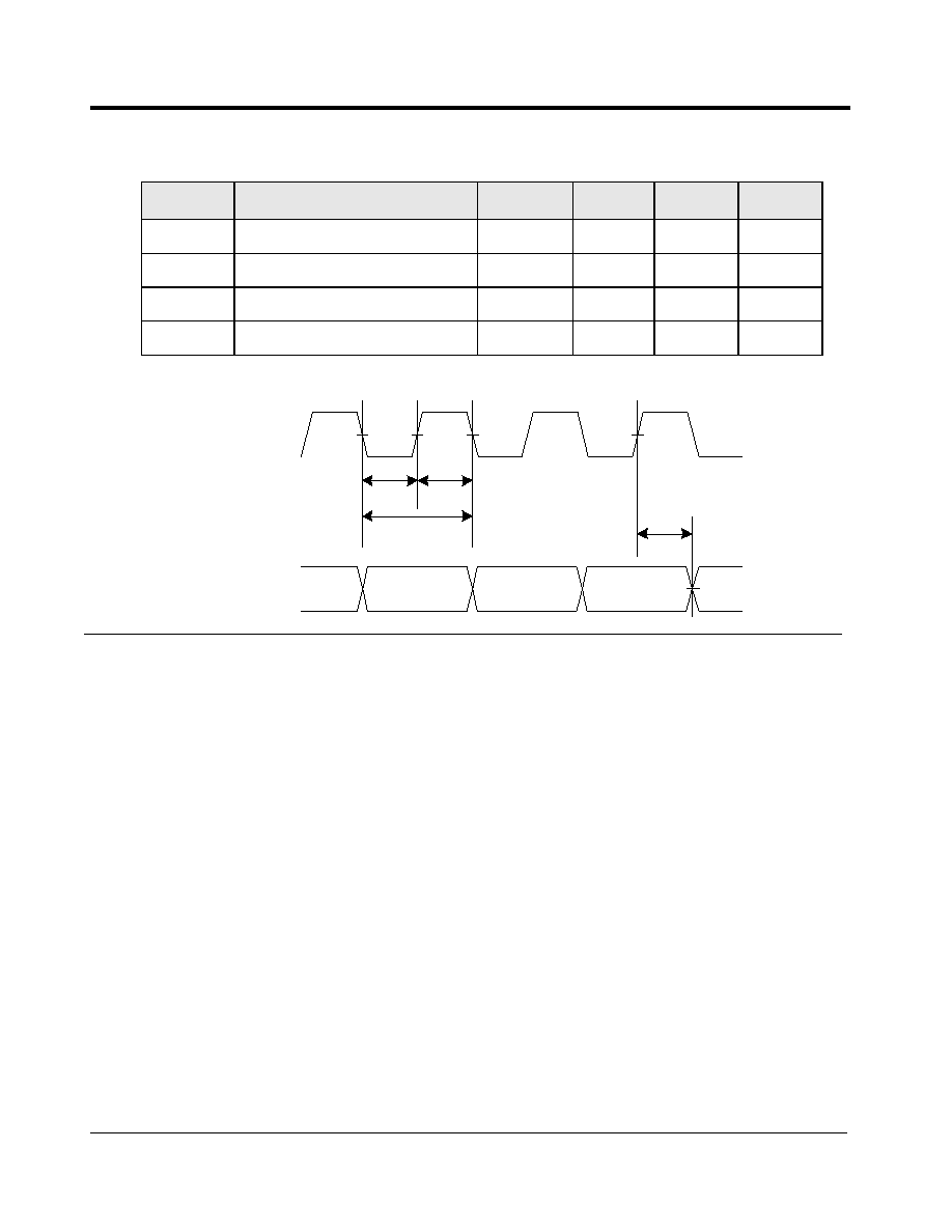
AL104 Revision 1.0
9/00
Reference Only / Allayer Communications
55
Figure 12
PHY Management Write Timing
Table 45: PHY Management (MDIO) Write Timing
SYMBOL
DESCRIPTION
MIN
TYP
MAX
UNIT
t
ch
MDC high time
420
425
430
ns
t
cl
MDC low time
420
425
430
ns
t
mc
MDC period
840
850
860
ns
t
d
MDIO output delay
40
-
52
ns
t
cl
t
ch
MDC
MDIO
t
mc
t
d

AL104 Revision 1.0
9/00
Reference Only / Allayer Communications
56
Figure 13
SGRAM Refresh Timing
Table 46: SGRAM Refresh Timing
SYMBOL
DESCRIPTION
MIN
TYP
MAX
UNIT
t
AH
Access hold time
1
-
-
ns
t
AS
Access setup time
3
-
-
ns
t
CH
PBCS#, PBRAS#, PBWE# hold time
1
-
-
ns
t
CHI
Clock high level width
3.5
-
-
ns
t
CK
System clock cycle time
10
-
-
ns
t
CKH
CKE hold time
1
-
-
ns
t
CKS
CKE setup time
3
-
-
ns
t
CL
Clock low level width
3.5
-
-
ns
t
CS
PBCS#, PBRAS#, PBWE# setup time
3
-
-
ns
t
RP
Precharge command period
30
-
-
ns
t
RC
Auto refresh to auto refresh period
90
-
-
ns
t
CHI
t
CK
t
CL
Precharge
NOP
NOP
Auto
Refresh
NOP
Auto
Refresh
Active
PBCLK
CKE
Command
Address
BANK
BANK
ROW
t
RP
t
RC
t
RC
t
CKH
t
CKS
t
CH
t
CS
Don't Care

AL104 Revision 1.0
9/00
Reference Only / Allayer Communications
57
Note:
This timing requirement is for a SGRAM running at CAS Latency 2. Typically
a -8 speed grade SGRAM needs to be used.
Table 47: SGRAM Read Timing
SYMBOL
DESCRIPTION
MIN
TYP
MAX
UNIT
t
AC
Access time
-
-
10
ns
t
AH
Access hold time
2
-
-
ns
t
AS
Access setup time
2.5
-
-
ns
t
CH
PBCS#, PBRAS#, PBWE# hold
time
1
-
-
ns
t
CHI
Clock high level width
3
-
-
ns
t
CK
System clock cycle time
13
-
-
ns
t
CKH
CKE hold time
2
-
-
ns
t
CKS
CKE setup time
3
-
-
ns
t
CL
Clock low level width
3
-
-
ns
t
CS
PBCS#, PBRAS#, PBWE#
setup time
2.5
-
-
ns
t
HZ
Data out high impedance time
-
-
8
ns
t
LZ
Data out low impedance time
2
-
-
ns
t
OH
Data out hold time
2
-
-
ns
t
RAS
Active to precharge command
period
48
-
-
ns
t
RCD
Active to read delay
24
-
-
ns
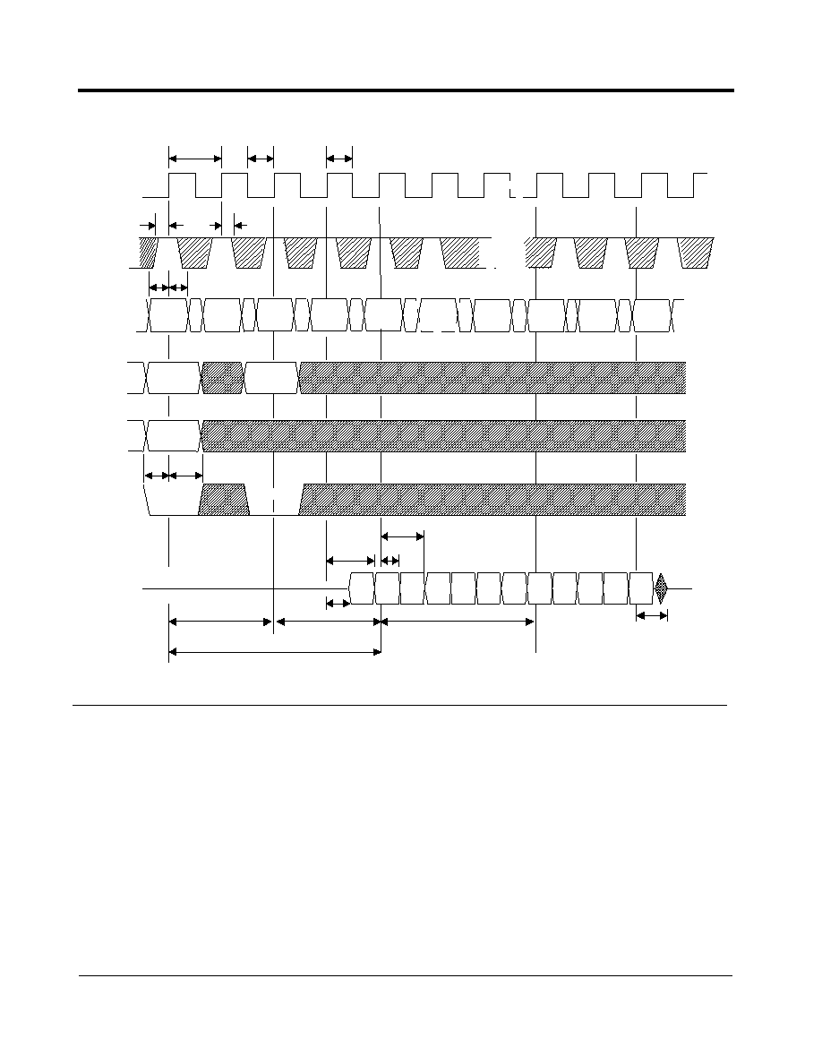
AL104 Revision 1.0
9/00
Reference Only / Allayer Communications
58
Figure 14
SGRAM Read Timing
t
CHI
t
CK
PBCLK
CKE
t
RCD
(Bank 0)
CAS Latency
256 location within the same row
t
CS
t
CH
t
CKH
tCKS
BANK 0
Active
NOP
NOP
READ
NOP
NOP
Command
NOP
BURST
TERM.
A0-A7
ROW
t
RAS
(Bank 0)
BANK 0
PBBA
PBD
ROW
column m
A8
t
AH
t
LZ
t
AC
t
OH
Dout
m
Dout
m+1
Dout
m+2
Dout
m-1
Dout
m
Dout
m+1
t
AC
NOP
NOP
t
HZ
t
CL
t
AS

AL104 Revision 1.0
9/00
Reference Only / Allayer Communications
59
Note:
This timing requirement is for a SGRAM running at CAS Latency 2. Typically
a -8 speed grade SGRAM needs to be used.
Table 48: SGRAM Write Timing
SYMBOL
DESCRIPTION
MIN
TYP
MAX
UNIT
t
AH
Access hold time
2
-
-
ns
t
AS
Access setup time
2.5
-
-
ns
t
CH
PBCS#, PBRAS#, PBWE# hold
time
1
-
-
ns
t
CHI
Clock high level width
3
-
-
ns
t
CK
System clock cycle time
13
-
-
ns
t
CKH
CKE hold time
2
-
-
ns
t
CKS
CKE setup time
3
-
-
ns
t
CL
Clock low level width
3
-
-
ns
t
CS
PBCS#, PBRAS#, PBWE#
setup time
2.5
-
-
ns
t
DH
Data in hold time
1
-
-
ns
t
DS
Data in setup time
2.5
-
-
ns
t
RAS
Active to precharge command
period
48
-
100,000
ns
t
RCD
Active to read delay
24
-
-
ns

AL104 Revision 1.0
9/00
Reference Only / Allayer Communications
60
Figure 15
SGRAM Write Timing
t
CHI
PBCLK
CKE
t
RCD
(Bank 0)
256 location within the same row
t
CS
t
CH
t
CKH
t
CKS
BANK 0
Active
NOP
NOP
write
NOP
NOP
Command
NOP
BURST
TERM.
A0-A7
ROW
t
RAS
(Bank 0)
BANK 0
PBBA
PBD
ROW
column m
A8
t
AS
t
AH
t
DS
t
DH
NOP
NOP
Din m
Din
m+1
Din
m+2
Din
m+3
Din
m-1
Din m
Don't Care
Undefined
t
CK
t
CL

AL104 Revision 1.0
9/00
Reference Only / Allayer Communications
61
7. Electrical Specifications
Note:
Operation at absolute maximum ratings for extended periods of time could
cause permanent damage to the device.
Table 49: Maximum Ratings
DC Supply Voltage Vcc (3.3V)
-0.3V ~ + 3.6V
DC Supply Voltage (VccM)
-0.6V ~ + 6.0V
DC Input Voltage
-0.3 ~ Vcc + 0.3V
DC Output Voltage
-0.3 ~ Vcc + 0.3V
DC Supply Voltage to MII
-0.6V to 6.0V
DC Input Voltage to MII
-0.6 to VccM + 0.3V
DC Output Voltage to MII
-0.6 to VccM + 0.3V
Storage Temperature
-55
o
C to +150
o
C
Table 50: Recommended Operation Conditions
Supply Voltage
3.3V � 0.3V
Supply Voltage (VccM)
5.0V � 0.5V
Operating Temperature
0
o
C to 70
o
C
Power Dissipation
1.7 W (typical)
Table 51: DC Electrical Characteristics
PARAMETER
DESCRIPTION
MIN
TYP
MAX
UNIT
Voh
Output voltage-high, Ioh=4mA
2.4
-
-
V
Vol
Output voltage-low, Ioh=4mA
-
-
0.4
V
Ioz
High impedance state output current
-10
-
10
uA
Iih
Input current-high
(With no pull-up or pull-down)
-10
-
10
uA
Iil
Input current-low
(With no pull-up or pull-down)
-10
-
10
uA
Vih
Input high voltage
0.7*Vcc
-
-
V
Vil
Input low voltage
-
-
0.3*Vcc
V
Icc
Supply current
-
-
-
mA

AL104 Revision 1.0
9/00
Reference Only / Allayer Communications
62
8. AL104 Mechanical Data
208-Pin PQFP Package
Figure 16
AL104 Mechanical Dimensions
0.20 � 0.05
0.50 � 0.1
28.00 � 0.13
30.6 � 0.3
0.10 min.
3.68 max.
1.30 � 0.20
0.50 � 0.20
0.10
3.23 � 0.12
25.5

AL104 Revision 1.0
9/00
Reference Only / Allayer Communications
63
9. Appendix I (VLAN Mapping Work Sheet)
PORT
BIT
PO
R
T
0
/
R
E
G.
1E
POR
T
1
/
R
E
G.
20
POR
T
2
/
R
E
G.
22
POR
T
3
/
R
E
G.
24
POR
T
4
/
R
E
G.
26
POR
T
5
/
R
E
G.
28
POR
T
6
/
R
E
G.
2A
POR
T
7
/
R
E
G.
2C
7
7
6
6
5
5
4
4
3
3
2
2
1
1
0
0

AL104 Revision 1.0
9/00
Reference Only / Allayer Communications
64
10. Appendix II (Port to Trunk Port Assignment Work Sheet)
TRUNK
/ PORT
BIT/
VALUE
PO
R
T
0
/
R
E
G.
2E
PO
R
T
1/RE
G
.
2F
POR
T
2
/
R
E
G.
30
POR
T
3
/
R
E
G.
31
POR
T
4
/
R
E
G.
32
POR
T
5
/
R
E
G.
33
POR
T
6
/
R
E
G.
34
POR
T
7
/
R
E
G.
35
TRUNK 1
BITS
3, 2
7
11
6
10
5
01
4
00
TRUNK 0
BITS
1, 0
3
11
2
10
1
01
0
00

AL104 Revision 1.0
9/00
Reference Only / Allayer Communications
65
11. Appendix III (Suggested Memory Components)
Note:
This is only a partial list of memory components that can be used in Allayer
devices.
The AL104 uses Frame Buffer SGRAM chips that require 32-bit wide SGRAM or SDRAM, that is
80 MHz or faster with CAS latency 2.
The AL104 uses MAC Table Memory SSRAM chips that require Sync Burst pipelined SSRAM, 80
MHz or faster.
The following lists some of the memory that can be used in the AL104.
DEVICE
FREQ.
8 Mbit SGRAM
16 Mbit SGRAM
SSRAM
AL104
80 MHz
MoSys -
MG802C256Q-10
Etron -
EM635327Q-8
MoSys -
MG802C512L-8
Etron -
EM636227Q-8
Winbond -
W971632AF-7
Micron -
MT58LC64K32D8LG-11
IDT - 71V632S6PF

AL104 Revision 1.0
9/00
Reference Only / Allayer Communications
66
Rev. History (Prelim. 1.2 to 1.3)
1. Table 3: M2RXD1 changed to pin 52 and M2RXD0 changed to pin 51.
2. Table 13: SYSCLK is a 80MHz system clock.
3. Table 15: Register numbers have been changed.
4. Table 16: Register numbers have been changed.
5. Table 20: Section and table headings have been changed.
6. Table 21: Bits 8 and 9 have been added.
7. Table 23: Bit 13 has been added.
8. Table 32: Bit 14 has been added.
Rev. History (Prelim. 1.3 to 1.3a)
1. Changes were for layout of the Table of Contents.
2. Added memory information to appendix III.
3. Added new PHY management timing diagrams.
4. Added new RMII and MII timing diagrams.
Rev. History Prelim. 1.3a to Prelim. 1.4
1. Cleaned up SGRAM write and read tables.
2. Corrected queue management information.
Rev. History (Prelim. 1.4 to Rev. 1.0)
1. Fully released document.

Reference Only / Allayer Communications
Index
A
Address Learning 18
AL104 EEPROM Mapping 34
AL104 Interface Block Diagram 15
AL104 Mechanical Data 62
AL104 Overview 5
AL104 Pin Diagram 6
Appendix I (VLAN Mapping Work Sheet) 63
Appendix II (Port to Trunk Port Assignment Work Sheet) 64
Appendix III (Suggested Memory Components) 65
B
Broadcast Storm Control 17
C
Check Sum (Register 47) 51
D
Data Reception 16
DC Electrical Characteristics 61
E
EEPROM Interface 13, 31
EEPROM MAP 33
EEPROM Using a Parallel Port 33
External Address Table SRAM Interface 12
F
Flow Control 26
Frame Filtering 16
Frame Forwarding 17
Frame Generation 18
Frame Transmission 18
Full Duplex Flow Control (802.3X) 26
H
Half Duplex Flow Control (Backpressure) 26
Half Duplex Mode Operation 18
I
Illegal Frame Length 16
Indirect Resource Access Command Register (Register 42) 50
Indirect Resource Access Data III Register (Register 45) 51
Indirect Resource Access Data IV Register (Register 46) 51
L
Load Balancing 21
Long Frames 16
M
MAC Based Load Balancing Set Up 24
Maximum Ratings 61
Media Independent Interface (MII) 29
MII Receive Timing 53
MII Transmit Timing 52
MII/RMII Interface Port 0 7
Miscellaneous Pins 14
Miscellaneous Register (Register 2D) 47
N
Non Auto-negotiation Mode 30
O
Other PHY Options 30
P
PHY Management 29
PHY Management (MDIO) Read Timing 54
PHY Management (MDIO) Write Timing 55
PHY Management Master Mode 29
PHY Management MDIO 29
PHY Management Slave Mode 30
Pin Descriptions 7
Port Based Trunk Loading 22
Port Monitoring 28
Port Monitoring Configuration (Register 06) 44
Power Interface 14
Q
Queue Management 27
R
Read Cycle Timing 32
Recommended Operation Conditions 61
Reduced Media Independent Interface (RMII) 28
Register Tables Summary 37
Reprogramming the EEPROM Configuration 33
Reserved Register (Register 03) 43
RMII Interface Port 1 8
RMII Interface Port 2 8
RMII Interface Port 3 8
RMII Interface Port 4 9
RMII Interface Port 5 9
RMII Interface Port 6 10
RMII Interface Port 7 10
RMII Receive Timing 53
RMII Transmit Timing 52
S
Secure Mode Operation 18
SGRAM Interface 11, 37
SGRAM Refresh Timing 56
SGRAM Write Timing 59
Static Address Entry Format for EEPROM 34
System Block Diagram 1
System Configuration Register I 40
System Configuration Register II (Register 01) 41
System Configuration Register III (Register 02) 42
System Initialization 31
T
Testing Register (Register 04) 43
Timing Requirements 52
Trunk Fail Over 21
Trunk Port Assignment 22
Trunking (Port Aggregation) 21

AL104 Revision 1.0
9/00
Reference Only / Allayer Communications
68
U
Uplink Port 27
V
Vendor Specific PHY register (Register 05) 43
VLAN Mapping for MAC Based Loading Trunk 25
VLAN Mapping for Port Based Load Balancing Trunk 23
VLAN Support 19
W
Write Cycle Timing 32