DS000011 Rev2.3 July `99
©
1999 REG No 277 4001, ENGLAND.
Page 1
M
INIATURE
RF R
ECEIVER
D
ECODER
M
ODULES
.
DESCRIPTION
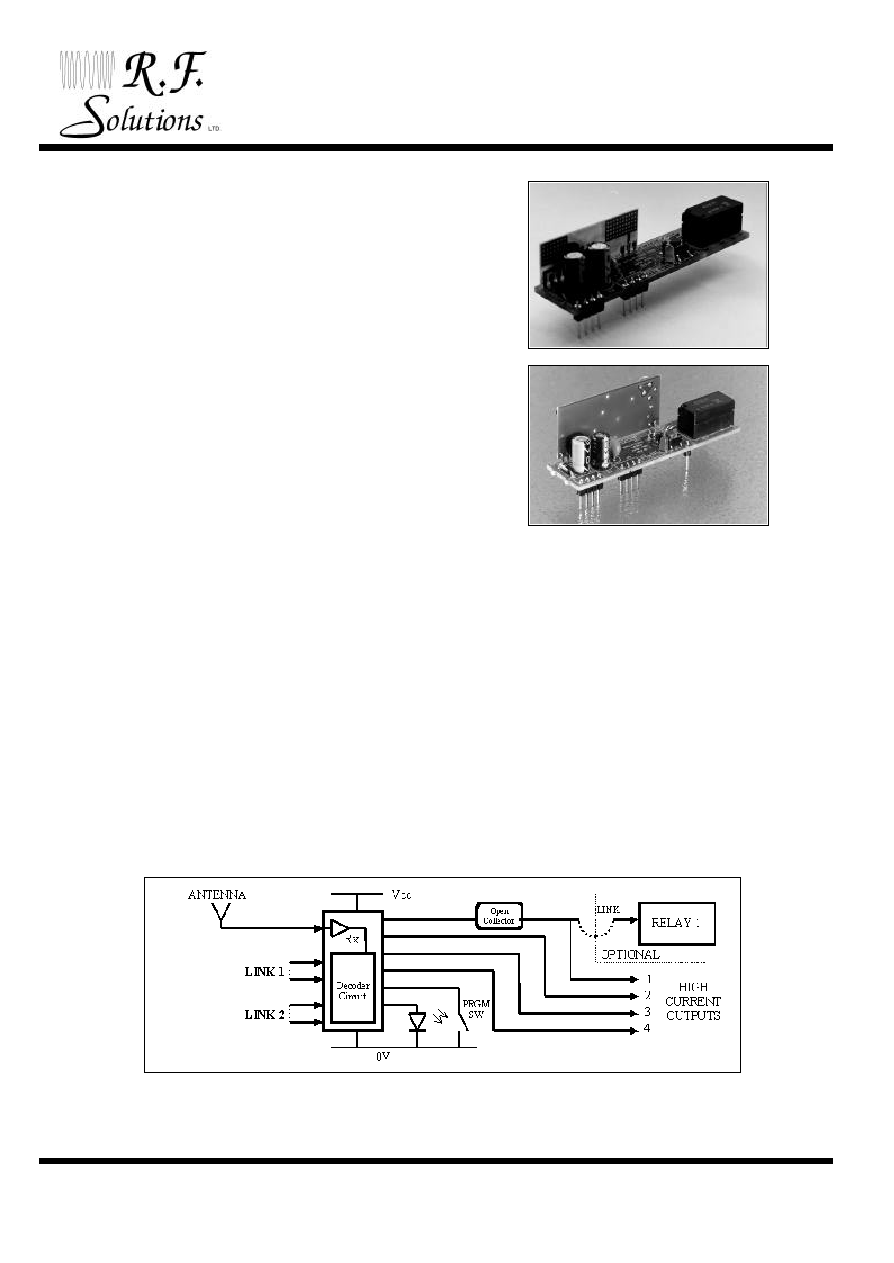
This range of miniature modules are complete four channel RF Receiver/Decoders that can be configured for
many different, low power, short range telemetry applications.
All modules are plug-in Dual-in-Line (DIL) package, with the same profile as a standard 40pin DIL I/C for easy
pcb mounting. A single relay option is an extended length module (removable) containing a BT/47 type relay.
Supplied as either AM or FM, the module requires connections to the power supply; 5Vdc or 12Vdc (mandatory
for relay version), and data outputs only. An LED indicates data reception.
Each decoder is compatible with one of the RF Solutions Transmitter / Encoders (see page 2). The decoder has
an easy-to-use 'LEARN' facility to allow the decoder to learn up to eight code Hopping or 16 standard
transmitter/encoders.
BLOCK DIAGRAM
FEATURES
∑
MINIATURE RF RECEIVER /DECODER.
∑
40 PIN DIP I/C PROFILE
∑
SINGLE RELAY OPTION AVAILABLE
∑
SUPPLIED AS AM OR FM COMPATIBLE.
∑
LED INDICATION OF DATA RECEPTION
∑
EASY LEARN TRANSMITTER FEATURE
∑
CMOS/TTL OUTPUTS, MOMENTARY OR
LATCHING.
∑
SINGLE SUPPLY EITHER 5V OR 12V
∑
LOW POWER CONSUMPTION RELAY
∑
CONTACTS 2A @ 12V
∑
AVAILABLE AS 418 OR 433MHz
∑
REQUIRES NO RADIO LICENCE
APPLICATIONS
∑
GENERAL REMOTE CONTROL SYSTEMS.
∑
GARAGE DOOR OPENERS.
∑
CAR, CARAVAN, MOTORCYCLE ALARMS
∑
REMOTE SWITCHING.
∑
REMOTE GATES.
∑
PAGING.
DS000011 Rev2.3 July `99
©
1999 REG No 277 4001, ENGLAND.
Page 2
M
INIATURE
RF R
ECEIVER
D
ECODER
M
ODULES
.
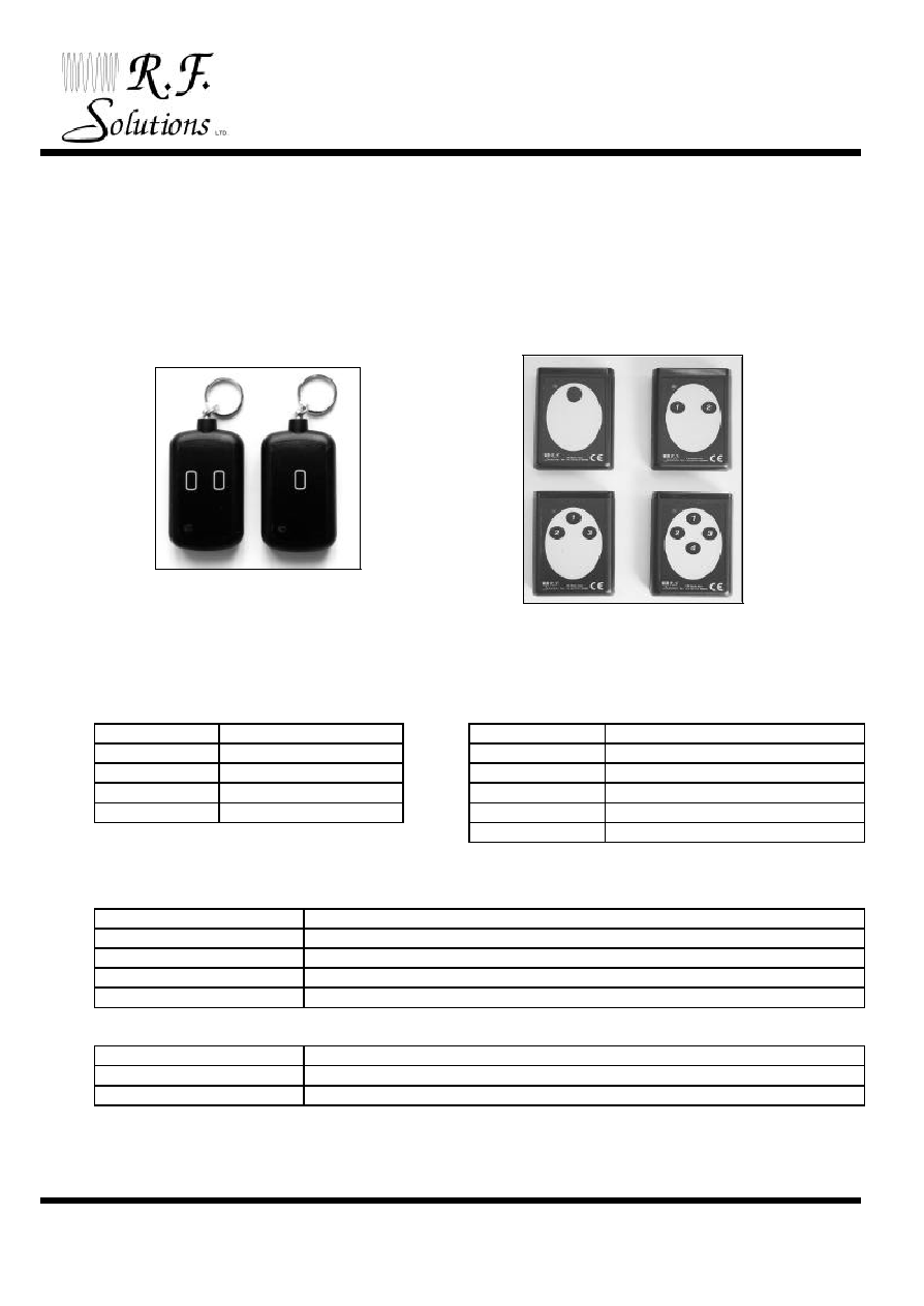
TRANSMITTER / ENCODER PART NUMBERING
Part No
Description
Part No
Description
AM-TS1-XXX
1 Switch (standard)
FM-EH4-XXX
Encoder 4 Switch PCB only
AM-TS2-XXX
2 Switch (standard)
FM-EH1C-XXX
Encoder 1 Switch in case
AM-TH1-XXX
1 Switch (hopping)
FM-EH2C-XXX
Encoder 2 Switch in case
AM-TH2-XXX
2 Switch (hopping)
FM-EH3C-XXX
Encoder 3 Switch in case
FM-EH4C-XXX
Encoder 4 Switch in case
DECODER PART NUMBERING
PART No
DESCRIPTION
AM-DS0(L)-XXX
AM Decoder - 1-3 Ch, Standard code, 40 Pin module
AM-DH0(L)-XXX
AM Decoder - 1-3 Ch, Hopping code, 40 Pin module
AM-DS1(L)-XXX
AM Decoder - 1-3 Ch, Standard code, module with Relay option
AM-DH1(L)-XXX
AM Decoder - 1-3 Ch, Hopping code, module with Relay option
PART No
DESCRIPTION
FM-DH0-XXX
FM Decoder - 1-4 Ch, Hopping code, 40 Pin module
FM-DH1-XXX
FM Decoder - 1-4 Ch, Hopping code, module with Relay option
L = AM-RRS2 Receiver ≠ Long Range XXX = 418 OR 433MHz
FEATURES OF FM VERSION
∑
RECEIVING RANGE UP TO 200 METRES.
∑
1 - 4 DATA CHANNELS
∑
LEARNS UP TO 8 OR 16 TRANSMITTERS
∑
HIGH SECURITY CODE HOPPING AVAILABLE
∑
SUPERHETRODYNE RF RECEIVER
∑
COMPATIBLE WITH RF SOLUTIONS FM
TRANSMITTERS/ENCODERS;
FEATURES OF AM VERSION
∑
RECEIVING RANGE 45 - 70 METRES.
∑
1 - 3 DATA CHANNELS
∑
LEARNS UP TO 8 OR 16 TRANSMITTERS
∑
HIGH SECURITY COPE HOPPING AVAILABLE
∑
COMPLIANT TO ETSI300-339
∑
COMPATIBLE WITH RF SOLUTIONS AM
TRANSMITTERS;

DS000011 Rev2.3 July `99
©
1999 REG No 277 4001, ENGLAND.
Page 3
M
INIATURE
RF R
ECEIVER
D
ECODER
M
ODULES
.
SIGNAL ALLOCATION (from plan view of module)
MECHANICAL DETAILS
P
P
S
S
W
W
1
1
9
9
.
.
0
0
5
5
m
m
m
m
+
+
/
/
-
-
0
0
.
.
2
2
5
5
3
3
.
.
3
3
4
4
m
m
m
m
+
+
/
/
-
-
0
0
.
.
2
2
C
C
O
O
M
M
P
P
O
O
N
N
E
E
N
N
T
T
S
S
S
S
I
I
D
D
E
E
P
P
I
I
N
N
S
S
O
O
N
N
0
0
.
.
1
1
"
"
P
P
I
I
T
T
C
C
H
H
P
P
I
I
N
N
S
S
A
A
R
R
E
E
D
D
I
I
A
A
1
1
m
m
m
m
R
R
E
E
L
L
A
A
Y
Y
A
A
M
M
R
R
X
X
F
F
M
M
R
R
X
X
1
1
.
.
9
9
m
m
m
m
+
+
/
/
-
-
0
0
.
.
1
1
F
F
R
R
O
O
M
M
E
E
D
D
G
G
E
E
O
O
F
F
P
P
C
C
B
B
T
T
O
O
P
P
C
C
B
B
L
L
O
O
C
C
A
A
T
T
I
I
N
N
G
G
H
H
O
O
L
L
E
E
S
S
1
1
7
7
5
5
.
.
5
5
7
7
m
m
m
m
+
+
/
/
-
-
0
0
.
.
2
2
R
R
X
X
M
M
O
O
D
D
U
U
L
L
E
E
1
1
5
5
m
m
m
m
(
(
A
A
M
M
)
)
2
2
3
3
m
m
m
m
(
(
F
F
M
M
)
)
L
L
E
E
D
D
2
2
.
.
5
5
4
4
m
m
m
m
1
1
4
4
0
0
2
2
3
3
9
9
3
3
3
3
8
8
4
4
3
3
7
7
3
3
6
6
3
3
5
5
3
3
4
4
8
8
3
3
3
3
9
9
3
3
2
2
1
1
0
0
3
3
1
1
1
1
1
1
3
3
0
0
1
1
2
2
2
2
9
9
1
1
3
3
2
2
8
8
1
1
4
4
2
2
7
7
1
1
5
5
2
2
6
6
1
1
6
6
2
2
5
5
1
1
7
7
2
2
4
4
1
1
8
8
2
2
3
3
1
1
9
9
2
2
2
2
2
2
0
0
2
2
1
1
P
P
4
4
/
/
3
3
P
P
4
4
/
/
2
2
P
P
4
4
/
/
1
1
+
+
1
1
2
2
V
V
0
0
V
V
+
+
5
5
V
V
0
0
V
V
O
O
/
/
P
P
1
1
O
O
/
/
P
P
2
2
O
O
/
/
P
P
3
3
O
O
/
/
P
P
4
4
L
L
I
I
N
N
K
K
2
2
L
L
I
I
N
N
K
K
2
2
L
L
I
I
N
N
K
K
1
1
L
L
I
I
N
N
K
K
1
1
+
+
v
v
e
e
L
L
E
E
D
D
P
P
S
S
W
W
1
1
N
N
/
/
C
C
P
P
S
S
W
W
1
1
N
N
/
/
C
C
P
P
I
I
N
N
S
S
3
3
6
6
-
-
3
3
9
9
,
,
2
2
2
2
-
-
2
2
3
3
U
U
S
S
E
E
D
D
B
B
Y
Y
F
F
M
M
R
R
X
X
2
2
M
M
O
O
D
D
U
U
L
L
E
E
O
O
N
N
L
L
Y
Y
A
A
N
N
T
T
E
E
N
N
N
N
A
A
I
I
/
/
P
P
R
R
E
E
L
L
A
A
Y
Y
C
C
O
O
N
N
T
T
A
A
C
C
T
T
S
S
N
N
O
O
R
R
M
M
A
A
L
L
L
L
Y
Y
C
C
L
L
O
O
S
S
E
E
D
D
C
C
O
O
M
M
M
M
O
O
N
N
N
N
O
O
R
R
M
M
A
A
L
L
L
L
Y
Y
O
O
P
P
E
E
N
N
N
N
O
O
T
T
U
U
S
S
E
E
D
D
C
C
K
K
1
1
C
C
K
K
2
2
B
B
R
R
E
E
A
A
K
K
H
H
E
E
R
R
E
E
I
I
F
F
R
R
E
E
L
L
A
A
Y
Y
N
N
O
O
T
T
R
R
E
E
Q
Q
U
U
I
I
R
R
E
E
D
D
P
P
I
I
N
N
S
S
2
2
6
6
-
-
2
2
8
8
,
,
3
3
2
2
,
,
3
3
5
5
-
-
4
4
0
0
U
U
S
S
E
E
D
D
B
B
Y
Y
A
A
M
M
R
R
X
X
2
2
/
/
R
R
R
R
S
S
2
2
M
M
O
O
D
D
U
U
L
L
E
E
O
O
N
N
L
L
Y
Y
R
R
L
L
Y
Y
N
N
/
/
C
C
N
N
/
/
C
C
N
N
/
/
C
C
N
N
/
/
C
C
N
N
/
/
C
C
N
N
/
/
C
C

DS000011 Rev2.3 July `99
©
1999 REG No 277 4001, ENGLAND.
Page 4
M
INIATURE
RF R
ECEIVER
D
ECODER
M
ODULES
.
PIN DESCRIPTION
Pin No
Name
Description
1
+12V
+12V Supply Voltage. Must be used for Relay operation
2
0 VOLT
Ground for +12V Supply.
3
+5V
+5V Supply Voltage. Alternative supply if 12v supply not used.
4
0 VOLT
Ground for +5V Supply.
8
O/P1
Data output channel 1. Open collector Transistor output.
(This is used to drive the relay when fitted)
9
O/P2
Data output channel 2. CMOS/TTL with series 220
resistor
10
O/P3
Data output channel 3. CMOS/TTL with series 220
resistor
11
O/P4
Data output channel 4. CMOS/TTL with series 220
resistor
12
LINK2
Connect to pin 13 to make "Link2"
13
LINK2
Connect to pin 12 to make "Link2"
14
LINK1
Connect to pin 15 to make "Link1"
15
LINK1
Connect to pin 14 to make "Link1"
16
+ve LED
External LED sink output, can be connected directly to cathode of external LED.
Connect Anode of the LED to +5V.
Indicates Data reception, and programming status.
17
PSW1
Programming Switch, This is used when learning new transmitters.
18
N/C
Not connected. Can be used as locating pin for mounting the module
19
PSW1
Connect to 17 to make "PSW1" switch.
20
N/C
Not connected. Can be used as locating pin for mounting the module
21
ANT I/P
Connect Antenna to this input
22 - 23
These pins are used by the module when configured as FM.
24 - 25
N/C
Not connected. Can be used as locating pin for mounting the module
26 - 28
These pins are used by the module when configured as AM.
29 - 31
N/C
Not connected. Can be used as locating pin for mounting the module
32
These pins are used by the module when configured as AM.
33 - 34
N/C
Not connected. Can be used as locating pin for mounting the module
35
These pins are used by the module when configured as AM.
36 - 40
These pins are used when configured as an AM or FM module.
P4/1
P4/1
Relay contacts Normally Open
P4/2
P4/2
Relay contacts Common
P4/3
P4/3
Relay contacts Normally Closed
NOTE
The module is designed to be powered from either 12v or 5v not both!
The 12v supply is necessary for relay operation.
Removal of Relay
If the relay is not required, remove the relay connecting links "CK1" & "CK2" . The pcb may then be carefully
broken, along the score lines between the relay and the rest of the board. Digital output channel 1 is then
driven by an open collector transistor output.

DS000011 Rev2.3 July `99
©
1999 REG No 277 4001, ENGLAND.
Page 5
M
INIATURE
RF R
ECEIVER
D
ECODER
M
ODULES
.
"STANDARD DATA FORMAT" DESCRIPTION (AM-DS0, AM-DS1)
The transmitter/encoders used in a standard system each have a unique signature code (pre-programmed at
manufacture) from one in >16,000,000 combinations. Error checking techniques are also used to ensure data
integrity.
These decoders are capable of learning 16 unique transmitter/Encoder signature codes.
"HOPPING DATA FORMAT" DESCRIPTION (AM-DH0, AM-DH1, FM-DH0, FM-DH1)
The transmitter/encoders used in a Code Hopping system each have a random number signature code, as in
the standard format, and also transmit a unique signature code each time the switch is pressed. The number
of possible codes is >16,000,000 combinations, the same code is never repeated, even if the batteries are
changed.. Error checking techniques are also used to ensure data integrity.
These decoders are capable of learning 8 unique transmitter/Encoder signature codes.
LEARNING A NEW TRANSMITTER
1. Hold down the programming switch (PSW1).
2. Depress the transmitter once, LED on the decoder will flash. (PSW1 is still depressed).
3. Wait for LED to stop flashing.
4. Depress the transmitter again, LED will turn off. (PSW1 is still depressed).
5. Release the programming switch (PSW1).
6. This transmitter will now operate the system.
7. To completely erase the transmitters, press PSW1 on the decoder five times in succession, LED will
remain on for approximately 5 seconds while the transmitter(s) are being erased.
SYNCHRONISATION (Hopping Models only)
This equipment requires the transmitter and receiver to be synchronised. If the transmitter has been pressed
more than 50 times outside the range of the receiver, the receiver will loose synchronisation with the
transmitter. To re-synchronise:
Press the transmitter key for two seconds within range of the receiver,
Release the key momentarily, and press the key again.
ANTENNA DESIGN
For 99% of applications a 16.5cm piece of wire is quite adequate. The range achieved from the system is
dependant on the choice and position of the antenna. The space around the antenna is as important as the
antenna itself. The optimum position is to locate the antenna so that is protrudes directly out the top of the
transmitter box. If this is not possible due to other design constraints, try to keep the antenna away from
other metal in the system such as transformers, batteries and PCB tracks, especially ground planes. In
particular, the `HOT' end of the antenna should be kept as far away as possible from these.
For further information on Antenna design please see our full product catalogue.
DATA OUTPUTS
Output 1 is used to drive the on-board relay (if fitted), it is an open collector type output.
Outputs 2,3 & 4 are digital CMOS/TTL with a series 220 W protection resistor
The outputs are configured by Link 1 & 2
DS000011 Rev2.3 July `99
©
1999 REG No 277 4001, ENGLAND.
Page 6
M
INIATURE
RF R
ECEIVER
D
ECODER
M
ODULES
.
AM DECODER WITH 1 SWITCH AM TRANSMITTER
LINK1
LINK2
O/P 1
O/P 2
OPEN
OPEN
LATCH
LATCH
OPEN
CONNECTED
MOM
MOM
CONNECTED
OPEN
LATCH
MOM
CONNECTED
CONNECTED
MOM
LATCH
AM DECODER WITH A 2 SWITCH AM TRANSMITTER
LINK STATUS
TRANSMITTER SWITCH
ANY
RH
LH
BOTH
LINK1
LINK2
O/P 1
O/P 2
O/P 3
O/P 4
OPEN
OPEN
LATCH
LATCH
LATCH
LATCH
OPEN
CONNECTED
MOM
MOM
MOM
MOM
CONNECTED
OPEN
LATCH
MOM
LATCH
LATCH
CONNECTED
CONNECTED
MOM
LATCH
MOM
MOM
FM DECODER WITH A 4 SWITCH FM TRANSMITTER
LINK1
LINK2
O/P 1
O/P 2
O/P 3
O/P 4
OPEN
OPEN
LATCH
LATCH
LATCH
LATCH
OPEN
CONNECTED
MOM
MOM
MOM
MOM
CONNECTED
OPEN
MOM
MOM
LATCH
LATCH
CONNECTED
CONNECTED
LATCH
LATCH
MOM
MOM

DS000011 Rev2.3 July `99
©
1999 REG No 277 4001, ENGLAND.
Page 7
M
INIATURE
RF R
ECEIVER
D
ECODER
M
ODULES
.
ABSOLUTE MAXIMUM RATINGS (AM & FM)
Supply Voltage (+12Vcc to GND)........................................-0.3 to +17 Volts.
Supply Voltage (+5Vcc to GND)..........................................-0.3 to + 6 Volts.
Storage Temperature..........................................................-30 to +85o Celsius.
Operating Temperature....................................................... 0 to +55o Celsius.
TECHNICAL SPECIFICATION (AM & FM)
Ambient temperature
= 25
o
Celsius.
ELECTRICAL CHARACTERISTICS
MIN
TYPICAL
MAX
DIMENSION
NOTE
Supply Voltage for +12 v
9
12.0
16.0
V
SINGLE
Supply Voltage for +5 v
4.5
5.0
5.5
V
SUPPLY ONLY!
Data output: (Ch 2, 3, & 4)
Logic Low
0
0.2
0.8
V
I out = 10mA
Logic High
3.5
3.8
5
V
I out = 10mA
Data output: (Ch 2, 3, & 4)
Logic Low
-25
mA
Logic High
20
mA
Data output :Ch 1 (open collector)
50
mA
Relay removed
Relay Rating
2
A
@ 12 V DC
ELECTRICAL CHARACTERISTICS UNIQUE TO AM DECODERS
ELECTRICAL CHARACTERISTICS
MIN
TYPICAL
MAX
UNIT
Operating Temperature Range
0
70
V
Supply Current (quiescent)
10
mA
Supply Current (operating relay)
50
70
mA
Working Frequency
200
450
MHz
Tuning Tolerance
+/- 0.2
+/- 0.5
MHz
-3dB Bandwidth
+/- 2
+/- 3
MHz
R.F Sensitivity (100% AM)
-100
-105
dBm
Level of Emitted Spectrum
-65
-60
dBm
EMC Compliance
Complies to ETS300-339
ELECTRICAL CHARACTERISTICS UNIQUE TO FM DECODERS
ELECTRICAL CHARACTERISTICS
MIN
TYPICAL
MAX
UNIT
Supply Current (quiescent)
20
mA
Supply Current (operating relay)
40
75
mA
Overall Frequency Accuracy
-100
0
+100
KHz
Sensitivity for 20dB S/N
-
0.5
1.0
µ
V
IF Bandwidth
250
KHz
For more information or general enquiries, please call;
R. F. Solutions Ltd,
Unit 21, Cliffe Industrial Estate,
South Street,
Lewes,
E Sussex. BN8 6JL.
England.
Tel +44 (0)1273 898 000
Fax +44 (0)1273 480 661.
Web Page : http://www.rfsolutions.co.uk
Email :sales@rfsolutions.co.uk
RF Solutions is a member of the Low Power Radio Association.
Information contained in this document is believed to be accurate , however no representation or warranty is given and no liability is assumed by R.F. Solutions Ltd. with respect to the accuracy of such
information. Use of R.F.Solutions as critical components in life support systems is not authorised except with express written approval from R.F.Solutions Ltd.