ChipFind - документация

Электронный компонент: CY7C1427AV18

Скачать:  PDF   ZIP
www.docs.chipfind.ru
background image
PRELIMINARY
36-Mbit DDR-II SRAM 2-Word
Burst Architecture
CY7C1416AV18
CY7C1427AV18
CY7C1418AV18
CY7C1420AV18
Cypress Semiconductor Corporation
3901 North First Street
San Jose
,
CA 95134
408-943-2600
Document Number: 38-05616 Rev. **
Revised July 15, 2004
Features
36-Mbit density (4M x 8, 4M x 9, 2M x 18, 1M x 36)
250-MHz clock for high bandwidth
2-Word burst for reducing address bus frequency
Double Data Rate (DDR) interfaces
(data transferred at 500 MHz) @ 250 MHz
Two input clocks (K and K) for precise DDR timing
-- SRAM uses rising edges only
Two output clocks (C and C) account for clock skew
and flight time mismatching
Echo clocks (CQ and CQ) simplify data capture in
high-speed systems
Synchronous internally self-timed writes
1.8V core power supply with HSTL inputs and outputs
Variable drive HSTL output buffers
Expanded HSTL output voltage (1.4VV
DD
)
15 x 17 x 1.4 mm 1.0-mm pitch fBGA package,
165 ball (11x15 matrix)
JTAG 1149.1 compatible test access port
Delay Lock Loop (DLL) for accurate data placement
Configurations
CY7C1416AV18 4M x 8
CY7C1427AV18 4M x 9
CY7C1418AV18 2M x 18
CY7C1420AV18 1M x 36
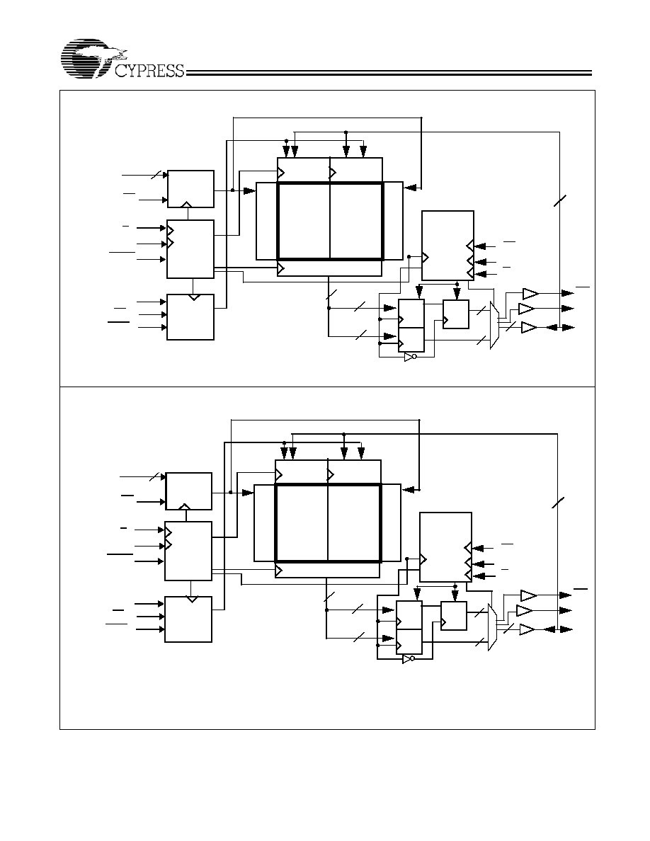
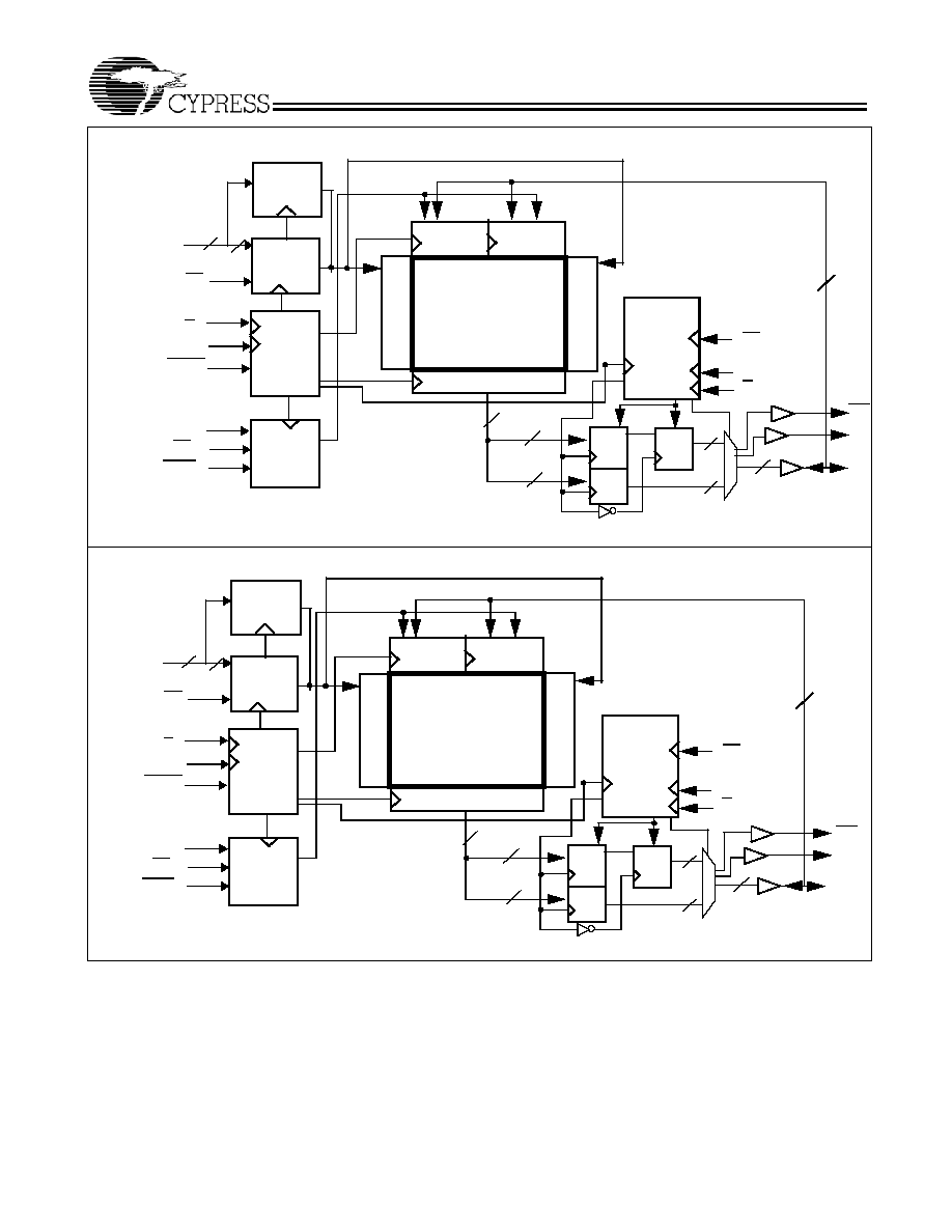
Functional Description
The CY7C1416AV18, CY7C1427AV18, CY7C1418AV18, and
CY7C1420AV18 are 1.8V Synchronous Pipelined SRAM
equipped with DDR-II architecture. The DDR-II consists of an
SRAM core with advanced synchronous peripheral circuitry
and a 1-bit burst counter. Addresses for Read and Write are
latched on alternate rising edges of the input (K) clock. Write
data is registered on the rising edges of both K and K. Read
data is driven on the rising edges of C and C if provided, or on
the rising edge of K and K if C/C are not provided. Each
address location is associated with two 8-bit words in the case
of CY7C1416AV18 and two 9-bit words in the case of
CY7C1427AV18 that burst sequentially into or out of the
device. The burst counter always starts with a "0" internally in
the case of CY7C1416AV18 and CY7C1427AV18. On
CY7C1418AV18 and CY7C1420AV18, the burst counter takes
in the least significant bit of the external address and bursts
two 18-bit words in the case of CY7C1418AV18 and two 36-bit
words in the case of CY7C1420AV18 sequentially into or out
of the device.
Asynchronous inputs include impedance match (ZQ).
Synchronous data outputs (Q, sharing the same physical pins
as the data inputs D) are tightly matched to the two output echo
clocks CQ/CQ, eliminating the need for separately capturing
data from each individual DDR SRAM in the system design.
Output data clocks (C/C) enable maximum system clocking
and data synchronization flexibility.
All synchronous inputs pass through input registers controlled
by the K or K input clocks. All data outputs pass through output
registers controlled by the C or C input clocks. Writes are
conducted with on-chip synchronous self-timed write circuitry.
Selection Guide
250 MHz
200 MHz
167 MHz
Unit
Maximum Operating Frequency
250
200
167
MHz
Maximum Operating Current
TBD
TBD
TBD
mA
Shaded areas contain advance information.
background image
PRELIMINARY
CY7C1416AV18
CY7C1427AV18
CY7C1418AV18
CY7C1420AV18
Document Number: 38-05616 Rev. **
Page 2 of 24
Logic Block Diagram (CY7C1416AV18)
CLK
A
(20:0)
Gen.
K
K
Control
Logic
Address
Register
Re
ad Ad
d.

Dec
ode
Read Data Reg.
R/W
DQ
[7:0]
Output
Logic
Reg.
Reg.
Reg.
8
8
16
8
NWS
[1:0]
V
REF
W
r
i
t
e A
d
d
.
De
co
de
8
C
C
8
LD
Control
21
2M
x 8 Array
2M
x 8
Ar
ray
Write
Reg
Write
Reg
CQ
CQ
R/W
DOFF
Logic Block Diagram (CY7C1427AV18)
CLK
A
(20:0)
Gen.
K
K
Control
Logic
Address
Register
R
e
ad
A
d
d.
De
c
o
d
e
Read Data Reg.
R/W
DQ
[8:0]
Output
Logic
Reg.
Reg.
Reg.
9
9
18
9
BWS
[0]
V
REF
W
r
ite Ad
d
.
D
e
c
o
de
9
C
C
9
LD
Control
21
2M
x 9 Array
2M
x 9 Array
Write
Reg
Write
Reg
CQ
CQ
R/W
DOFF
background image
PRELIMINARY
CY7C1416AV18
CY7C1427AV18
CY7C1418AV18
CY7C1420AV18
Document Number: 38-05616 Rev. **
Page 3 of 24
2M x 18 Array
Write
Reg
Write
Reg
Logic Block Diagram (CY7C1418AV18)
CLK
A
(20:0)
Gen.
K
K
Control
Logic
Address
Register
Re
ad
Ad
d. D
e
c
o
d
e
Read Data Reg.
R/W
DQ
[17:0]
Output
Logic
Reg.
Reg.
Reg.
18
18
36
18
BWS
[1:0]
V
REF
W
r
ite A
d
d
.

D
e
co
de
18
21
C
C
18
LD
Control
Burst
Logic
A0
A
(20:1)
20
CQ
CQ
R/W
DOFF
Logic Block Diagram (CY7C1420AV18)
CLK
A
(19:0)
Gen.
K
K
Control
Logic
Address
Register
R
e
ad
Ad
d. De
c
o
d
e
Read Data Reg.
R/W
DQ
[35:0]
Output
Logic
Reg.
Reg.
Reg.
36
36
72
36
BWS
[3:0]
V
REF
W
r
ite A
d
d
.
D
e
c
o
de
36
20
C
C
36
LD
Control
Burst
Logic
A0
A
(19:1)
19
1M x 36 Array
Write
Reg
Write
Reg
CQ
CQ
36
R/W
DOFF
background image
PRELIMINARY
CY7C1416AV18
CY7C1427AV18
CY7C1418AV18
CY7C1420AV18
Document Number: 38-05616 Rev. **
Page 4 of 24
Pin Configurations
CY7C1416AV18 (4M 8) 15 17 FBGA
2
3
4
5
6
7
1
A
B
C
D
E
F
G
H
J
K
L
M
N
P
R
A
CQ
NC
NC
NC
NC
DOFF
NC
NC/72M
A
NWS
1
K
R/W
NC/144M
NC
NC
NC
NC
NC
TDO
NC
NC
NC
NC
NC
NC
TCK
NC
NC
A NC/288M
K
NWS
0
V
SS
A
A
A
NC
V
SS
V
SS
V
SS
V
SS
V
DD
A
V
SS
V
SS
V
SS
V
DD
DQ4
NC
V
DDQ
NC
NC
NC
NC
DQ7
A
V
DDQ
V
SS
V
DDQ
V
DD
V
DD
DQ5
V
DDQ
V
DD
V
DDQ
V
DD
V
DDQ
V
DD
V
SS
V
DD
V
DDQ
V
DDQ
V
SS
V
SS
V
SS
V
SS
A
A
C
V
SS
A
A
A
NC
V
SS
NC
V
SS
NC
NC
V
REF
V
SS
V
DD
V
SS
V
SS
A
V
SS
C
NC
DQ6
NC
NC
NC
V
DD
A
8
9
10
11
NC
A
A
LD
CQ
A NC
NC
DQ3
V
SS
NC
NC
NC
NC
V
SS
NC
DQ2
NC
NC
NC
V
REF
NC
NC
V
DDQ
NC
V
DDQ
NC
NC
V
DDQ
V
DDQ
V
DDQ
NC
V
DDQ
NC
DQ1
NC
V
DDQ
V
DDQ
NC
V
SS
NC
NC
NC
TDI
TMS
V
SS
A
NC
A
NC
NC
NC
ZQ
NC
DQ0
NC
NC
NC
NC
A
CY7C1427AV18 (4M 9) 15 17 FBGA
2
3
4
5
6
7
1
A
B
C
D
E
F
G
H
J
K
L
M
N
P
R
A
CQ
NC
NC
NC
NC
DOFF
NC
NC/72M
A
NC
K
R/W
NC/144M
NC
NC
NC
NC
NC
TDO
NC
NC
NC
NC
NC
NC
TCK
NC
NC
A NC/288M
K
BWS
0
V
SS
A
A
A
NC
V
SS
V
SS
V
SS
V
SS
V
DD
A
V
SS
V
SS
V
SS
V
DD
DQ4
NC
V
DDQ
NC
NC
NC
NC
DQ7
A
V
DDQ
V
SS
V
DDQ
V
DD
V
DD
DQ5
V
DDQ
V
DD
V
DDQ
V
DD
V
DDQ
V
DD
V
SS
V
DD
V
DDQ
V
DDQ
V
SS
V
SS
V
SS
V
SS
A
A
C
V
SS
A
A
A
NC
V
SS
NC
V
SS
NC
NC
V
REF
V
SS
V
DD
V
SS
V
SS
A
V
SS
C
NC
DQ6
NC
NC
NC
V
DD
A
8
9
10
11
DQ8
A
A
LD
CQ
A NC
NC
DQ3
V
SS
NC
NC
NC
NC
V
SS
NC
DQ2
NC
NC
NC
V
REF
NC
NC
V
DDQ
NC
V
DDQ
NC
NC
V
DDQ
V
DDQ
V
DDQ
NC
V
DDQ
NC
DQ1
NC
V
DDQ
V
DDQ
NC
V
SS
NC
NC
NC
TDI
TMS
V
SS
A
NC
A
NC
NC
NC
ZQ
NC
DQ0
NC
NC
NC
NC
A
background image
PRELIMINARY
CY7C1416AV18
CY7C1427AV18
CY7C1418AV18
CY7C1420AV18
Document Number: 38-05616 Rev. **
Page 5 of 24
Pin Configurations
(continued)
CY7C1418AV18 (2M 18) 15 17 FBGA
2
3
4
5
6
7
1
A
B
C
D
E
F
G
H
J
K
L
M
N
P
R
A
CQ
NC
NC
NC
NC
DOFF
NC
NC/72M
A
BWS
1
K
R/W
NC/144M
DQ9
NC
NC
NC
NC
TDO
NC
NC
NC
NC
NC
NC
TCK
NC
NC
A NC/288M
K
BWS
0
V
SS
A
A0
A
DQ10
V
SS
V
SS
V
SS
V
SS
V
DD
A
V
SS
V
SS
V
SS
V
DD
DQ11
NC
V
DDQ
NC
DQ14
NC
DQ16
DQ17
A
V
DDQ
V
SS
V
DDQ
V
DD
V
DD
DQ13
V
DDQ
V
DD
V
DDQ
V
DD
V
DDQ
V
DD
V
SS
V
DD
V
DDQ
V
DDQ
V
SS
V
SS
V
SS
V
SS
A
A
C
V
SS
A
A
A
NC
V
SS
NC
V
SS
DQ12
NC
V
REF
V
SS
V
DD
V
SS
V
SS
A
V
SS
C
NC
DQ15
NC
NC
NC
V
DD
A
8
9
10
11
DQ0
A
A
LD
CQ
A NC
NC
DQ8
V
SS
NC
DQ7
NC
NC
V
SS
NC
DQ6
NC
NC
NC
V
REF
NC
DQ3
V
DDQ
NC
V
DDQ
NC
DQ5
V
DDQ
V
DDQ
V
DDQ
NC
V
DDQ
NC
DQ4
NC
V
DDQ
V
DDQ
NC
V
SS
NC
NC
NC
TDI
TMS
V
SS
A
NC
A
NC
NC
NC
ZQ
NC
DQ2
NC
DQ1
NC
NC
A
2
3
4
5
6
7
1
A
B
C
D
E
F
G
H
J
K
L
M
N
P
R
A
CQ
NC
NC
NC
NC
DOFF
NC
NC/144M
A
BWS
2
K
R/W
BWS
1
DQ27
DQ18
NC
NC
NC
TDO
NC
NC
DQ31
NC
NC
NC
TCK
NC
DQ28
A BWS
3
K
BWS
0
V
SS
A
A0
A
DQ19
V
SS
V
SS
V
SS
V
SS
V
DD
A
V
SS
V
SS
V
SS
V
DD
DQ20
DQ21
V
DDQ
DQ32
DQ23
DQ34
DQ25
DQ26
A
V
DDQ
V
SS
V
DDQ
V
DD
V
DD
DQ22
V
DDQ
V
DD
V
DDQ
V
DD
V
DDQ
V
DD
V
SS
V
DD
V
DDQ
V
DDQ
V
SS
V
SS
V
SS
V
SS
A
A
C
V
SS
A
A
A
DQ29
V
SS
NC
V
SS
DQ30
NC
V
REF
V
SS
V
DD
V
SS
V
SS
A
V
SS
C
NC
DQ33
NC
DQ35
DQ24
V
DD
A
8
9
10
11
DQ0
A
NC/72M
LD
CQ
A NC
NC
DQ8
V
SS
NC
DQ17
DQ7
NC
V
SS
NC
DQ6
DQ14
NC
NC
V
REF
NC
DQ3
V
DDQ
NC
V
DDQ
NC
DQ5
V
DDQ
V
DDQ
V
DDQ
DQ4
V
DDQ
NC
DQ13
NC
V
DDQ
V
DDQ
NC
V
SS
NC
DQ1
NC
TDI
TMS
V
SS
A
NC
A
DQ16
DQ15
NC
ZQ
DQ12
DQ2
DQ10
DQ11
DQ9
NC
A
CY7C1420AV18 (1M 36) 15 17 FBGA