 | –≠–ª–µ–∫—Ç—Ä–æ–Ω–Ω—ã–π –∫–æ–º–ø–æ–Ω–µ–Ω—Ç: DS1410E | –°–∫–∞—á–∞—Ç—å:  PDF PDF  ZIP ZIP |

1 of 7
021798
FEATURES
ß
Provides a parallel port interface for Dallas iButtons
ß
Compatible with low-power parallel ports
ß
No external power required
ß
Operates with DOS, Windows, Windows 95, Windows
NT, SCO UNIX, UNIXWARE, and HP_UX for
workstations
DESCRIPTION
The DS1410E Parallel Port Adapter interfaces Dallas Semiconductor Authorization iButtons to host
computers via a PC parallel port. In conjunction with the iButton, the DS1410E provides a high security
storage vault for critical execution control information. Only users who posses an iButton can utilize the
software, preventing execution of unauthorized copies.
The modularity of the DS1994 allows for easy feature customization. The device supports the insertion of
two iButtons, which can be removed and replaced to vary functionality.
For example, a DS1994 Time iButton can be programmed for a 30-day expiration, issued with a
DS1410E and a software copy. The evaluator can be converted into a registered user by issuing a DS1991
Multi iButton and inserting it into the second receptacle. The DS1410E supports the same iButtons as
other Dallas port adapters. This allows standardization of any protection scheme across virtually all
hardware platforms, regardless of the operating system. The iButtons remain constant, and the port
adapters change according to the specific platform interface.
DS1410E SOFTWARE
The DS1410k Development Kit contains access system software which must be linked with the
application software in order to complete integration. The support for the application development
environments and operating systems lies in the interface software of the access system. The access system
contains the low-level interface for communicating with the iButtons.
OPERATION
The DS1410E utilizes a DS1481 1-Wire
TM
Bus Master to communicate with iButtons. The DS1481
generates either a read/write bit "time slot" or a reset on the I/O pin (1-Wire bus). The operation
performed is determined by the states of input pins 2 and 3 on the port adapter as follows:
TIME SLOT
PIN 2
PIN 3
Read 0, Read1, Write 1
logic high
logic high(see Figure 1)
Write 0
logic low
logic high (see Figure 2)
1-Write Reset
logic high
logic low (See Figure 3)
DS1410E
Parallel Port Adapter
www.dalsemi.com

DS1410E
2 of 7
021798
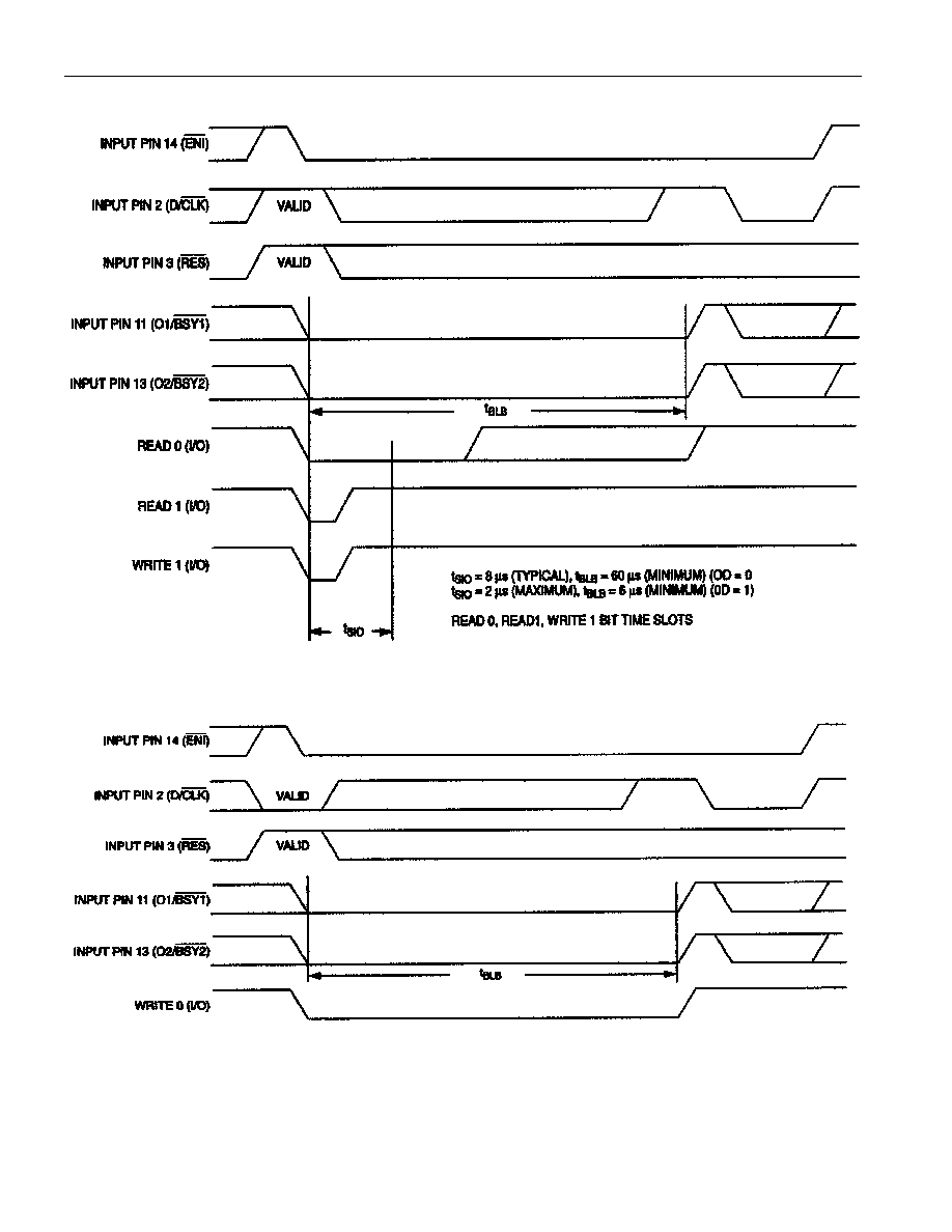
After input pins 2 and 3 have been set, the time slot begins by driving input pin 14 to its active state
(low). A falling edge on input pin 14 causes the DS1481 to drive input pins 11 and 13 low (indicating a
time slot is in progress).
While input pins 11 and 13 are low, the host processor is free to perform other tasks (including running
the print spooler). When the time slot is complete input pins 11 and 13 are restored to the states of output
pins 11and 13.
When the host detects that one or both of the busy signals has returned high, it must query the result of
the time slot. This is accomplished by driving input pin 2 low. If the 1-Wire bus was low (read 0, write 0,
or presence detect) the DS1481 drives both input pins 11 and 13 low (this state was held until input pins
14 or 2 return high). Otherwise it propagates the states of output pins 11 and 13.
After the host reads the time slot result it must drive input pin 14 to its inactive state (high). The DS1481
will then set input pins 11 and 13 to the state of output pins 11 and 13.
DS1410E 1-WIRE TIMING GENERATION
For all time slots, the DS1481 samples the I/O pin at t
SIO
(see Figure 3). The DS1481 waits a minimum of
60
µ
s from the start of the time slot and de-asserts input pins 11 and 13.
When a reset is requested, the DS1481 drives the I/O pin low for at least 480
µ
s and then releases it.
During a normal reset the I/O pin immediately begins to return high.
If a 1-Wire device is present on the I/O line it pulls I/O low after time T (15
µ
s
T
60
µ
s) from the
previous rising edge. The 1-Wire device(s) holds the I/O line low for 4T and then releases it, allowing the
I/O line to return high. This is the presence detect pulse. The I/O line must remain high (in its idle state)
for at least 3T before the 1-Wire device(s) is ready for further communication. To insure this idle high
time is satisfied, the DS1481 does not release input pins 11 and 13 for at least 960
µ
s (measured from the
1
st
falling edge on the I/O pin).
If after 480
µ
s of low time the I/O line did not return high, either the I/O line has been shorted to ground
or there is at least one 1-Wire device connected to the I/O line which is issuing an alarm interrupt (see
Figure 3). In this case the DS1481 waits for I/O to return high for an additional 3840
µ
s (64 * 60). If time
expires the I/O line is assumed to be shorted and the DS1481 releases input pins 11 and 13. If the I/O line
returns high, the DS1481 continues to monitor the presence detect portion of the reset (as described
above) as for the non-interrupt case. Note that the 3T idle high time is still required after the presence
detect ends.
OVERDRIVE
The DS1481 also supports overdrive communication with overdrive capable 1-Wire devices. When the
DS1481 powers up it is in normal mode (i.e., OD = 0, Figure 1). To toggle to overdrive mode the host
sets input pins 2 and 3 low and drives Input pin 14 low. The DS1481 toggles the OD (OverDrive) bit to a
logic high and returns the states of output pins 11 and 13 on input pins 11 and 13. Overdrive mode is
cleared in the same way. When Overdrive is turned off (OD = 0). Input pins 11 and 13 are driven low to
report the state of the OD bit.
When OD = 1, communication with the 1-Wire devices is exactly as described in the operation section
above. The actual 1-Wire timing for both modes of operation is described in figures 1, 2 and 3 below.
Note that when toggling the OD bit there is no change on the I/O line.

DS1410E
3 of 7
021798
PRINTER COEXISTENCE
In order to coexist with parallel port printers, the DS1410E utilizes output pins 11 and 13 and input pins
11 and 13. When input pin 14 is low these pins are used for transmitting data received on the I/O pin or
for issuing an unmistakable busy signal. When input pin 14 is inactive (high) input pins 11 and 13
propagate the states of output pins 11 and 13.
If a printer is attached to a DS1410E, output pin 11 is connected to the printers BUSY signal (low only if
printer is on-line and busy), and output pin 13 is connected to SELECT OUT (driven low if printer is off-
line), see Figure 2.
If the attached printer is "powered up" and on-line, the DS1410E uses SELECT OUT for communication
regardless of the state of the printers BUSY signal. If the printer is offline its BUSY signal is inactive
(high) and this line is used by the DS1410E for host communication.
If the attached printer is powered off, both SELECT OUT and BUSY will be low. This prevents
meaningful communication with the DS1410E because it is unable to de-assert its busy signal (input pins
11 and 13 low) or return a high sample of the I/O pin.
To solve this problem, the DS1481 uses the busy signal issued during a reset to detect the presence of
another DS1481 based device attached behind it on the parallel port. If this busy signal is not detected by
the DS1481, it assumes that it is the last DS1481 based device on the port.
If the DS1410E determines that it is the last device on the port it ignores the states of output pins 11 and
13 while input pin 14 is low. It also leaves the output pin 14 high to prevent sending line feed signals to
the printer. This gives the last device the ability to control input pins 11 and 13 without affecting
stackability.
DS1410E
4 of 7
021798
HOST INTERFACE TIMING DIAGRAMS
Figure 1
HOST INTERFACE TIMING DIAGRAMS Figure 2 (cont'd)
t
BLB
= 60
µ
s (MINIMUM) (OD=0)
t
BLB
= 6
µ
s (MINIMUM) (OD=1)
WRITE 0 TIME SLOTS

DS1410E
5 of 7
021798
HOST INTERFACE TIMING DIAGRAMS Figure 3 (cont'd)
t
PDH
= 2
µ
s (TYPICAL)
t
BLR
= 960
µ
s (MINIMUM) (OD = 0
t
BLB
= 96
µ
s (MINIMUM) (OD = 1)
1- WIRE RESET
PIN
I/O
DESCRIPTION
Input pin
14
( EN I
)
I
Chip enable, driven low to begin 1-Wire I/O.
Input pin 11
(O1/
BSY1
)
O
Driven low during time slot (to indicate a DS1481 busy condition). Set to state
of I1 after time slot has finished. (O1/
BSY1
) will go low after D/
CLK
goes low
if sample of I/O communication was low. Returns to state I1 when
ENI
goes
back high (see Figure).
Input pin 13
(O2/
BSY2
)
O
Driven low during time slot (to indicate a DS1481 busy condition). Set to state
of 12 after time slot has finished. O2/
BSY2
will go low after D/
CLK
goes low
if sample of I/O communication was low. Returns to state of 12 when
ENI
goes back high (see Figure).
Input pin 2
(
D/ CLK )
I
Data/Clock pin. Used to specify type of time slot before communication
begins. After the time slot has been completed this pin is driven low in order to
solicit the result of the time slot.
Input pin 3
(
RES
)
I
Set low (before
ENI
is driven low) to specify that a reset pulse should be
generated on the I/O pin.
Output Pin 11
(I1)
I
Can be connected to the O1/
BSY1
of another DS1481. May also be connected
to a parallel port printer's BUSY signal. Internally pulled high via a weak
resistor.
Output Pin 13
(I2)
I
Can be connected to the O2/
BSY2
of another DS1481. Can also be connected
to a parallel port printer SELECT OUT signal. Internally pulled high via a
weak resistor
Output Pin 14
(
ENO
)
O
Set to
ENI
if not the last part on port. Open drain output with weak internal
pullup resistor.
I/O
I/O
1-Wire I/O line. Bi-directional line with open drain output.