1 of 23
011800
SPECIAL FEATURES
1024 bits Electrically Programmable Read-
Only Memory (EPROM) communicates with
the economy of one signal plus ground
EPROM partitioned into four 256-bit pages
for randomly accessing packetized data
Each memory page can be permanently
write-protected to prevent tampering
Device is an "add only" memory where
additional data can be programmed into
EPROM without disturbing existing data
Architecture allows software to patch data by
superseding an old page in favor of a newly
programmed page
Reduces control, address, data, power, and
programming signals to a single data pin
8-bit family code specifies DS1982
communications requirements to reader
Reads over a wide voltage range of 2.8V to
6.0V from -40∞C to +85∞C; programs at
11.5V to 12.0V from -40∞C to +50∞C
COMMON iButton FEATURES
Unique, factory-lasered and tested 64-bit
registration number (8-bit family code +
48-bit serial number + 8-bit CRC tester)
assures absolute traceability because no two
parts are alike
Multidrop controller for MicroLAN
Digital identification and information by
momentary contact
Chip-based data carrier compactly stores
information
Data can be accessed while affixed to object
Economically communicates to bus master
with a single digital signal at 16.3 kbits per
second
Standard 16 mm diameter and 1-Wire
Æ
protocol ensure compatibility with iButton
family
Button shape is self-aligning with cup-
shaped probes
Durable stainless steel case engraved with
registration number withstands harsh
environments
Easily affixed with self-stick adhesive
backing, latched by its flange, or locked with
a ring pressed onto its rim
Presence detector acknowledges when reader
first applies voltage
Meets UL#913 (4th Edit.); Intrinsically Safe
Apparatus, Approved under Entity Concept
for use in Class I, Division 1, Group A, B, C
and D Locations (application pending)
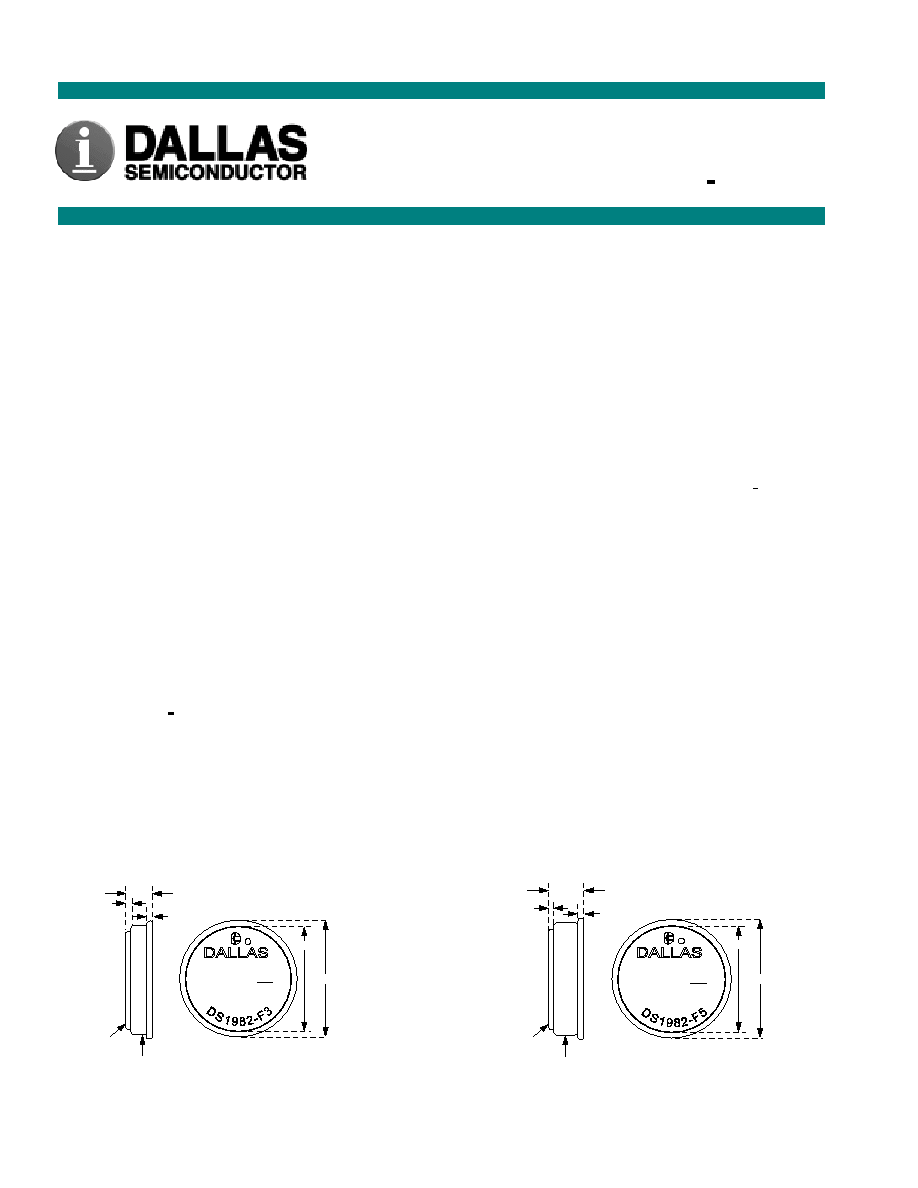
F3 MICROCAN
F5 MICROCAN
All dimensions shown in millimeters
.
DS1982
1-kbit Add-Only iButton
TM
www.iButton.com
DATA
GROUND
0.36
0.51
5.89
c
1993
YYWW REGISTERED RR
17
09
000000FBD8B3
16.25
17.35
DATA
GROUND
0.36
0.51
3.10
c
1993
YYWW REGISTERED RR
97
09
000000FBC52B
16.25
17.35

DS1982
2 of 23
ORDERING INFORMATION
DS1982-F3 F3
MicroCan
DS1982-F5 F5
MicroCan
EXAMPLES OF ACCESSORIES
DS9096P
Self-Stick Adhesive Pad
DS9101 Multi-Purpose
Clip
DS9093RA Mounting
Lock
Ring
DS9093F Snap-In
Fob
DS9092 iButton
Probe
iButton DESCRIPTION
The DS1982 1-kbit Add-Only iButton is a rugged read/write data carrier that identifies and stores relevant
information about the product or person to which it is attached. This information can be accessed with
minimal hardware, for example, a single port pin of a microcontroller. The DS1982 consists of a factory-
lasered registration number that includes an unique 48-bit serial number, an 8≠bit CRC, and an 8-bit
Family Code (09h) plus 1 kbit of EPROM which is user-programmable. The power to program and read
the DS1982 is derived entirely from the 1-Wire communication line. Data is transferred serially via the 1-
Wire protocol which requires only a single data lead and a ground return. The entire device can be
programmed and then write-protected if desired. Alternatively, the part may be programmed multiple
times with new data being appended to, but not overwriting, existing data with each subsequent
programming of the device. Note: Individual bits can be changed only from a logical 1 to a logical 0,
never from a logical 0 to a logical 1. A provision is also included for indicating that a certain page or
pages of data are no longer valid and have been replaced with new or updated data that is now residing at
an alternate page address. This page address redirection allows software to patch data and enhance the
flexibility of the device as a standalone database. The 48-bit serial number that is factory-lasered into
each DS1982 provides a guaranteed unique identity which allows for absolute traceability. The durable
MicroCan package is highly resistant to harsh environments such as dirt, moisture, and shock. Its compact
button-shaped profile is self-aligning with cup-shaped receptacles, allowing the DS1982 to be used easily
by human operators or automatic equipment. Accessories permit the DS1982 to be mounted on printed
circuit boards, plastic key fobs, photo-ID badges, ID bracelets, and many other objects. Applications
include work-in-progress tracking, electronic travelers, access control, storage of calibration constants,
and debit tokens.
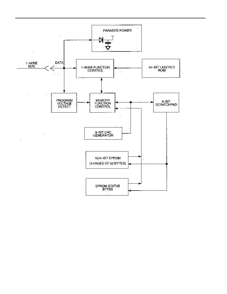
OVERVIEW
The block diagram in Figure 1 shows the relationships between the major control and memory sections of
the DS1982. The DS1982 has three main data components: 1) 64-bit lasered ROM, 2) 1024-bit EPROM,
and 3) EPROM Status Bytes. The device derives its power for read operations entirely from the 1-Wire
communication line by storing energy on an internal capacitor during periods of time when the signal line
is high and continues to operate off of this "parasite" power source during the low times of the 1-Wire
line until it returns high to replenish the parasite (capacitor) supply. During programming, 1-Wire
communication occurs at normal voltage levels and then is pulsed momentarily to the programming
voltage to cause the selected EPROM bits to be programmed. The 1-Wire line must be able to provide 12
volts and 10 milliamperes to adequately program the EPROM portions of the part. Whenever
programming voltages are present on the 1-Wire line a special high voltage detect circuit within the
DS1982 generates an internal logic signal to indicate this condition. The hierarchical structure of the 1-
Wire protocol is shown in Figure 2. The bus master must first provide one of the four ROM function
commands: 1) Read ROM, 2) Match ROM, 3) Search ROM, 4) Skip ROM. These commands operate on
the 64-bit lasered ROM portion of each device and can singulate a specific device if many are present on
the 1-Wire line as well as indicate to the bus master how many and what types of devices are present. The
protocol required for these ROM function commands is described in Figure 9. After a ROM function
command is successfully executed, the memory functions that operate on the EPROM portions of the

DS1982
3 of 23
DS1982 become accessible and the bus master may issue any one of the five memory function commands
specific to the DS1982 to read or program the various data fields. The protocol for these memory function
commands is described in Figure 6. All data is read and written least significant bit first.
64-BIT LASERED ROM
Each DS1982 contains a unique ROM code that is 64 bits long. The first 8 bits are a 1-Wire family code.
The next 48 bits are a unique serial number. The last 8 bits are a CRC of the first 56 bits. (See Figure 3).
The 64-bit ROM and ROM Function Control section allow the DS1982 to operate as a 1-Wire device and
follow the 1-Wire protocol detailed in the section "1-Wire Bus System." The memory functions required
to read and program the EPROM sections of the DS1982 are not accessible until the ROM function
protocol has been satisfied. This protocol is described in the ROM functions flow chart (Figure 9). The 1-
Wire bus master must first provide one of four ROM function commands: 1) Read ROM, 2) Match ROM,
3) Search ROM, or 4) Skip ROM. After a ROM function sequence has been successfully executed, the
bus master may then provide any one of the memory function commands specific to the DS1982 (Figure
6).
The 1-Wire CRC of the lasered ROM is generated using the polynomial X
8
+ X
5
+ X
4
+ 1. Additional
information about the Dallas Semiconductor 1-Wire Cyclic Redundancy Check is available in the Book
of DS19xx iButton Standards. The shift register acting as the CRC accumulator is initialized to 0. Then
starting with the least significant bit of the family code, 1 bit at a time is shifted in. After the 8
th
bit of the
family code has been entered, then the serial number is entered. After the 48
th
bit of the serial number has
been entered, the shift register contains the CRC value. Shifting in the 8 bits of CRC should return the
shift register to all 0s
.