
1 of 2
102099
FEATURES
ß
IEEE-approved factory programmed 64-bit
node address chip (EUI-64) with 768 bits
user-programmable OTP-EPROM
communicates with the economy of one
signal plus ground
ß
Meets the node identification requirements of
IEEE Standard 1394-1995 (FireWire
TM
)
ß
Unique, factory-lasered and tested 64-bit
registration number (8-bit family code 89H +
36-bit serial number + 12-bit UniqueWare
identifier 5E7H + 8-bit CRC tester) assures
absolute traceability because no two parts are
alike
ß
Built-in multidrop controller ensures
compatibility with other MicroLAN products
ß
Device is an "add only" memory where
additional data can be programmed into
EPROM without disturbing existing data
ß
Reduces control, address, data, power and
programming signals to a single pin
ß
Directly connects to a single port pin of a
microprocessor and communicates at up to
16.3k bits per second
ß
Presence detector acknowledges when reader
first applies voltage
ß
Low cost TO-92 or TSOC surface mount
packages
ß
Reads over a wide voltage range of 2.8V to
6.0V from -40∞C to +85∞C; programs at
11.5V to 12.0V from -40∞C to +50∞C
3 2 1
PIN ASSIGNMENT
ORDERING INFORMATION
DS2502-E64
TO-92 package
DS2502P-E64
6-pin TSOC package
FireWire
TM
is a trademark of Apple Computer,
Inc.
GLOBAL INDENTIFIER DESCRIPTION
The DS2502-E64 is a variant of the DS2502 1024-bit Add-Only Memory. It differs from the standard
DS2502 in its custom ROM family code 89H, and the UniqueWare Identifier 5E7 in place of the upper 12
bits of the standard ROM serialization field. Otherwise, the electrical and logical behavior is identical to
that of the DS2502. For technical details please refer to the DS2502 data sheet. The first 32 bytes of the
DS2502-E64's EPROM memory contain a globally unique 64-bit node address (EUI-64) and are write-
protected. The data structure follows the conventions of UniqueWare devices using Default Data
Structure (Figure 1).
DS2502-E64
IEEE EUI-64 Node Address Chip
www.dalsemi.com
SIDE VIEW
See Mech.
Drawing Section
TOP VIEW
THE DOT MARKS PIN 1
TSOC PACKAGE
E 6 4
2 5 0 2
YYWW
DATA
NC
NC
NC
NC
GND
YYWW = DATE CODE
RR = DIE REVISION CODE
CCCCCC = COUNTRY CODE
BOTTOM VIEW
TO-92
DS2502-E64
YYWWRR
CCCCCC
GND
DATA
NC
2 3
1
DS2502-E64
2 of 2
102099
The data record starts with a length byte (0CH) and the 4-byte UniqueWare Project ID 00001128H. The
next eight bytes contain the EUI-64 global identifier (node address) which consists of an incrementing
40-bit extension identifier and the IEEE-assigned 24-bit company ID value 006035H. A 16-bit CRC ends
the data record. The remaining bytes of the 32-byte memory page remain unprogrammed. Neither the 40≠
bit extension identifier nor the 24-bit company ID are related to the 64-bit ROM registration number,
which is distinct from the IEEE Standard 1394-1995 node address. The ROM registration number is used
to provide a unique address to access the DS2502-E64 when multidropped on a 1-Wire
TM
bus.
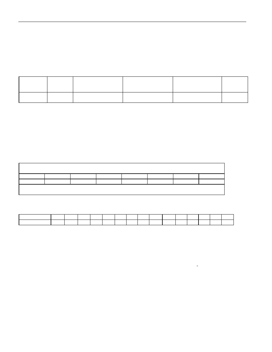
EUI-64 NODE ADDRESS CHIP DATA STRUCTURE Figure 1
(UNUSED)
CRC16
COMPANY ID
VALUE
EXTENSION ID
VALUE
PROJECT ID
LENGTH
MSB LSB
MSB
LSB
MSB
LSB
MSB
LSB
17 BYTES
FFH
2 BYTES
3 BYTES CONSTANT
006035H
5 BYTES
SERIALIZATION
4 BYTES CONSTANT
00001128H
1 BYTE
0CH
high address
low address
EXAMPLE
Assume that a manufacturer's company ID value is 006035
16
and the 40-bit extension identifier is
234567ABCD
16
. The EUI-64 value generated from these two numbers is 006035234567ABCD
16
, whose
byte and bit representations are illustrated in Figure 2. This information is stored in the DS2502-E64 as
64-bit number with the least significant byte at the lower address. Including the length byte and the CRC,
the complete set of data is shown in Figure 3.
SAMPLE EUI-64 VALUE Figure 2
MOST SIGNIFICANT
BYTE
LEAST SIGNIFICANT
BYTE
00
60
35
23
45
67
AB
CD
HEX
0000 0000
0110 0000
0011 0101
0010 0011
0100 0101
0110 0111
1010 1011
1100 1101
BINARY
MOST SIGNIFICANT
BIT
LEAST SIGNIFICANT
BIT
PHYSICAL ADDRESS AND DATA MAPPING INSIDE THE DEVICE Figure 3
ADDRESS
0E
0D
0C
0B
0A
09
08
07
06
05
04
03
02
01
00
DATA
XX
XX
00
60
35
23
45
67
AB
CD
00
00
11
28
0C
XX XX = CRC16, value depends on actual data
The four bytes at memory addresses 01 to 04 contain the UniqueWare Project ID 00001128
16
. The two
bytes at addresses 0DH and 0EH are the 16-bit CRC over the length byte, Project ID and EUI-64 value.
The least significant byte of the CRC is stored at address 0D. This CRC is generated according to the
standardized CRC16 polynomial function X
16
+ X
15
+ X
2
+ 1. For more details on generating CRC values
including examples in both hardware and software, see the "Book of DS19xx iButton Standards" or
Application Note 27.
The contents of the memory address range 0FH to 1FH is FFH. These cells cannot be altered since the
whole memory page is write-protected. The memory range from 20H to 7FH, however, is user-
programmable. It can be write-protected by programming the corresponding write-protect bit in the status
memory of the DS2502-E64.