 | –≠–ª–µ–∫—Ç—Ä–æ–Ω–Ω—ã–π –∫–æ–º–ø–æ–Ω–µ–Ω—Ç: DS80C411 | –°–∫–∞—á–∞—Ç—å:  PDF PDF  ZIP ZIP |

1 of 102
REV: 060805
Note: Some revisions of this device may incorporate deviations from published specifications known as errata. Multiple revisions of any device
may be simultaneously available through various sales channels. For information about device errata, click here:
www.maxim-ic.com/errata
.
GENERAL DESCRIPTION
The DS80C410/DS80C411 network microcontrollers offer
the highest integration available in an 8051 device.
Peripherals include a 10/100 Ethernet MAC, three serial
ports, an optional CAN 2.0B controller, 1-WireÆ Master,
and 64 I/O pins. The DS80C410 and DS80C411 also
include 64kBytes internal SRAM for user application
storage and network stack.
To enable access to the network, a full application-
accessible TCP IPv4/6 network stack and OS are provided
in the ROM. The network stack supports up to 32
simultaneous TCP connections and can transfer up to
5Mbps through the Ethernet MAC. Its maximum system-
clock frequency of 75MHz results in a minimum instruction
cycle time of 54ns. Access to large program or data
memory areas is simplified with a 24-bit addressing
scheme that supports up to 16MB of contiguous memory.
To accelerate data transfers between the microcontroller
and memory, the DS80C410 and DS80C411 provide four
data pointers, each of which can be configured to
automatically increment or decrement upon execution of
certain data pointer-related instructions. High-speed shift,
normalization, accumulate functions and 32-bit/16-bit
multiply and divide operations are optimized by the
DS80C410/DS80C411 hardware math accelerator.
The High-Speed Microcontroller User's Guide and the High-Speed
Microcontroller User's Guide: Network Microcontroller Supplement
should be used in conjunction with this data sheet. Download
both at:
www.maxim-ic.com/user_guides
.
APPLICATIONS
Industrial Control/Automation
Environmental Monitoring
Network Sensors
Data Converters (Serial-to-
Ethernet, CAN-to-
Ethernet)
Vending
Home/Office Automation
Transaction/Payment
Terminals
Remote Data-Collection
Equipment
1-Wire is a registered trademark of Dallas Semiconductor Corp.
Magic Packet is a registered trademark of Advanced Micro
Devices, Inc.
FEATURES
ß
High-Performance Architecture
Single 8051 Instruction Cycle in 54ns
DC to 75MHz Clock Rate
Flat 16MB Address Space
Four Data Pointers with Auto-Increment/
Decrement and Select-Accelerate Data Movement
16/32-Bit Math Accelerator
ß
Multitiered Networking and I/O
10/100 Ethernet Media Access Controller (MAC)
Optional CAN 2.0B Controller
1-Wire Net Controller
Three Full-Duplex Hardware Serial Ports
Up to Eight Bidirectional 8-Bit Ports (64 Digital I/O Pins)
ß
Robust ROM Firmware
Supports Network Boot Over Ethernet Using DHCP and
TFTP
Full, Application-Accessible TCP/IP Network Stack
Supports IPv4 and IPv6
Implements UDP, TCP, DHCP, ICMP, and IGMP
Preemptive, Priority-Based Task Scheduler
MAC Address can Optionally be Acquired from IEEE-
Registered DS2502-E48
ß
10/100 Ethernet Mac
Flexible IEEE 802.3 MII (10/100Mbps) and ENDEC
(10Mbps) Interfaces Allow Selection of PHY
Low-Power Operation
Ultra-Low-Power Sleep Mode with Magic PacketÆ
and Wake-Up Frame Detection
8kB On-Chip Tx/Rx Packet Data Memory with Buffer
Control Unit Reduces Load on CPU
Half- or Full-Duplex Operation with Flow Control
Multicast/Broadcast Address Filtering with VLAN
Support
Features continued on page 34.
Pin Configuration appears at end of data sheet.
Selector Guide appears at end of data sheet
.
ORDERING INFORMATION
PART TEMP
RANGE
PIN-PACKAGE
DS80C410-FNY
-40∞C to +85∞C
100 LQFP
DS80C410-FNY+
-40∞C to +85∞C
100 LQFP
DS80C411-FNY
-40∞C to +85∞C
100 LQFP
DS80C411-FNY+
-40∞C to +85∞C
100 LQFP
+ Denotes lead-free/RoHS-compliant device.
DS80C410/DS80C411
Network Microcontrollers with
Ethernet and CAN
www.maxim-ic.com
DS80C410/DS80C411 Network Microcontrollers with Ethernet and CAN
2 of 102
ABSOLUTE MAXIMUM RATINGS
Voltage Range on Any Input Pin Relative to Ground.................................................................-0.5V to +5.5V
Voltage Range on Any Output Pin Relative to Ground.....................................................-0.5V to (V
CC3
+ 0.5V)
Voltage Range on V
CC3
Relative to Ground.............................................................................-0.5V to +3.6V
Voltage Range on V
CC1
Relative to Ground.............................................................................-0.3V to +2.0V
Operating Temperature Range............................................................................................-40∞C to +85∞C
Junction Temperature...........................................................................................................+150∞C max
Storage Temperature Range.............................................................................................-55∞C to +160∞C
Soldering Temperature........................................................................See IPC/JEDEC J-STD-020 Standard
Stresses beyond those listed under "Absolute Maximum Ratings" may cause permanent damage to the device. These are stress ratings only,
and functional operation of the device at these or any other conditions beyond those indicated in the operational sections of the specifications is
not implied. Exposure to absolute maximum rating conditions for extended periods can affect device reliability.
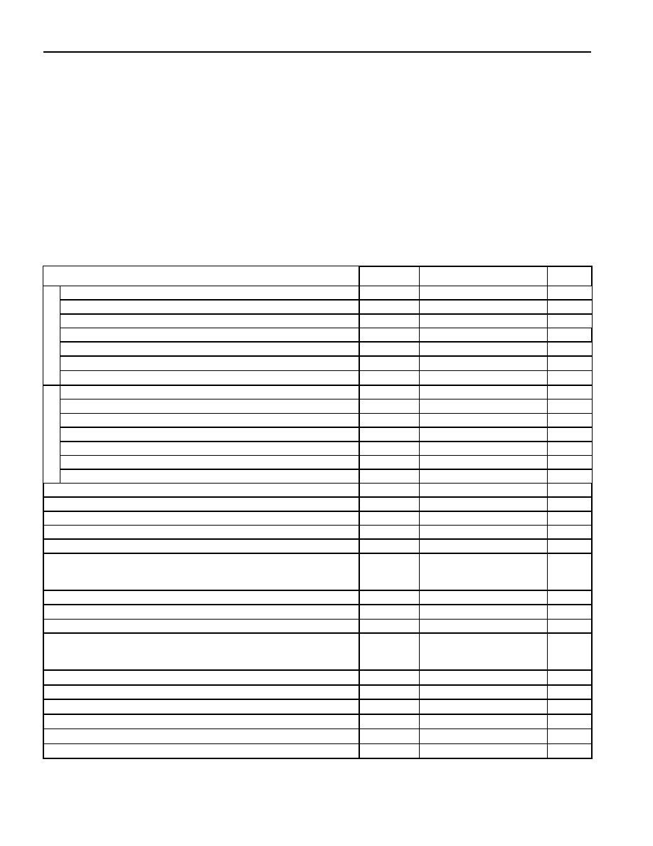
DC ELECTRICAL CHARACTERISTICS
(V
CC3
= 3.0V to 3.6V, V
CC1
= 1.8V ±10%, T
A
= -40∞C to +85∞C.) (Note 1)
PARAMETER SYMBOL
MIN
TYP
MAX
UNITS
Supply Voltage (V
CC3
) (Note 2)
V
CC3
3.0 3.3 3.6 V
Power-Fail Warning (V
CC3
) (Note 3)
V
PFW3
2.85 3.00 3.15 V
Power-Fail Reset Voltage (V
CC3
) (Note 3)
V
RST3
2.76
2.90 3.05 V
Active Mode Current (V
CC3
) (Note 4)
I
CC3
16
35
mA
Idle Mode Current (V
CC3
) (Note 4)
I
IDLE3
7 15
mA
Stop Mode Current (V
CC3
) (Not 4)
I
STOP3
1 10
mA
VCC3
Stop Mode Current, Bandgap Enabled (V
CC3
) (Note 4)
I
SPBG3
100
150
mA
Supply Voltage (V
CC1
) (Note 2)
V
CC1
1.62 1.8 1.98 V
Power-Fail Warning (V
CC1
) (Note 5)
V
PFW1
1.52 1.60 1.68 V
Power-Fail Reset Voltage (V
CC1
) (Note 5)
V
RST1
1.47
1.55 1.63 V
Active Mode Current (V
CC1
) (Note 4)
I
CC1
30
60
mA
Idle Mode Current (V
CC1
) (Note 4)
I
IDLE1
20 50
mA
Stop Mode Current (V
CC1
) (Note 4)
I
STOP1
3 20 mA
VCC1
Stop Mode Current, Bandgap Enabled (V
CC1
) (Note 4)
I
SPBG1
3 20 mA
Input Low Level
V
IL1
0.8
V
Input Low Level for XTAL1, RST, OW
V
IL2
1.0
V
Input High Level
V
IH1
2.0 V
Input High Level for XTAL1, RST, OW
V
IH2
2.4 V
Output Low Current for Port 1, 3≠7 at V
OL
= 0.4V
I
OL1
6
10 mA
Output Low Current for Port 0, 2, TX_EN, TXD[3:0], MDC, MDIO,
RSTOL, ALE, PSEN, and Ports 3≠7 (when used as any of the following:
A21≠A0,
WR, RD, CE0-7, PCE0-3) at V
OL
= 0.4V (Note 6)
I
OL2
12
20 mA
Output Low Current for OW,
OWSTP at V
OL
= 0.4V
I
OL3
10
16 mA
Output High Current for Port 1, 3≠7 at V
OH
= V
CC3
- 0.4V (Note 7)
I
OH1
-75
-50
mA
Output High Current for Port 1, 3≠7 at V
OH
= V
CC3
- 0.4V (Note 8)
I
OH2
-8 -4
mA
Output High Current for Port 0, 2, TX_EN, TXD[3:0], MDC, MDIO,
RSTOL, ALE, PSEN, and Ports 3≠7 (when used as any of the following:
A21≠A0,
WR, RD, CE0-7, PCE0-3) at V
OH
= V
CC3
- 0.4V (Notes 6, 9)
I
OH3
-16
-8
mA
Input Low Current for Port 1≠7 at 0.4V (Note 10)
I
IL
-50
-20
-10
mA
Logic 1-to-0 Transition Current for Port 1, 3≠7 (Note 11)
I
TL
-650
-400
mA
Input Leakage Current, Port 0 Bus Mode, V
IL
= 0.8V (Note 12)
I
TH0
20
50 200
mA
Input Leakage Current, Port 0 Bus Mode, V
IH
= 2.0V (Note 12)
I
TL0
-200
-50 -20
mA
Input Leakage Current, Input Mode (Note 13)
I
L
-10
0 10
mA
RST Pulldown Resistance
R
RST
50
100 200 k
W

DS80C410/DS80C411 Network Microcontrollers with Ethernet and CAN
3 of 102
Note 1:
Specifications to -40∞C are guaranteed by design and not production tested.
Note 2:
The user should note that this part is tested and guaranteed to operate down to V
CC3
= 3.0V and V
CC1
= 1.62V, while the reset
thresholds for those supplies, V
RST3
and V
RST1
respectively, may be above or below those points. When the reset threshold for a
given supply is greater than the guaranteed minimum operating voltage, that reset threshold should be considered the minimum
operating point since execution ceases once the part enters the reset state. When the reset threshold for a given supply is lower
than the guaranteed minimum operating voltage, there exists a range of voltages for either supply, (V
RST3
< V
CC3
< 1.62V) or (V
RST1
< V
CC1
< 3.0V), where the processor's operation is not guaranteed, and the reset trip point has not been reached. This should not
be an issue in most applications, but should be considered when proper operation must be maintained at all times. For these
applications, it may be desirable to use a more accurate external reset.
Note 3:
While the specifications for V
PFW3
and V
RST3
overlap, the design of the hardware makes it such that this is not possible. Within the
ranges given, there is a guaranteed separation between these two voltages.
Note 4:
Current measured with 75MHz clock source on XTAL1, V
CC3
= 3.6V, V
CC1
= 2.0V,
EA and RST = 0V, Port0 = V
CC3
, all other pins
disconnected.
Note 5:
While the specifications for V
PFW1
and V
RST1
overlap, the design of the hardware makes it such that this is not possible. Within the
ranges given, there will be a guaranteed separation between these two voltages.
Note 6:
Certain pins exhibit stronger drive capability when being used to address external memory. These pins and associated memory
interface function (in parentheses) are as follows: Port 3.6-3.7 (
WR, RD), Port 4 (CE0-3, A16-A19), Port 5.4-5.7 (PCE0-3), Port 6.0-
6.5 (
CE4-7, A20, A21), Port 7 (demultiplexed mode A0-A7).
Note 7:
This measurement reflects the weak I/O pullup state that persists following the momentary strong 0 to 1 port pin drive (V
OH2
). This
I/O pin state can be achieved by applying RST = V
CC3.
Note 8:
The measurement reflects the momentary strong port pin drive during a 0-to-1 transition in I/O mode. During this period, a one shot
circuit drives the ports hard for two clock cycles. A weak pullup device (V
OH1
) remains in effect following the strong two-clock cycle
drive. If a port 4 or 6 pin is functioning in memory mode with pin state of 0 and the SFR bit contains a 1, changing the pin to an I/O
mode (by writing to P4CNT, for example) does not enable the two-cycle strong pullup.
Note 9:
Port 3 pins 3.6 (
WR) and 3.7(RD) have a stronger than normal pullup drive for only one system clock period following the transition
of either
WR or RD from a 0 to a 1.
Note 10:
This is the current required from an external circuit to hold a logic low level on an I/O pin while the corresponding port latch bit is set
to 1. This is only the current required to hold the low level; transitions from 1 to 0 on an I/O pin also have to overcome the transition
current.
Note 11:
Following the 0 to 1 one-shot timeout, ports in I/O mode source transition current when being pulled down externally. It reaches a
maximum at approximately 2V.
Note 12:
During external addressing mode, weak latches are used to maintain the previously driven state on the pin until such time that the
Port 0 pin is driven by an external memory source.
Note 13:
The OW pin (when configured to output a 1) at V
IN
= 5.5V,
EA, MUX, and all MII inputs (TXCLk, RXCLk, RX_DV, RX_ER, RXD[3:0],
CRS, COL, MDIO) at V
IN
= 3.6V.
DS80C410/DS80C411 Network Microcontrollers with Ethernet and CAN
4 of 102
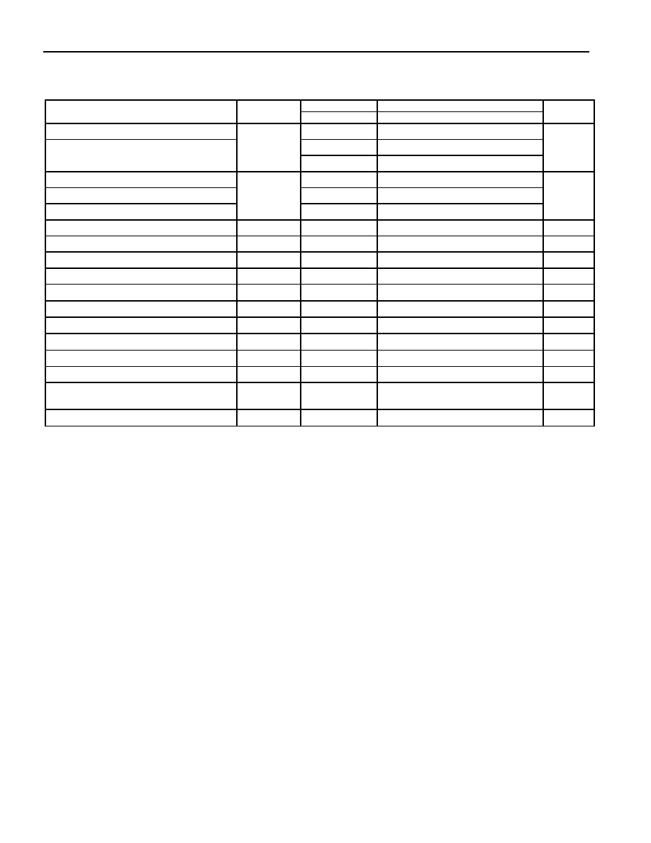
AC ELECTRICAL CHARACTERISTICS (MULTIPLEXED ADDRESS/DATA BUS)
(V
CC3
= 3.0V to 3.6V, V
CC1
= 1.8V ±10%, T
A
= -40∞C to +85∞C.) (Note 1)
75MHz VARIABLE
CLOCK
PARAMETER SYMBOL
MIN MAX
MIN
MAX
UNITS
External Crystal Frequency
4
40
16
37.5
Clock Mutliplier 2X Mode
Clock Multiplier 4X Mode
1 / t
CLK
11
18.75
MHz
External Clock Oscillator Frequency
DC
75
Clock Mutliplier 2X Mode
16
37.5
Clock Multiplier 4X Mode
1 / t
CLK
11
18.75
MHz
ALE Pulse Width
t
LHLL
15.0 t
CLCL
+ t
CHCL
- 5
ns
Port 0 Instruction Address Valid to ALE Low
t
AVLL
1.7 t
CHCL
- 5
ns
Address Hold After ALE Low
t
LLAX
4.7 t
CLCH
- 2
ns
ALE Low to Valid Instruction In
t
LLIV
14.3 2t
CLCL
+ t
CLCH
- 19
ns
ALE Low to
PSEN Low
t
LLPL
3.7 t
CLCH
- 3
ns
PSEN Pulse Width
t
PLPH
21.7 2t
CLCL
- 5
ns
PSEN Low to Valid Instruction In
t
PLIV
8.7
2t
CLCL
-18
ns
Input Instruction Hold After
PSEN
t
PXIX
0
0
ns
Input Instruction Float After
PSEN
t
PXIZ
8.3
t
CLCL
- 5
ns
Port 0 Address to Valid Instruction In
t
AVIV0
21.0
3t
CLCL
- 19
ns
Port 2, 4, 6 Address or Port 4 CE to Valid
Instruction In
t
AVIV2
24.7 3t
CLCL
+ t
CLCH
- 22
ns
PSEN Low to Address Float
t
PLAZ
0
0
ns
Note 1:
AC electrical characteristics assume 50% duty cycle for the oscillator, oscillator frequency 75MHz, and are not 100% production
tested, but are guaranteed by design.
Note 2:
All parameters apply to both commercial and industrial temperature operation, unless otherwise noted.
Note 3:
t
CLCL
, t
CLCH
, t
CHCL
are time periods associated with the internal system clock and are related to the external clock (t
CLK
) as defined in
the External Clock Oscillator (XTAL1) Characteristics table.
Note 4:
The precalculated 75MHz MIN/MAX timing specifications assume an exact 50% duty cycle.
Note 5:
All signals guaranteed with load capacitance of 80pF except Port 0, Port 2,
ALE, PSEN, RD, and WR with 100pF. The following
signals, when configured for memory interface, are also characterized with 100pF loading: Port 4 (
CE0-3, A16≠A19), Port 5.4≠5.7 (
PCE0-3), Port 6.0≠6.5 (CE4-7, A20, A21), Port 7 (demultiplexed mode A0≠A7).
Note 6:
For high-frequency operation, special attention should be paid to the float times of the interfaced memory devices so as to avoid
bus contention.
Note 7:
References to the XTAL, XTAL1 or CLK signal in timing diagrams is to assist in determining the relative occurrence of events, not
for determing absolute signal timing with respect to the external clock.

DS80C410/DS80C411 Network Microcontrollers with Ethernet and CAN
5 of 102
EXTERNAL CLOCK OSCILLATOR (XTAL1) CHARACTERISTICS
PARAMETER SYMBOL
MIN
MAX
UNITS
Clock Oscillator Period
t
CLK
See External Clock
Oscillator Frequency
Clock Symmetry at 0.5 x V
CC3
t
CH
0.45
t
CLK
0.55
t
CLK
ns
Clock Rise Time
t
CR
3
ns
Clock Fall Time
t
CF
3
ns
EXTERNAL CLOCK DRIVE
SYSTEM CLOCK TIME PERIODS (t
CLCL
, t
CHCL
, t
CLCH
)
SYSTEM CLOCK SELECTION
SYSTEM CLOCK HIGH (t
CHCL
) AND
SYSTEM CLOCK LOW (t
CLCH
)
4X/
2X
CD1 CD0
SYSTEM CLOCK
PERIOD t
CLCL
MIN MAX
1 0 0
t
CLK
/ 4
0.45 (t
CLK
/ 4)
0.55 (t
CLK
/ 4)
0 0 0
t
CLK
/ 2
0.45 (t
CLK
/ 2)
0.55 (t
CLK
/ 2)
X 1 0
t
CLK
0.45
t
CLK
0.55
t
CLK
X 1 1
256
t
CLK
0.45 (256 t
CLK)
0.55 (256 t
CLK)
Note 1:
Figure 21
shows a detailed description and illustration of the system clock selection.
Note 2: When an external clock oscillator is used in conjunction with the default system clock selection (CD1:CD0 = 10b), the
minimum/maximum system clock high (t
CHCL
) and system clock low (t
CLCH
) periods are directly related to clock oscillator duty cycle.
MOVX CHARACTERISTICS (MULTIPLEXED ADDRESS/DATA BUS) (Note 1)
(V
CC3
= 3.0V to 3.6V, V
CC1
= 1.8V ±10%, T
A
= -40
∞C to +85∞C.)
PARAMETER SYMBOL MIN
MAX
UNITS
STRETCH VALUES
C
ST
(MD2:0)
t
CLCL
+ t
CHCL
- 5
C
ST
= 0
2t
CLCL
- 5
1
£ C
ST
£ 3
MOVX ALE Pulse Width
t
LHLL2
6t
CLCL
- 5
ns
4
£ C
ST
£ 7
t
CHCL
- 5
C
ST
= 0
t
CLCL
- 6
1
£ C
ST
£ 3
Port 0 MOVX Address Valid
to ALE Low
t
AVLL2
5t
CLCL
- 6
ns
4
£ C
ST
£ 7
t
CLCH
- 2
C
ST
= 0
t
CLCL
- 2
1
£ C
ST
£3
Port 0 MOVX Address Hold
after ALE Low
t
LLAX2
and t
LLAX3
5t
CLCL
- 2
ns
4
£ C
ST
£ 7
2t
CLCL
- 5
C
ST
= 0
RD Pulse Width (P3.7 or
PSEN)
t
RLRH
(4 x C
ST
) t
CLCL
- 3
ns
1
£ C
ST
£ 7
2t
CLCL
- 5
C
ST
= 0
WR Pulse Width (P3.6)
t
WLWH
(4 x C
ST
) t
CLCL
- 3
ns
1
£ C
ST
£ 7
2t
CLCL
- 18
C
ST
= 0
RD (P3.7 or PSEN) Low to
Valid Data In
t
RLDV
(4 x C
ST
) t
CLCL
- 18
ns
1
£ C
ST
£ 7
Data Hold After
RD (P3.7 or
PSEN) High
t
RHDX
-2
ns
t
CR
t
CF
t
CLK
t
CH
XTAL1
t
CL