6-17
Dialight Corporation ∑ 1501 Route 34 South ∑ Farmingdale, NJ 07727 ∑ TEL: (732) 919-3119 ∑ FAX: (732) 751-5778 ∑www.dialight.com
6
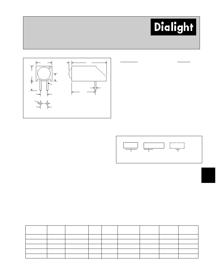
5mm
LED CBI
Æ
Circuit Board Indicator
For Backlighting
550-xx10
8.76
[.345]
.508
[.020]
12.57
[.495]
1.2
[.048]
6.22
[.245]
6.10
[.240]
3.68
[.145]
2.54
[.100]
CATHODE
Red Cathode for
Red/Green Bi-Color
Yellow Cathode for
Yellow/Green Bi-Color
2.54
[.100]
0.9
[.035]
3.05
[.120]
RECOMMENDED
P.C. BOARD LAYOUT
PART NO.
COLOR
HIGH EFFICIENCY, TINTED,
NON DIFFUSED
550-1510
Green
550-1610
Yellow
550-1710
Red
BI-COLOR
550-3010
Red/Green
550-3110
Yellow/Green
Features
∑ Extended housing and narrow viewing angle LEDs reduce
light bleed
∑ Multiple CBIs form horizontal LED arrays on 6.35mm
(0.250") center-lines.
∑ Optional stabilizing pin available - Contact Dialight for details
∑ High Contrast, UL 94 V-0 rated, black housing
∑ Oxygen index: 32%
∑ Polymer content: PBT, 0.275 g
∑ Housing stand-offs facilitate PCB cleaning
∑ Solderability per MIL-STD-202F, method 208F
∑ LEDs are safe for direct viewing per IEC 825-1, EN-60825-1
Tolerance note: As noted, otherwise:
∑ LED Protrusion: ±0.04 mm [±0.016]
∑ CBI Housing: ±0.02mm[±0.008]
Dimensions in mm [inches]
Peak
I
V
V
F
Test
Viewing
LED
Part Number
Color
Wavelength nm
mcd
Volts
Current (mA)
Angle 2
Ω
Data sheet
Page #
550-1510
Green
565
110
2.2
20
30∞
5HN-9420
6-50
550-1610
Yellow
585
110
2.2
20
30∞
5HN-9421
6-50
550-1710
Red
650
110
2.1
20
30∞
5HN-9419
6-50
550-3010
Red/Green
660/565
90/40
1.8/2.1
20
60∞
521-9651
6-46
550-3110
Yellow/Green
585/565
8.7/8.7
2.1/2.1
20
50∞
521-9724
6-46
Typical Operating Characteristics (T
A
=25∞C)
See LED data sheet for additional information
To order any of the 550-xx10 part numbers with
Reverse Polarity (Cathode Left), please add -010
to the part numbers shown above.
Standard Polarity shown in drawing: Cathode right
5 5 0
x x 1 0
0 1 0
Reverse Polarity Option
1) Cathode Left
≠010 Ordering Code Suffix required
ONLY for Reverse Polarity Option
LED Type
PART NUMBER ORDERING CODE
Series
≠
≠
See page 6-55 and 6-56 for Reference Only LED Drive Circuit Examples. See page 6-57 for Pin Out

6-46
Dialight Corporation ∑ 1501 Route 34 South ∑ Farmingdale, NJ 07727 ∑ TEL: (732) 919-3119 ∑ FAX: (732) 751-5778 ∑www.dialight.com
5mm Discrete LED
Bi-Color
Non-Tinted, Diffused
521-9651, -9724
5.00
[.197]
8.64[.340]
22.1 [.87]
MIN.
0.51
[.020]
CATHODE
GREEN,
RED/GREEN
BI-COLOR
521-9651
CATHODE
YELLOW,
YELLOW/GREEN
BI-COLOR
521-9724
1.00
[.04]
5.59
[.220]
2.54
[.100]
1.50
[.059]
MAX
PART NO.
LED COLOR
521-9651
Red/Green
521-9724
Yellow/Green
Red/Green
Yellow/Green
ABSOLUTE MAXIMUM RATINGS
(T
A
=25∞C)
-
9651
-9724
Power Dissipation (mW)
100/100
60/100
Forward Current (mA)
40/30
20/30
Derating (mA/∞C)
From 50∞C
.5/.4
.25/.40
Peak Current (mA)
200/120
80/120
Pulse width = 100 µs
Operating Temperature (∞C)
-55/+100
-55/+100
Storage Temperature (∞C)
-55/+100
-55/+100
Soldering Temperature
260∞C, 5 seconds, 1.6 mm from case
Red/Green
Yellow/Green
OPERATING CHARACTERISTICS
(T
A
=25∞C)
-9651
-9724
Luminous Intensity (mcd)
Min.
29/12.6
2.5/2.5
IF=20mA
Typical
90/40
8.7/8.7
Peak Wavelength (nm)
Typical
660/565
585/565
Peak
Viewing Angle (2
Ω
)
Typical
60∞
50∞
Forward Voltage (V)
Typical
1.8/2.1
2.1/2.1
IF=20mA
Max.
2.4/2.8
2.8/2.8
Dimensions in mm [inches]
MOUNTING CLIP: 515-0005
located on page 6-48
is the off axis angle at which the luminous intensity is half the axial luminous intensity
Solder Adherence per MIL-STD-202E, Method 208C

6-50
Dialight Corporation ∑ 1501 Route 34 South ∑ Farmingdale, NJ 07727 ∑ TEL: (732) 919-3119 ∑ FAX: (732) 751-5778 ∑www.dialight.com
5mm
High Efficiency
Tinted, Non-Diffused
5HN-xxxx
TYPE
COLOR
*5HN-9419
Red
*5HN-9420
Green
*5HN-9421
Yellow
Red
Green
Yellow
ABSOLUTE MAXIMUM RATINGS
(T
A
=25∞C)
-9419
-9420
-9421
Power Dissipation (mW)
75
75
75
Derating (mW/∞C)
From 50∞
1.5
1.5
1.5
Forward Current (mA)
25
25
25
Peak Current (mA)
60
60
60
Pulse Width
= 1 µs
Operating Temperature (∞C)
-55/+100
-55/+100
-55/+100
Storage Temperature (∞C)
-55/+100
-55/+100
-55/+100
Soldering Temperature
260∞C, 5 seconds, 1.6 mm from case
Red
Green
Yellow
OPERATING CHARACTERISTICS
(T
A
=25∞C)
-9419
-9420
-9421
Luminous Intensity (mcd)
Min.
56
56
56
IF=20mA
Typical
110
110
110
Peak Wavelength (nm)
Typical
650
565
565
Peak
Viewing Angle (2
Ω
)
30∞
30∞
30∞
Forward Voltage (V)l
Typical
2.1
2.2
2.2
IF=20mA
Max
2.55
2.55
2.55
Reverse Voltage (V), IR=100µA
Min.
5
5
5
* NOT A VALID PART
NUMBER. THIS SHEET IS FOR
REFERENCE ONLY.
is the off axis angle at which the luminous intensity is half the axial luminous intensity
Solder Adherence per MIL-STD-202E, Method 208C