 | –≠–ª–µ–∫—Ç—Ä–æ–Ω–Ω—ã–π –∫–æ–º–ø–æ–Ω–µ–Ω—Ç: LM393 | –°–∫–∞—á–∞—Ç—å:  PDF PDF  ZIP ZIP |

LM393 Dual Differential Comparator
DUAL DIFFERENTIAL COMPARATORS
Dual supplies can also be used as long as the
difference between them is 2 to 36 volts. The
LM393 is designed to operate at a temperature
range of 0
o
C to 70
o
C.
The LM393 dual differential comparator is
made up of two voltage comparators that
operate using the same power supply. THe
supply voltage can range from 2 to 36 volts.
FEATURES
l
Single or dual supplies
l
2 to 36 V Supply
l
Low Input Bias Current
l
Low Input Offset Voltage
l
Low Input Offset Current
l
Low Supply Current Drain
l
Output Compatible with TTL, MOS,
and CMOS
PIN ARRANGEMENT
8 SOP LM393CS
8 DIP LM393CD
ABSOLUTE MAXIMUM RATINGS
Power Supply Voltage
V
CC
+36 or +18
V
Input Differential Voltage Range
V
IDR
36
V
Input Common Mode Voltage Range
V
ICR
-0.3 to +36
V
Output Short Circuit-to-Ground
I
SC
Continuous
mA
Output Sink Current (1)
I
Sink
20
Power Dissipation @ 25
o
C
P
D
570
mW
Derate above 25
o
C
1/R
JA
5.7
mW/
o
C
Operating Ambient Temperature Range
T
A
0 to 70
o
C
Operating Junction Temperature
T
J
125
o
C
Storage Temperature Range
T
S
-65 to 150
o
C
Item
Symbol
Rating
Unit
Notes: 1. The max. output current may be as high as 20 mA, independent of the magnitude of V
CC
, output short circuits to
V
CC
can cause excessive heating and eventual destruction.
2. At output switch point, V
O
=
1.4 Vdc, R
S
= 0
with V
CC
from 5.0 Vdc to 30 Vdc, and over the full input
common mode range (0V to V
CC
= ≠1.5V).
3. Due to the PNP transistor inputs, bias current will flow out of the inputs. This current is essentially constant,
independent of the output state, therefore, no loading changes will exist on the input lines.
4. Input common mode of either input should not be permitted to go more than 0.3V negative of ground or minus
supply. The upper limit of common mode range is V
CC
≠1.5V.
5. Response time is specified with a 100mV step and 5.0mV of overdrive. With larger magnitudes of overdrive faster
response times are obtainable.
6. The comparator will exhibit proper output state if one of the inputs becomes greater than V
CC
, the other input
must remain within the common mode range. The low input state must not be less than ≠0.3V of ground or minus
supply.
5-16

LM393 Dual Differential Comparator
ELECTRICAL CHARACTERISTICS
V
CC
= 5.0Vdc, 0
o
C < T
A
< 70
o
C (unless otherwise noted)
Item
Symbol
Min
Typ
Max
Unit
Input Offset Voltage (2)
V
IO
mV
T
A
= 25
o
C
---
1.0
5.0
0
o
C < T
A
< 70
o
C
---
---
9.0
Input Offset Current
I
IO
nA
T
A
= 25
o
C
---
5.0
50
0
o
C < T
A
< 70
o
C
---
---
150
Input Offset Current (3)
I
IB
nA
T
A
= 25
o
C
---
25
250
0
o
C < T
A
< 70
o
C
---
---
400
Input Common Mode Voltage Range (3)
V
ICR
V
T
A
= 25
o
C
0
---
V
CC
-1.5
0
o
C < T
A
< 70
o
C
0
---
V
CC
-2.0
Voltage Gain
A
VOL
50
200
---
V/mV
R
L
> 15K, V
CC
= 15 Vdc
T
A
= 25
o
C
Large Signal Response Time
---
---
300
---
ns
Vin = TTL Logic Swing.
Vref = 1.4 Vdc
VRL = 5.0 Vdc, RL = 5.1K
T
A
= 25
o
C
Response Time (5)
t
TLH
---
13
---
µ
s
VRL = 5.0 Vdc, RL = 5.1K
T
A
= 25
o
C
Input Differential Voltage (6)
V
ID
---
---
V
CC
V
All Vin > GND or V-Supply
(if used)
Output Sink Current
I
Sink
6.0
16
---
mA
Vin- > 1.0 Vdc, Vin+ = 0 Vdc
Vo < 1.5 Vdc, T
A
= 25
o
C
Output Saturation Voltage
V
OL
mV
Vin- > 1.0 Vdc, Vin+ = 0 Vdc
---
150
400
I
Sink
< 4.0 mA, T
A
= 25
o
C
0
o
C < T
A
< 70
o
C
---
---
700
Output Leakage Current
I
OL
nA
Vin- = 0 Vdc, Vin+ > 1.0 Vdc
---
0.1
---
Vo = 5.0 Vdc, T
A
= 25
o
C
Vin- = 0 Vdc, Vin+ > 1.0 Vdc
---
---
1000
Vo = 30 Vdc, 0
o
C < T
A
< 70
o
C
Supply Current
L
CC
mA
R
L
= , T
A
= 25
o
C
---
0.4
1.0
R
L
= , V
CC
= 30 V
---
---
2.5
8
8
LM393 Dual Differential Comparator
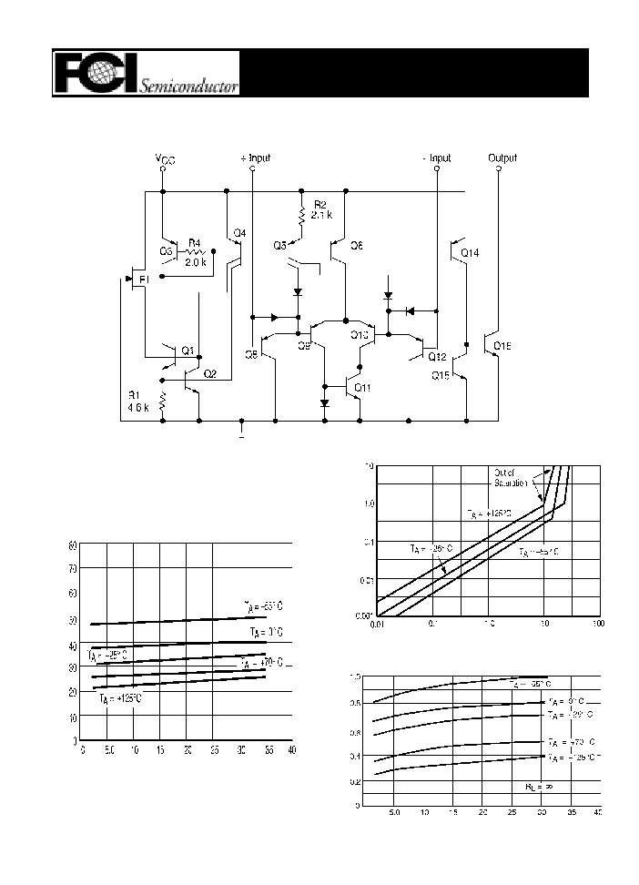
CIRCUIT SCHEMATIC
(Diagram shown is for 1 comparator)
Input Bias Curr
ent (nA)
Supply Voltage (Vdc)
Satuuration V
o
ltage (Vdc)
Output Sink Current (mA)
Supply Voltage (Vdc)
Supply Curr
ent (mA)
5-18
LM393 Dual Differential Comparator
These dual comparators feature high gain, wide bandwidth characteristics. This gives
the device oscillation tendencies if the outputs are capacitively coupled to the inputs via stray
capacitance. This oscillation manifests itself during output transitions (V
OL
to V
OH
). To alleviate
this situation, input resistors <10 k
should be used.
The addition of positive feedback (< 10 mV) is also recommended. It is good design
practice to ground all unused pins.
Differential input voltages may be larger than supply voltage without damaging the
comparator's inputs. Voltages more negative than ≠0.3 V should not be used.
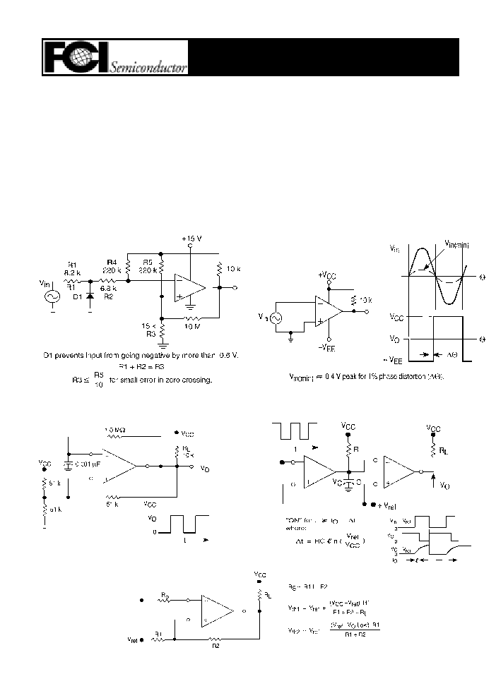
APPLICATIONS INFORMATION
Zero Crossing Detector
(Single Supply)
Zero Crossing Detector
(Split Supply)
Free-Running Square Wave Oscillator
Time Delay Generator
Comparator With Hysteresis
5-19