............................................. 1.0 ...............................................
............................................. 30 ...............................................
......................................... -65 to 150 ..........................................
............................................. 2.0 ...............................................
............................................. 50 ...............................................
............................................. 50 ...............................................
Description
Features
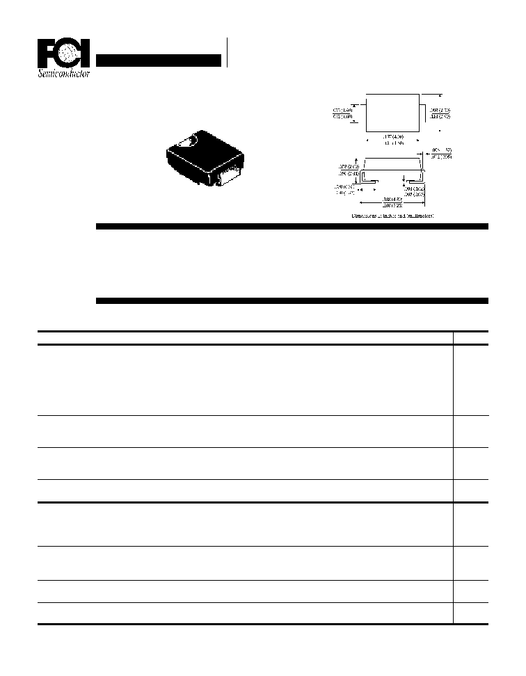
Mechanical Dimensions
Maximum Ratings
Peak Repetitive Reverse Voltage...V
RRM
RMS Reverse Voltage...V
R(rms)
DC Blocking Voltage...V
DC
UFS11 . . . 16 Series
Average Forward Rectified Current...I
F(av)
T
A
= 55
∞
C
Non-Repetitive Peak Forward Surge Current...I
FSM
@ Rated Current & Temp
Operating & Storage Temperature Range...T
J
, T
STRG
Maximum Forward Voltage @ 1.0A...V
F
Maximum DC Reverse Current...I
R
T
A
= 25
∞
C
@ Rated DC Blocking Voltage
T
A
=100
∞
C
Typical Junction Capacitance...C
J
(Note 2)
Maximum Reverse Recovery Time...t
RR
(Note 1)
Page 10-4
UFS11 . . . 16 Series
UFS11
UFS12
UFS14
UFS16
100
200
400
600
70
140
280
420
100
200
400
600
Data Sheet
1.0 Amp SMD SUPER FAST
RECTIFIERS
Units
Volts
Volts
Volts
Amps
Amps
∞
C
Volts
µ
Amps
µ
Amps
pF
ns
n HIGH CURRENT CAPABILITY
n MEETS UL SPECIFICATION 94V-0
.95
.95
1.3
1.5
n HIGH SURGE CAPABILITY
n LOW FORWARD VOLTAGE DROP
< ................... 35 ................. > < .................. 50 ................... >
Electrical Characteristics
DO-214AC
(SMA)
Data Sheet
1.0 Amp SMD SUPER FAST
RECTIFIERS
UFS11 . . . 16 Series
Page 10-5
NOTES: 1. I
F
= 0.5A, I
R
= 1.0A, Irr = 0.25A
2. Measured @ 1 MHz and applied reverse voltage of 4.0V.
Ratings at
25 Deg. C ambient
temperature
unless otherwise
specified.
Single Phase Half
Wave, 60 Hz
Resistive or
Inductive Load.
For Capacitive
Load, Derate
Current by 20%.
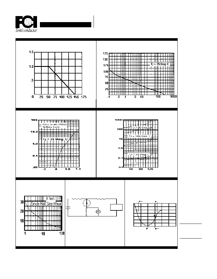
Junction Capacitance (pF)
Reverse Voltage (V)
Typical Junction Capacitance
Peak Forward Surge Current (A)
Non-Repetitive
Peak Forward Surge Current
Number of Cycles @ 60 Hz
Reverse Recovery
Characteristics
Typical Instantaneous Forward Characteristics
Oscilliscope
Note 1
Pulse
Generator
Note 2
(-)
(+)
Notes:
1. Rise Time = 7 ns Max.
Impedance = 1 megohm, 22 pF
2. Rise Time = 10 ns Max.
Source Impedance = 50 Ohms
Time Base Set @ 50/100ns/cm
+.5A
0A
-.25A
-1.0A
1 cm
Typical Reverse Characteristics
Reverse Current (
µ
µ
µ
µ
µ
A)
t
RR
Forward Current (A)
Forward Voltage (V)
50
(-)
(+)
25 VDC
Non-Inductive
1
Non-
Inductive
D.U.T 10
Percent of Rated Peak Voltage
Forward Current Derating Curve
Ambient Temperature (
∞
∞
∞
∞
∞
C)
Average Forward Current (A)