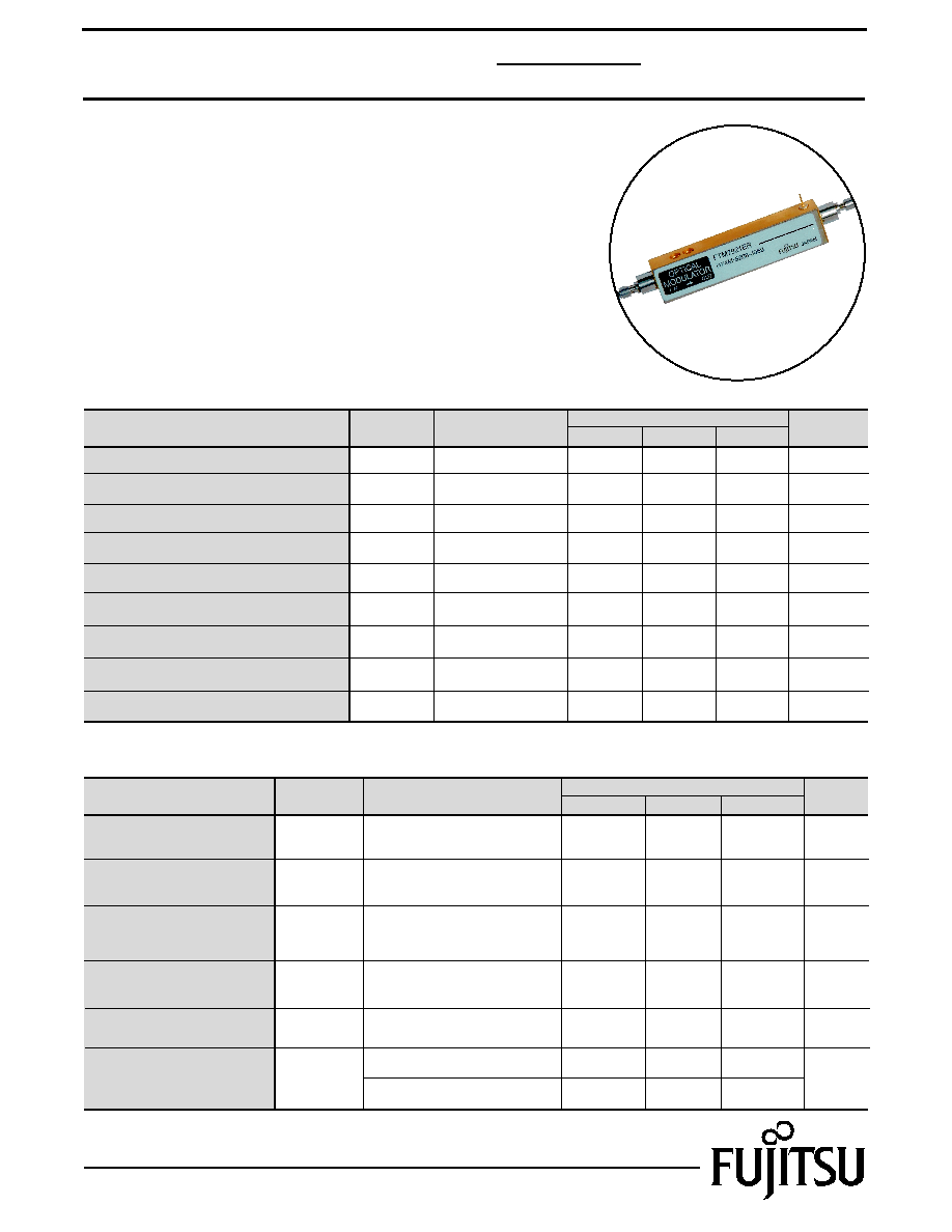
DESCRIPTION
The FTM7921ER is a Ti:LiNbO3 Dual Drive Mach-Zehnder
modulator with a modulation speed of up to 10.7 Gb/s. This optical
modulator integrates a monitor PD chip and coupler function for the
automatic bias control (ABC) to compensate for DC-drift and other
phenomena.
Parameter
Limit
ELECTRICAL CHARACTERISTICS (Tc =-5 ~ 70
įC, 25 years Unless otherwise specified)
Symbol
Condition
Unit
Max.
Typ.
RF Input Impedance
Zin
-
50
RF Return Loss
S11
130MHz ~ 5GHz
5GHz ~ 10GHz
Internally Terminated
Single Bias
At low frequency,
single drive,
and at each electrode
At 10.7 Gb/s,
Complementary Drive
dB
V
Drive Voltage
V
2.6
-
Drive Voltage
V
V
4.0
-
DC Bias Voltage
VBias
V
Min.
39
-
-
13
-
-
10
-
-
-15
15
-
Gb/s
Operating Bit Rate
-
10.7
-
-
1
Edition 1.1
June 2002
Dual Drive 10Gb/s
LN Modulator with Monitor PD
FTM7921ER
Parameter
Condition
Symbol
Operating Case Temperature
-5
-
70
Top
Case
įC
Operating Relative Humidity
5
-
85
RHop
%
DC Input Voltage
-
-
Ī16
Vin(DC)
V
Optical Input Power
-
-
50
Pin(opt)
mW
Monitor PD Reverse Voltage
-
-
20
VRM
V
Storage Temperature
-40
-
85
Tstg
Ambient
įC
-
-
1
Monitor PD Reverse Current
IRM
mA
-
-
3
Monitor PD Forward Current
IFM
mA
5
-
95
Storage Relative Humidity
RHstg
%
Unit
ABSOLUTE MAXIMUM RATINGS (Tc=25
įC, Unless otherwise specified)
Limits
Typ.
Max.
Min.
FEATURES
∑ Z-Cut Design Supports Low Drive Voltages
∑ Zero Chirp Differential Input Design
∑ Integrated Monitor Photodiode
∑ GPO RF Input Connectors

2
FTM7921ER
Parameter
Limit
OPTICAL SPECIFICATIONS (Tc=-5 ~ 70
įC, 25 years)
Unit
Symbol
Condition
Min.
Max.
On/Off Extinction Ratio
dB
dB
dB
Rext
18
-
-
Typ.
Optical Bandwidth
GHz
BW
8.5
-
-
3dB Down Relative to
130MHz, Small-signal
C Band
L Band
At Low Frequency
BOL, Input & Output
EOL, Input & Output
C Band, No Connector
L Band, No Connector
20-80%
10-90%
Balanced Input
At 10.7Gb/s Complementary Drive
Operating Wavelength
op
1570
1608
-
12
-
-
nm
1530
1570
-
Optical Return Loss
ORL
30
-
-
35
-
-
Optical Insertion Loss
IL
-
6.0
-
-
7.0
-
ps
RF Input Timing Skew
Tskw
-2.5
+2.5
-
Rise Time
Fall Time
tr
tf
-
30
-
ps
ps
-
45
-
-
-
-
Pulse Overshoot
%
-
-
10
Alpha Parameter
-
-0.2
+0.2
Pulse Undershoot
%
-
-
10
Parameter
Limit
ELECTRO-OPTICAL SPECIFICATIONS OF MONITOR PD (Tc=-5 ~ 70
įC, 25 years)
Unit
Symbol
Condition
Min.
Max.
Monitor PD V
Difference
V
%
V
-0.3
0.3
-
Typ.
Responsivity
A/W
RmAC
0.0023
0.022
-
-
Note (1)
Difference at Low
Frequency
Bias Shift
-
-20
+20
-
Note 1. Reference Table 1 for explanation
Dual Drive 10Gb/s
LN Modulator with Monitor PD
3
FTM7921ER
Dual Drive 10Gb/s
LN Modulator with Monitor PD
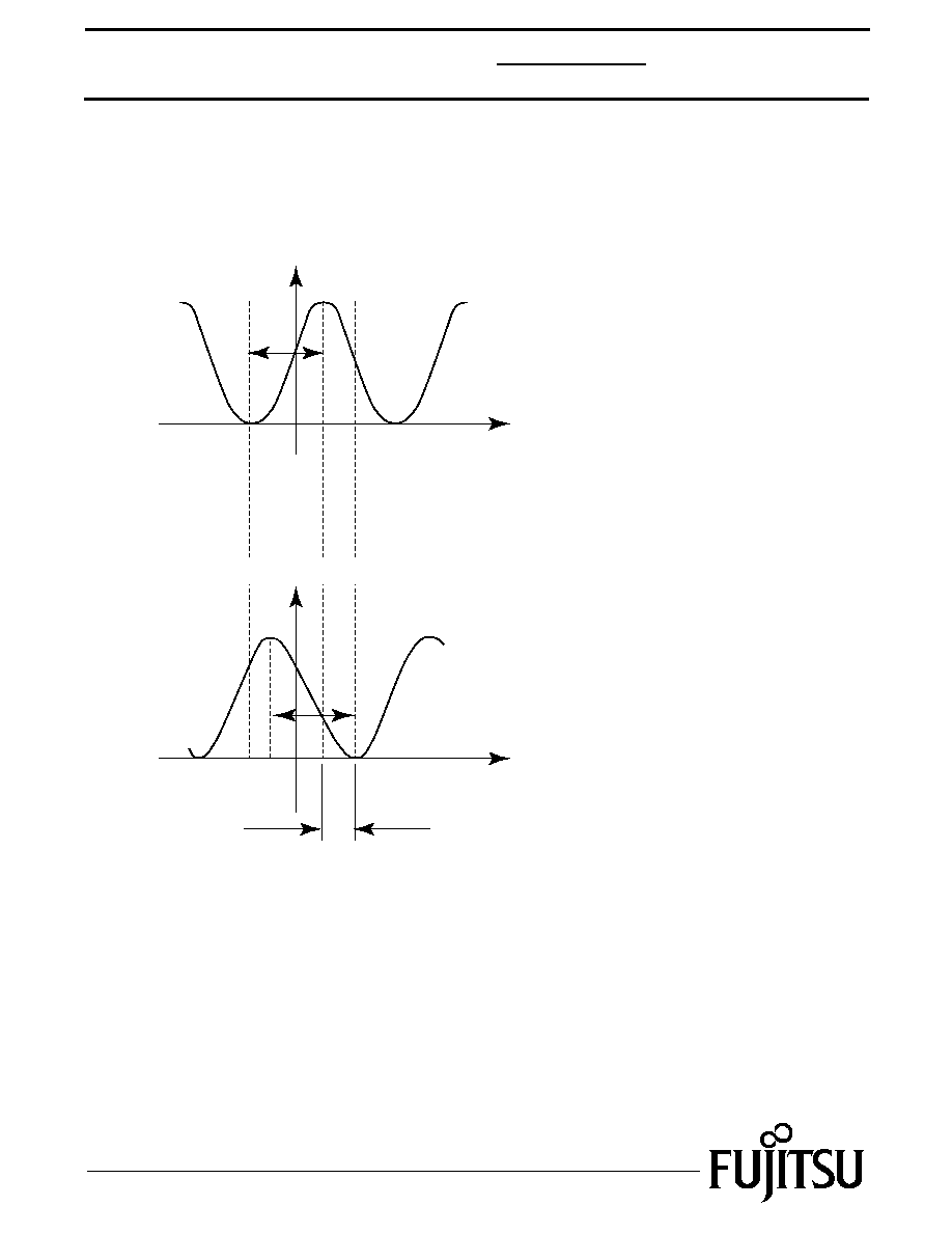
Table 1
Bias Shift
V3
V4
V2
V
Vm
V1
Applied Voltage (V)
Applied Voltage (V)
Note: These measurements are performed at a low frequency of
100Hz.
Optical Output
Monitor Current
V1: Minimum absolute applied voltage
corresponding to maximum optical output
V2: Minimum absolute applied voltage
corresponding to minimum monitor current
V3: Minimum absolute applied voltage
corresponding to maximum monitor current
V
= | V1 - V2 |
V
m = | V3 - V4 |
Bias Shift = (V1 - V3)/V
V = Vm -V

Fujitsu Compound Semiconductor Products contain gallium arsenide
(GaAs) which can be hazardous to the human body and the environment.
For safety, observe the following procedures:
CAUTION
∑ Do not put this product into the mouth.
∑ Do not alter the form of this product into a gas, powder, or liquid
through burning, crushing, or chemical processing as these by-products
are dangerous to the human body if inhaled, ingested, or swallowed.
∑ Observe government laws and company regulations when discarding this
product. This product must be discarded in accordance with methods
specified by applicable hazardous waste procedures.
Fujitsu Limited reserves the right to change products and specifications without notice.
The information does not convey any license under rights of Fujitsu Limited or others.
© 2002 FUJITSU COMPOUND SEMICONDUCTOR, INC.
Printed in U.S.A. FCSI0502M200
#4-40 UNC-2B Min 0.15 Deep (4 Places)
2 X GPO Connector
Monitor Photodiode-Anode (negative bias)
FC Connector
LC Connector
Fiber Length 59Ī4
Fiber Length 35.5Ī4
1.657Ī0.004
0.803Ī0.004
0.583
1.504
4.378Ī0.08
3.811Ī0.02
2.669Ī0.004
3.78Ī0.04
1.34Ī0.02
0.025
(0.254)
0.025
(0.02)
0.316Ī
0.008
0.61Ī
0.006
0.16
0.07
0.32Ī
0.008
0.09Ī
0.004
0.126+0.008
0.15Ī
0.004
0.43Ī
0.004
2.484Ī0.008
0.21Ī0.004
0.41Ī.004
4
FTM7921ER
Dual Drive 10Gb/s
LN Modulator with Monitor PD
For further information please contact:
FUJITSU COMPOUND SEMICONDUCTOR, INC.
2355 Zanker Rd.
San Jose, CA 95131-1138, U.S.A.
Phone: (408) 232-9500
FAX: (408) 428-9111
www.fcsi.fujitsu.com
FUJITSU QUANTUM DEVICES EUROPE LTD.
Network House
Norreys Drive
Maidenhead, Berkshire SL6 4FJ
United Kingdom
TEL: +44 (0) 1628 504800
FAX: +44 (0) 1628 504888
FUJITSU QUANTUM DEVICES
SINGAPORE PTE LTD.
Hong Kong Branch
Rm. 1101, Ocean Centre, 5 Canton Rd. Tsim Sha Tsui,
Kowloon, Hong Kong
TEL: +852-23770226
FAX: +852-23763269
FUJITSU QUANTUM DEVICES LIMITED
Business Development Division
11th Floor, Hachioji Daiichi-Seimei Bldg.
3-20-6 Myojin-cho
Hachioji-city, Tokyo 192-0046, Japan
TEL: +81-426-43-5885
FAX: +81-426-43-5582
"ER" PACKAGE
UNIT: inch