
1
FTR-P4 SERIES
(a)
Series Name
FTR-P4 Series
(b)
Contact Arrangement
C
: 1 Form C x 2 (H-Bridge)
(c)
Contact Gap
N
: 0.3mm gap
P
: 0.6mm gap
(d)
Nominal Coil Voltage
009
: 9VDC
010
: 10VDC
012
: 12VDC
(e)
Contact Material
W1
: Silver-tin oxide-indium
(f)
Custom Designation
Nil
: Standard (85∞C)
-01
: High temperature (125∞C)
FTR-P4
C
N 012 W1 ***
[Example]
(a)
(b)
(c) (d) (e) (f)
s
ORDERING INFORMATION
FTR-P4 Series
COMPACT POWER TWIN RELAY
1POLE X 2, H-BRIDGE--25 A FOR AUTOMOTIVE
APPLICATIONS
Note: The part number stamped on the relay cover does not include "FTR".
Example: Ordering part number:
FTR-P4CN012W1
Stamped on part number: P4CN012W1
s
FEATURES
q
Compact for high density packaging.
(60% volume of previous generation FBR512).
q
High contact capacity with proven contact material.
(100,000 operations, 14 V, 25 A achieved, even with reduced size).
q
Coil power savings
(600mW nominal achieved with state-of-the-art magnetic analysis/
design).
q
125∞C version is available.
q
Ease of PCB layout
(all terminals on perimeter, coil and contact terminals separated).
q
Pin compatible with low acoustic noise relay, FTR-P2.
q
Optional over-voltage circuit breaking capability
(0.6mm gap, contact our representative).
q
Packaging for auto-insertion
(tube packing, 30 relays/tube).
s
TYPICAL APPLICATIONS
Power window
Power seat
Tilt steering
Door lock
Sun roof
Retractable antenna
4
FTR-P4 SERIES
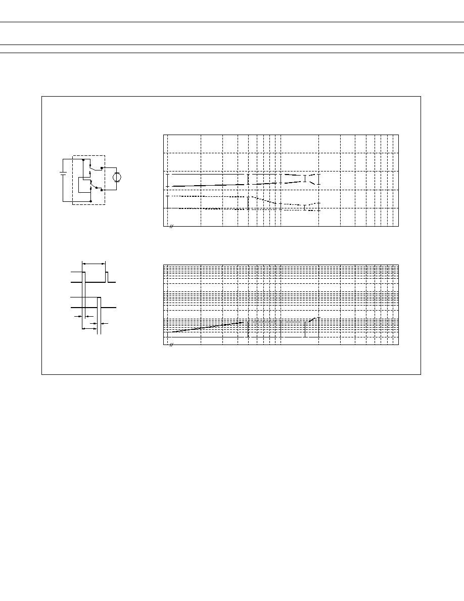
∑ Test item
14 V DC-25 A
locked motor
100K operations* minimim
0.25 seconds ON,
9.75 seconds OFF
0
1000
100
500
20
50
20
40
60
80
100
(RL-1)
10 sec
25 A
0 A
25 A
0 A
(RL-2)
0.25 sec
5 sec
0.25 sec
1000
100
500
50
20
1000
100
10
1
Initial
Number of operations* (x 10
3
times)
Initial
Number of operations* (x 10
3
times)
OPERATE
RELEASE
(Measured at 6 VDC, 1A wet)
* 1 operation = 1 forward
and 1 reverse
M
s
CHARACTERISTIC DATA
1. LIFE TEST (EXAMPLES)
∑ Current wave form
∑ Change in contact resistance
Percent of nominal coil voltage (%)
Contact Resistance (m
)
∑ Change of operate and release voltage
5
FTR-P4 SERIES
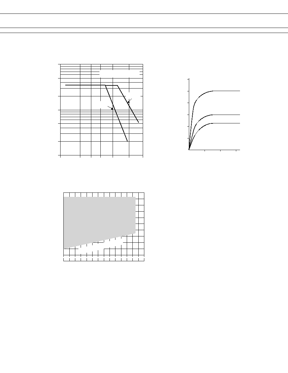
2. MAXIMUM BREAK CAPACITY
3. COIL TEMPERATURE RISE
4. OPERATING COIL VOLTAGE RANGE
-30 -20
0
20
40
60
80
100
40
60
80
100
120
140
Must-operate voltage
Ambient temperature
∞
C
Ratio of coil voltage to nominal voltage (%)
Continuous operating range
at 10A carry current
0
0
10
20
30
20
40
60
80
120
100
0.6 W
0.6 W
0.6 W
Ambient temperature: 20
∞
C
Coil temperature rise (degrees
∞
C)
Contact carrying current: 20A
Contact carrying current: 10A
Applied time (minutes)
Contact carrying current: 0.0A
30
25
20
16
14
12
10
1
2
5
10
20
50
100
Motor lock load
Source voltage (VDC)
S
wi
tc
hin
g
c
u
rr
e
n
t
(
A
)
P4CP
P4CN

