 | ÐлекÑÑоннÑй компоненÑ: LZ SERIES | СкаÑаÑÑ:  PDF PDF  ZIP ZIP |
23. LZ Series (p.146-151)
s
ORDERING INFORMATION
LZ
B
12
H
M
S
E
K
HV UC
[Example]
(a)
(b)
(c)
(d)
(e)
(f )
(g)
(h)
( i )
( j )
s
FEATURES
q
UL, CSA
q
4 kinds of contact ratings
--Low level to 10 amps switching
q
Standard and high sensitivity types available
q
High surge strength version available
q
UL class B (130
°
C) insulation type available (only plastic
sealed type)
q
Printed circuit terminals--fits grid with 0.1 inch
q
Plastic sealed type available
(a)
Series Name
LZ : LZ Series
(b)
Coil Heat Proof Class
Nil : Standard type
B : UL class B insulation type (130
°
C)
(c)
Nominal Voltage
Refer to the COIL DATA CHART
(d)
Contact Rating
Nil : 3 A
H : 5 A
V : 10 A
W : 1 A (bifurcated)
(e)
Contact Arrangement
Nil : 1 form C (SPDT)
M : 1 form A (SPST-NO)
( f )
Coil Type
Nil : Standard type
S : High sensitive type
(g)
Contact Material (Rating)
Nil : Gold overlay silver-palladium (only LZ-W)
Nil : Gold overlay silver-nickel (3 A, 5 A)
Nil : Silver alloy (10 A) (only LZ-V)
E : Silver-nickel (3 A, 5 A)
(h)
Enclosure
Nil : Flux free type
K : Plastic sealed type (recommended for new designs)
C : Plastic sealed type (with tape)
( i )
Surge Strength
Nil : Standard type (4,000 V)
HV: High dielectric strength type (6,000 V)
( j )
Standard
UC: UL, CSA approved type
LZ SERIES
POWER RELAY
1 POLE-- 1, 3, 5, 10 A
(MEDIUM LOAD CONTROL)
1
2
LZ SERIES
s
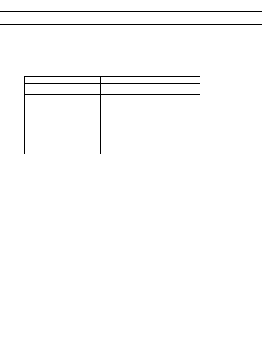
SAFETY STANDARD AND FILE NUMBERS
UL508 (File No. E56140, E45026)
C22.2 No. 14 (File No. LR35579)
Please note that UL/CSA ratings may differ from the standard ratings.
Please request when the approval markings are required on the cover and/or relay recognized by SEV is required.
Type
Nominal voltage
Contact rating
LZ- ( )W
1.5 to 48 VDC
0.8 A 240 VAC resistive
LZ- ( )WS
1.5 to 24 VDC
1 A 30 VDC/120 VAC resistive
LZ- ( )
1.5 to 48 VDC
1/10 HP 120 VAC/240 VAC
LZ- ( )S
1.5 to 24 VDC
2.5 A 240 VAC resistive
3 A 30 VDC/120 VAC resistive
Pilot duty D 150
LZ- ( )H
1.5 to 48 VDC
1/8 HP 120 VAC/240 VAC
LZ- ( )HS
1.5 to 24 VDC
4 A 240 VAC resistive
5 A 30 VDC/120 VAC resistive
Pilot duty C 150
LZ- ( )V
1.5 to 48 VDC
1/4 HP 120 VAC/240 VAC
7 A 240 VAC resistive
10 A 24 VDC/120 VAC resistive
Pilot duty C 150
3
LZ SERIES
s
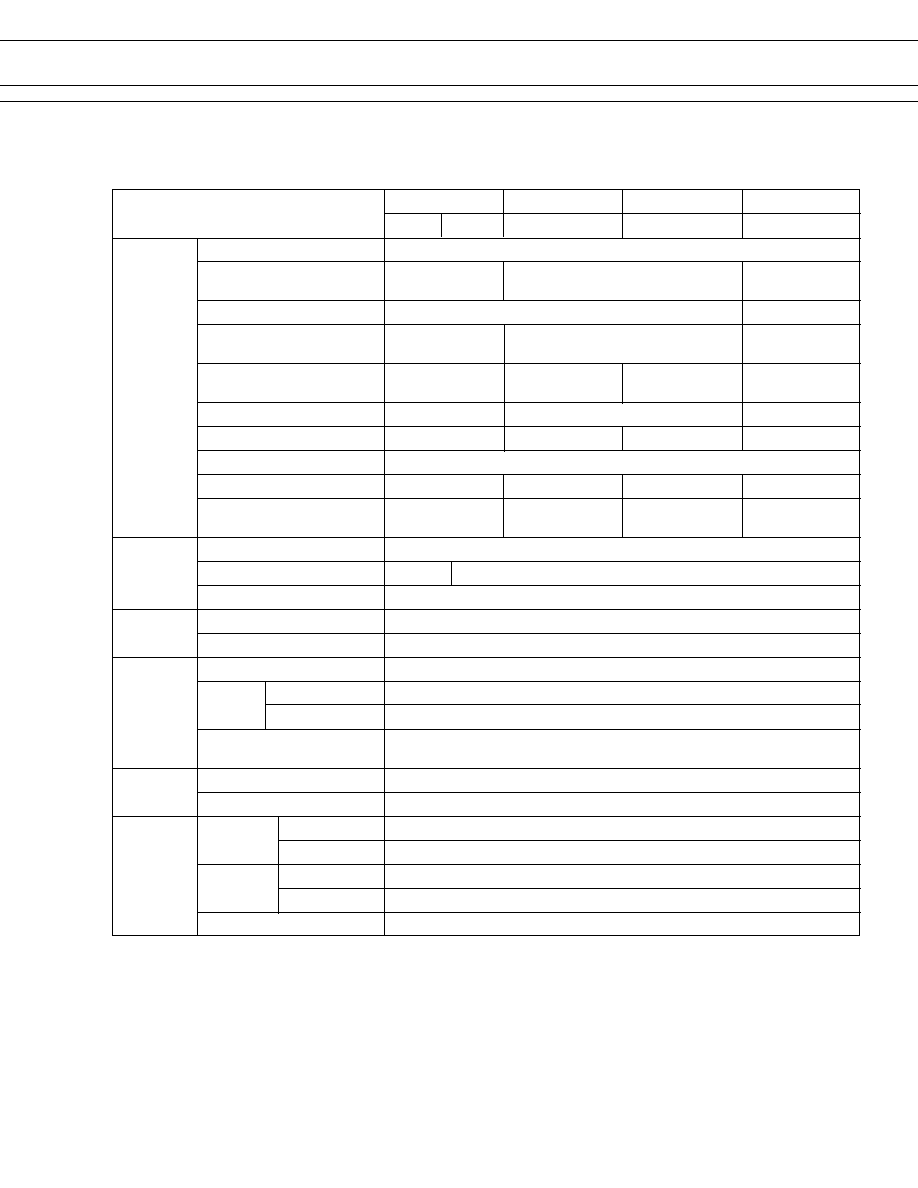
SPECIFICATIONS
LZ-( )Type (Standard Type)
10 A Type
5 A Type
3 A Type
1 A Type
Item
LZ-()V LZ-( )V
LZ-( )H, LZ-( )HE
LZ( ), LZ-( )E
LZ-( )W
Contact
Arrangement
1 form A (SPST-NO) or 1 form C (SPDT)
Material
Silver alloy
Style
Single
Bifurcated
Resistance (initial) (at 1 A 6 VDC)
Rating (resistive) 10 A 120 VAC/24 VDC 5 A 120 VAC/24 VDC 3 A 120 VAC/30 VDC 1 A 120 VAC/30 VDC
1/4 H 120 VAC 1/8 H 120 VAC 1/10 H 120 VAC
Maximum Carrying Current
10 A 5 A
1 A
Maximum Switching Power
Maximum Switching Voltage
250 VAC, 150 VDC
Maximum Switching Current
10 A 5 A
3 A
1 A
Minimum Switching Load*
1
100 mA 5 VDC 10 mA 5 VDC (LZ-H) 10 mA 5 VDC (LZ-) 0.1 mA 100 VDC
100 mA 5 VDC (LZ-HE)
Coil
Nominal Power (at 20
°
C)
0.45 to 0.60 W
Operate Power (at 20
°
C) 0.29 to0.39W
0.17 to 0.22 W
Operating Temperature
30
°
C to +70
°
C (no frost) (refer to the CHARATERISTIC DATA)
Time Value
Operate (at nominal voltage)
Maximum 7 ms
Release (at nominal voltage)
Maximum 4 ms
Insulation
Resistance (at 500 VDC)
Minimum 250 M
Dielectric between open contacts
750 VAC 1 minute
Strength between coil and contacts 2,000 VAC 1 minute
Surge Strength
Standard type: 4,000 V (at 1.2
×
50
µ
s)
High dielectric strength Type: 6,000 V (at 1.2
×
50
µ
s)
Life
Mechanical 2 x
10
7
operations minimum
Electrical
1 x 10
5
operations minimum (contact rating)
Other
Vibration Misoperation
10 to 55 Hz (double amplitude of 3.3 mm)
Resistance Endurance
10 to 55 Hz (double amplitude of 3.3 mm)
Shock Misoperation
100 m/s
2
(11
±
1 ms)
Resistance Endurance
1,000 m/s
2
(6
±
1 ms)
Weight
Approximately 7.7 g
*
1
Minimum switching loads mentioned above are reference values. Please perform the confirmation test with the actual
load before production since reference values may vary according to switching frequencies, environmental conditions
and expected reliability levels.
100 mA 5 VDC (LZ-E)
Gold overlay silver alloy
Silver alloy (LZ-HE, E)
Gold overlay
silver-palladium
1,680 VA, 240 W
960 VA, 120 W
600 VA, 90 W
190 VA, 30 W
Max. 50 m
Maximum 100 m
(LZ-HE, E)
Maximum 70 m
(LZ-H,LZ)
Maximum 100 m
4
LZ SERIES
s
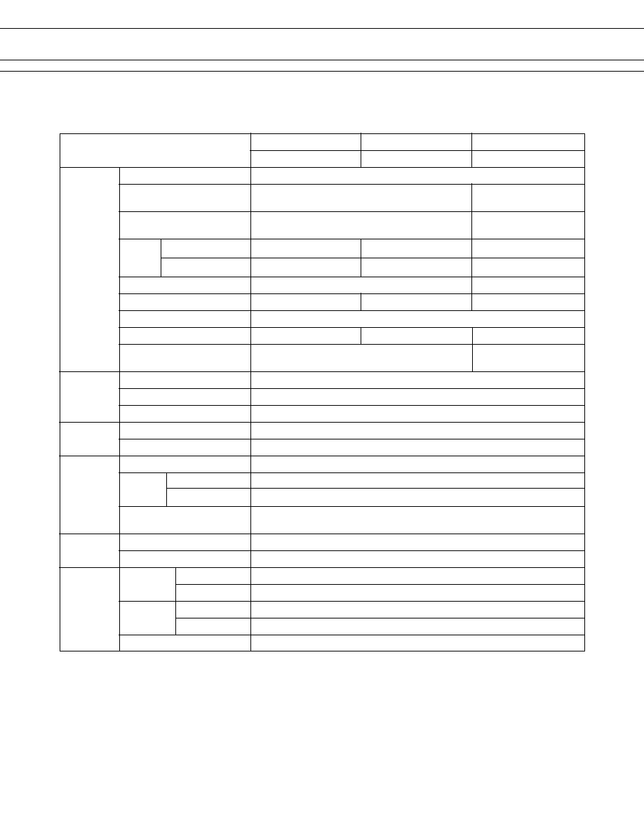
SPECIFICATIONS
LZ-( ) S Type (High Sensitive Type)
5 A Type
3 A Type
1 A Type
Item
LZ-( )HS, LZ( )HSE
LZ-( )S, LZ-( )SE
LZ-( )WS
Contact
Arrangement
1 form A (SPST-NO) or 1 form C (SPDT)
Material
Gold overlay silver alloy (single type) Gold overlay silver-palladium
(bifurcated type)
Resistance (initial) (at 1 A 6 VDC)
Maximum 70 m
(LZ-HS, S)
Maximum 100 m
(LZ-HSE, SE)
Rating Resistive
Motor Load
1/8 H 120 VAC 1/10 H 120 VAC
Maximum Carrying Current
5 A
1 A
Maximum Switching Power
960 VA, 120 W 600 VA, 90 W
190 VA, 30 W
Maximum Switching Voltage
250 VAC, 150 VDC
Maximum Switching Current
5 A 3 A 1 A
Minimum Switching Load*
1
10 mA 5 VDC (LZ-HS, S)
0.1 mA 100 mVDC
100 mA 5 VDC (LZ-HSE, SE)
Coil
Nominal Power (at 20
°
C)
0.33 W
Operate Power (at 20
°
C)
0.14 W
Operating Temperature
30
°
C to +80
°
C (no frost) (refer to the CHARACTERISTIC DATA)
Time Value
Operate (at nominal voltage)
Maximum 7 ms
Release (at nominal voltage)
Maximum 4 ms
Insulation
Resistance
Minimum 250 M
Dielectric between open contacts
750 VAC 1 minute
Strength between coil and contacts 2,000 VAC 1 minute
Surge Strength
Standard type : 4,000 V (at 1.2
×
50
µ
s)
High dielectric strength type: 6,000 V (at 1.2
×
50
µ
s)
Life
Mechanical
2
×
10
7
operations minimum
Electrical
1
×
10
5
operations minimum (rated load)
Other
Vibration Misoperation
10 to 55 Hz (double amplitude of 3.3 mm)
Resistance Endurance
10 to 55 Hz (double amplitude of 3.3 mm)
Shock Misoperation
100 m/s
2
(11
±
1 ms)
Resistance Endurance
1,000 m/s
2
( 6
±
1 ms)
Weight
Approximately 7.7 g
*
1
Minimum switching loads mentioned above are reference values. Please perform the confirmation test with the actual
load before production since reference values may vary according to switching frequencies, environmental conditions
and expected reliability levels.
Maximum 50 m
1 A 120 VAC/24 VDC
3 A 120 VAC/24 VDC
5 A 120 VAC/24 VDC
5
LZ SERIES
s
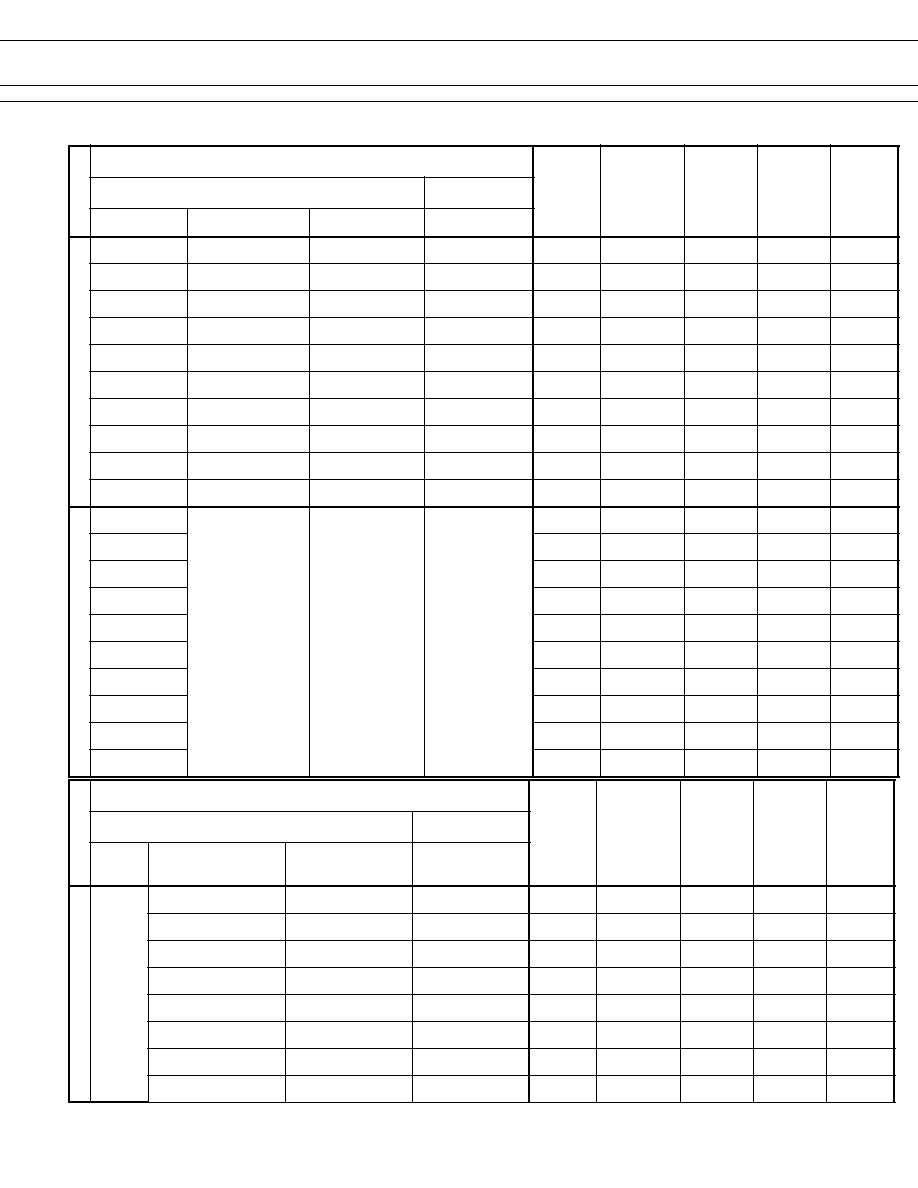
COIL DATA CHART
Note : All values in the table are measured at 20
°
C.
L
E
D
O
M
l
a
n
i
m
o
N
e
g
a
t
l
o
V
li
o
C
e
c
n
a
t
s
i
s
e
R
)
%
0
1
±
(
t
s
u
M
e
t
a
r
e
p
O
e
g
a
t
l
o
V
t
s
u
M
e
s
a
e
l
e
R
e
g
a
t
l
o
V
l
a
n
i
m
o
N
r
e
w
o
P
e
l
g
n
i
S
d
e
t
a
c
r
u
f
i
B
e
p
y
T
A
0
1
e
p
y
T
A
5
e
p
y
T
A
3
e
p
y
T
A
1
M
V
5
.
1
)
B
(
-
Z
L
)
E
(
)
M
(
H
5
.
1
)
B
(
-
Z
L
)
E
(
)
M
(
5
.
1
)
B
(
-
Z
L
)
M
(
W
5
.
1
)
B
(
-
Z
L
C
D
V
5
.
1
5
C
D
V
7
9
.
0
C
D
V
8
0
.
0
W
m
0
5
4
M
V
3
)
B
(
-
Z
L
)
E
(
)
M
(
H
3
)
B
(
-
Z
L
)
E
(
)
M
(
3
)
B
(
-
Z
L
)
M
(
W
3
)
B
(
-
Z
L
C
D
V
3
0
2
C
D
V
5
9
.
1
C
D
V
5
1
.
0
W
m
0
5
4
M
V
5
)
B
(
-
Z
L
)
E
(
)
M
(
H
5
)
B
(
-
Z
L
)
E
(
)
M
(
5
)
B
(
-
Z
L
)
M
(
W
5
)
B
(
-
Z
L
C
D
V
5
6
5
C
D
V
5
2
.
3
C
D
V
5
2
.
0
W
m
0
5
4
M
V
6
)
B
(
-
Z
L
)
E
(
)
M
(
H
6
)
B
(
-
Z
L
)
E
(
)
M
(
6
)
B
(
-
Z
L
)
M
(
W
6
)
B
(
-
Z
L
C
D
V
6
0
8
C
D
V
9
.
3
C
D
V
3
.
0
W
m
0
5
4
M
V
9
)
B
(
-
Z
L
)
E
(
)
M
(
H
9
)
B
(
-
Z
L
)
E
(
)
M
(
9
)
B
(
-
Z
L
)
M
(
W
9
)
B
(
-
Z
L
C
D
V
9
0
8
1
C
D
V
5
8
.
5
C
D
V
5
4
.
0
W
m
0
5
4
M
V
2
1
)
B
(
-
Z
L
)
E
(
)
M
(
H
2
1
)
B
(
-
Z
L
)
E
(
)
M
(
2
1
B
(
-
Z
L
)
M
(
W
2
1
)
B
(
-
Z
L
C
D
V
2
1
0
2
3
C
D
V
8
.
7
C
D
V
6
.
0
W
m
0
5
4
M
V
8
1
)
B
(
-
Z
L
)
E
(
)
M
(
H
8
1
)
B
(
-
Z
L
)
E
(
)
M
(
8
1
)
B
(
-
Z
L
)
M
(
W
8
1
)
B
(
-
Z
L
C
D
V
8
1
0
2
7
C
D
V
7
.
1
1
C
D
V
9
.
0
W
m
0
5
4
M
V
4
2
)
B
(
-
Z
L
)
E
(
)
M
(
H
4
2
)
B
(
-
Z
L
)
E
(
)
M
(
4
2
)
B
(
-
Z
L
)
M
(
W
4
2
)
B
(
-
Z
L
C
D
V
4
2
0
8
2
,
1
C
D
V
6
.
5
1
C
D
V
2
.
1
W
m
0
5
4
M
V
8
4
)
B
(
-
Z
L
)
E
(
)
M
(
H
8
4
)
B
(
-
Z
L
)
E
(
)
M
(
8
4
)
B
(
-
Z
L
)
M
(
W
8
4
)
B
(
-
Z
L
C
D
V
8
4
0
0
8
,
3
C
D
V
8
.
8
2
C
D
V
4
.
2
W
m
0
0
6
M
V
0
0
1
)
B
(
-
Z
L
)
E
(
)
M
(
H
0
0
1
)
B
(
-
Z
L
)
E
(
)
M
(
0
0
1
)
B
(
-
Z
L
)
M
(
W
0
0
1
)
B
(
-
Z
L
C
D
V
0
0
1
0
0
2
,
2
2
C
D
V
0
.
5
6
C
D
V
0
.
5
W
m
0
5
4
V
5
.
1
)
B
(
-
Z
L
C
D
V
5
.
1
5
C
D
V
2
.
1
C
D
V
8
0
.
0
W
m
0
5
4
V
3
)
B
(
-
Z
L
C
D
V
3
0
2
C
D
V
4
.
2
C
D
V
5
1
.
0
W
m
0
5
4
V
5
)
B
(
-
Z
L
C
D
V
5
6
5
C
D
V
0
.
4
C
D
V
5
2
.
0
W
m
0
5
4
V
6
)
B
(
-
Z
L
C
D
V
6
0
8
C
D
V
8
.
4
C
D
V
3
.
0
W
m
0
5
4
V
9
)
B
(
-
Z
L
C
D
V
9
0
8
1
C
D
V
2
.
7
C
D
V
5
4
.
0
W
m
0
5
4
V
2
1
)
B
(
-
Z
L
C
D
V
2
1
0
2
3
C
D
V
6
.
9
C
D
V
6
.
0
W
m
0
5
4
V
8
1
)
B
(
-
Z
L
C
D
V
8
1
0
2
7
C
D
V
4
.
4
1
C
D
V
9
.
0
W
m
0
5
4
V
4
2
)
B
(
-
Z
L
C
D
V
4
2
0
8
2
,
1
C
D
V
2
.
9
1
C
D
V
2
.
1
W
m
0
5
4
V
8
4
)
B
(
-
Z
L
C
D
V
8
4
0
0
8
,
3
C
D
V
4
.
8
3
C
D
V
4
.
2
W
m
0
0
6
V
0
0
1
)
B
(
-
Z
L
C
D
V
0
0
1
0
0
2
,
2
2
C
D
V
0
.
0
8
C
D
V
0
.
5
W
m
0
5
4
L
E
D
O
M
l
a
n
i
m
o
N
e
g
a
t
l
o
V
li
o
C
e
c
n
a
t
s
i
s
e
R
)
%
0
1
±
(
t
s
u
M
e
t
a
r
e
p
O
e
g
a
t
l
o
V
t
s
u
M
e
s
a
e
l
e
R
e
g
a
t
l
o
V
l
a
n
i
m
o
N
r
e
w
o
P
e
l
g
n
i
S
d
e
t
a
c
r
u
f
i
B
A
0
1
e
p
y
T
e
p
y
T
A
5
e
p
y
T
A
3
e
p
y
T
A
1
)
E
(
,
S
)
M
(
H
5
.
1
)
B
(
-
Z
L
)
E
(
,
S
)
M
(
5
.
1
)
B
(
-
Z
L
S
)
M
(
W
5
.
1
)
B
(
-
Z
L
C
D
V
5
.
1
8
.
6
C
D
V
7
9
.
0
C
D
V
8
0
.
0
W
m
0
3
3
)
E
(
,
S
)
M
(
H
3
)
B
(
-
Z
L
)
E
(
,
S
)
M
(
3
)
B
(
-
Z
L
S
)
M
(
W
3
)
B
(
-
Z
L
C
D
V
3
7
2
C
D
V
5
9
.
1
C
D
V
5
1
.
0
W
m
0
3
3
)
E
(
,
S
)
M
(
H
5
)
B
(
-
Z
L
)
E
(
,
S
)
M
(
5
)
B
(
-
Z
L
S
)
M
(
W
5
)
B
(
-
Z
L
C
D
V
5
0
8
C
D
V
5
2
.
3
C
D
V
5
2
.
0
W
m
0
3
3
)
E
(
,
S
)
M
(
H
6
)
B
(
-
Z
L
)
E
(
,
S
)
M
(
6
)
B
(
-
Z
L
S
)
M
(
W
6
)
B
(
-
Z
L
C
D
V
6
0
1
1
C
D
V
9
.
3
C
D
V
3
.
0
W
m
0
3
3
)
E
(
,
S
)
M
(
H
9
\
)
B
(
-
Z
L
)
E
(
,
S
)
M
(
9
)
B
(
-
Z
L
S
)
M
(
W
9
)
B
(
-
Z
L
C
D
V
9
0
5
2
C
D
V
5
8
.
5
C
D
V
5
4
.
0
W
m
0
3
3
)
E
(
,
S
)
M
(
H
2
1
)
B
(
-
Z
L
)
E
(
,
S
)
M
(
2
1
B
(
-
Z
L
S
)
M
(
W
2
1
)
B
(
-
Z
L
C
D
V
2
1
0
4
4
C
D
V
8
.
7
C
D
V
6
.
0
W
m
0
3
3
)
E
(
,
S
)
M
(
H
8
1
)
B
(
-
Z
L
)
E
(
,
S
)
M
(
8
1
)
B
(
-
Z
L
S
)
M
(
W
8
1
)
B
(
-
Z
L
C
D
V
8
1
0
9
9
C
D
V
7
.
1
1
C
D
V
9
.
0
W
m
0
3
3
)
E
(
,
S
)
M
(
H
4
2
)
B
(
-
Z
L
)
E
(
,
S
)
M
(
4
2
)
B
(
-
Z
L
S
)
M
(
W
4
2
)
B
(
-
Z
L
C
D
V
4
2
0
8
7
,
1
C
D
V
6
.
5
1
C
D
V
2
.
1
W
m
0
3
3