s
FEATURES
q
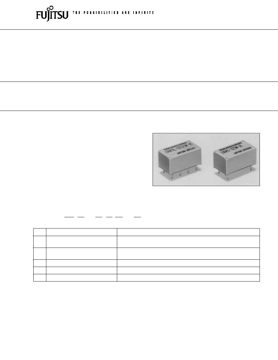
Subminiature polarized relay
q
Excellent high frequency characteristics
--Isolation
: min. 60 dB
--Insertion loss : max. 1 dB
--V.S.W.R.
: max. 1.2
}
q
High reliability--Bifurcated contacts
q
Wide operating range
q
DIL pitch terminals
q
Plastic sealed type
q
Latching type available
(a)
Series Name
UM1: UM1 Series
(b)
Operation Function
Nil : Standard type
L : Latching type
(c)
Number of Coil
Nil : Single winding type
D : Double winding type
(d)
Nominal Voltage
Refer to the COIL DATA CHART
(e)
Contact
W : Bifurcated type
(f )
Enclosure
K : Plastic sealed type
s
ORDERING INFORMATION
UM1
L
D
12 W
K
[Example]
(a)
(b)
(c)
(d) (e)
(f )
UM1 SERIES
MINIATURE RELAY
1 POLE
(HIGH FREQUENCE SIGNAL SWITCHING)
at 900 MHz
(Impedance of
the measuring
devices is 75
)
1
2
UM1 SERIES
s
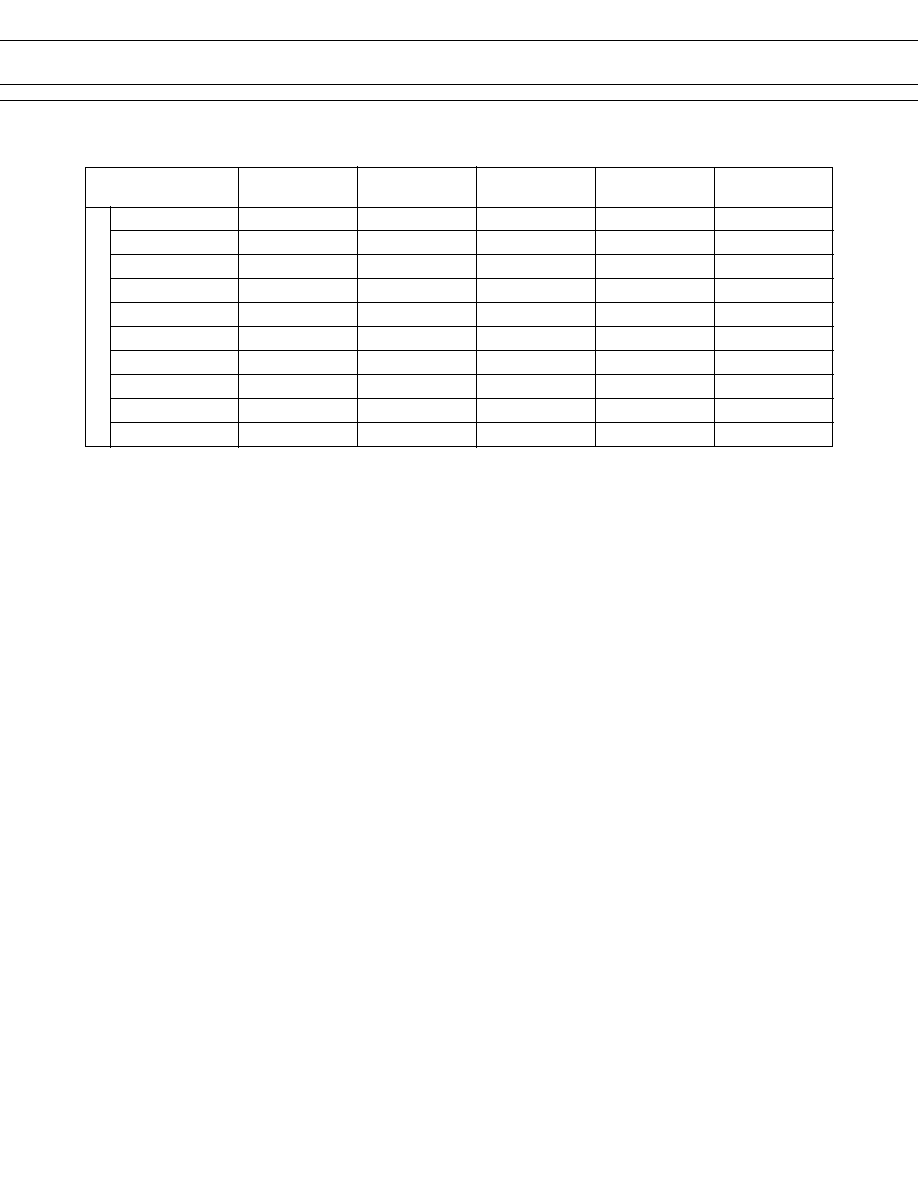
SPECIFICATIONS
Standard Type
Single Winding Latching Type Double Winding Latching Type
Item
UM1-( ) W-K
UM1L-( ) W-K
UM1L-D ( ) W-K
Contact
Arrangement
1 form C (SPDT)
Material
Gold clad (stationary contact), gold plate (movable contact)
Style
Bifurcated
Resistance (initial)
Maximum 100 m
Rating (resistive)
10 mA 24 VDC 1 W (at 900 MHz)
Maximum Carrying Current
0.5 A
Maximum Switching Power
1 W (DC) 10 W (at 900 MHz)
Maximum Switching Voltage
30 VDC
Maximum Switching Current
100 mA
Minimum Switching Load*
1
0.01 mA 10 mVDC
Excellent
Isolation
Minimum 60 dB(at 900 MHz), impedance of the measuring devices is 75
High
Frequency
Insertion Loss
Maximum 1 dB(at 900 MHz), impedance of the measuring devices is 75
Character-
istics
V.S.W.R.
Maximum 1.2(at 900 MHz), impedance of the measuring devices is 75
Coil
Nominal Power (at 20
°
C)
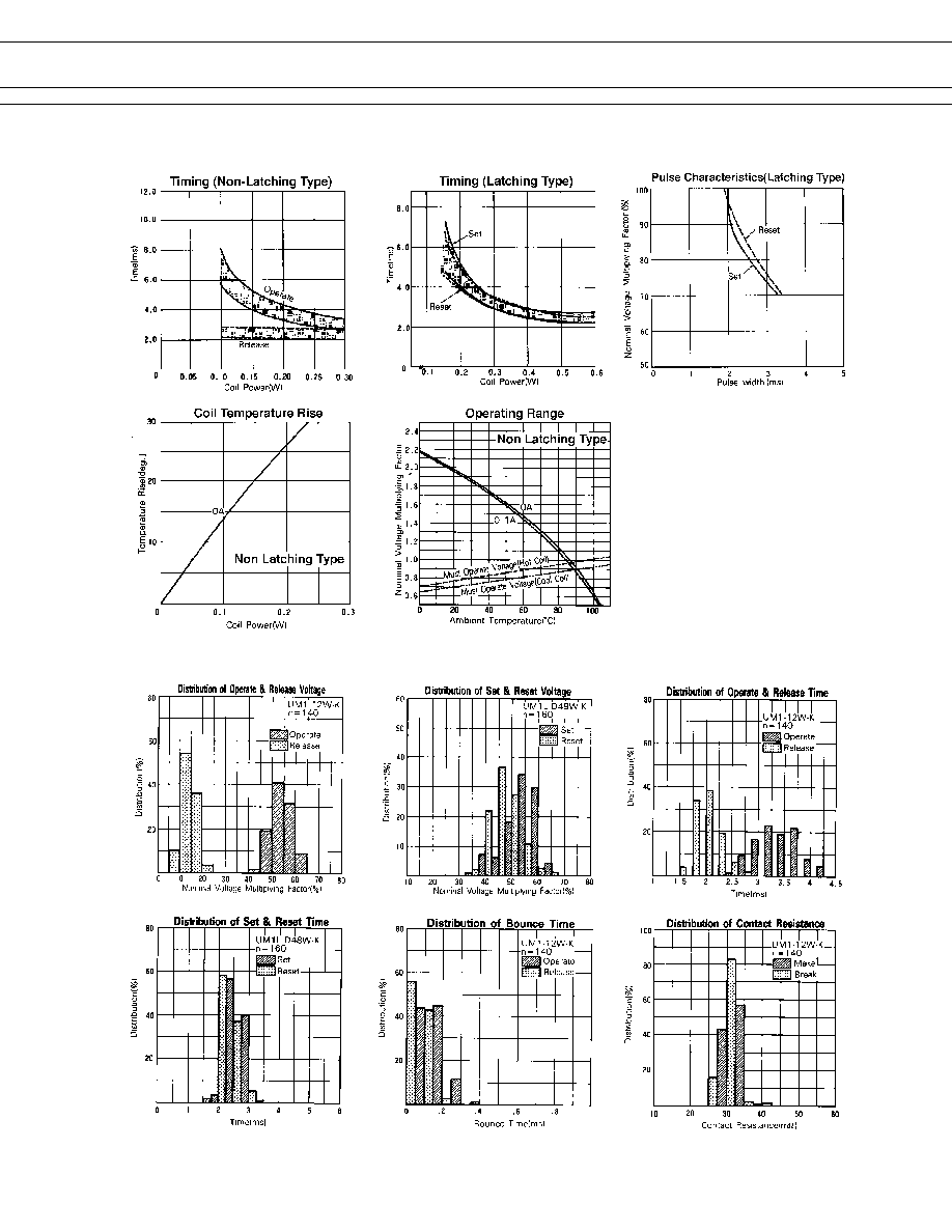
0.2 to 0.22 W 0.2 W 0.4 W
Operate Power (at 20
°
C)
0.1 to 0.11 W 0.1 W 0.2 W
Operating Temperature
30
°
C to +80
°
C (no frost)
30
°
C to +60
°
C (no frost)
Time Value
Operate (at nominal voltage)
Maximum 6 ms Maximum 6 ms (set)
Release (at nominal voltage)
Maximum 5 ms Maximum 6 ms (reset)
Insulation
Resistance (at 500 VDC)
Minimum 1,000 M
between open contacts
between contacts
500 VAC 1 minute
Dielectric and shield terminals
Strength between coil and con-
tacts, between coil
1,000 VAC 1 minute
and shield terminals
Life
Mechanical
1
×
10
6
operations minimum
Electrical
3
×
10
5
operations minimum (at nominal load)
Other
Vibration Misoperation
10 to 55 Hz (double amplitude of 3.3 mm)
Resistance Endurance
10 to 55 Hz (double amplitude of 5.0 mm)
Shock Misoperation
500 m/s
2
(11
±
1 ms)
Resistance Endurance
1,000 m/s
2
( 6
±
1 ms)
Weight
Approximately 4 g
*
1
Minimum switching loads mentioned above are reference values. Please perform the confirmation test with the actual
load before production since reference values may vary according to switching frequencies, environmental conditions
and expected reliability levels.