 | –≠–ª–µ–∫—Ç—Ä–æ–Ω–Ω—ã–π –∫–æ–º–ø–æ–Ω–µ–Ω—Ç: BQ2092 | –°–∫–∞—á–∞—Ç—å:  PDF PDF  ZIP ZIP |

Features
Provides accurate measure-
ment of available charge in
NiCd, NiMH, and Li-Ion re-
chargeable batteries
Supports SBData charge con-
trol commands for Li-Ion,
NiMH, and NiCd chemistries
Designed for battery pack inte-
gration
-
120
µA typical operating
current
-
Small size enables
implementations in as little as
3
4
square inch of PCB
Two-wire SMBus-like interface
Measurements compensated for
current and temperature
Programmable self-discharge
and charge compensation
16-pin narrow SOIC
General Description
The bq2092 Gas Gauge IC With
SMBus-Like Interface is intended
for battery-pack or in-system instal-
lation to maintain an accurate
record of available battery charge.
The bq2092 directly supports capac-
ity monitoring for NiCd, NiMH, and
Li-Ion battery chemistries.
The bq2092 uses the SMBus proto-
col that supports many of the Smart
Battery Data (SBData) commands.
The bq2092 also supports SBData
charge control.
Battery state-of-
charge, capacity remaining, remain-
ing time and chemistry are available
over the serial link. Battery-charge
state can be directly indicated using
a four-segment LED display to
graphically depict battery full-to-
empty in 25% increments.
The bq2092 estimates battery self-
discharge based on an internal
timer and temperature sensor and
user-programmable rate informa-
tion stored in external EEPROM.
The bq2092 also automatically
recalibrates or "learns" battery
capacity in the full course of a
discharge cycle from full to empty.
The bq2092 may operate directly
from three nickel chemistry cells.
With the REF output and an exter-
nal transistor, a simple, inexpensive
regulator can be built to provide V
CC
for other battery cell configurations.
An external EEPROM is used to
program initial values into the
bq2092 and is necessary for proper
operation.
1
bq2092
Gas Gauge IC with SMBus-Like Interface
V
CC
3.0≠5.5V
SCL
Serial memory
clock
SDA
Serial memory
data
SEG
1
LED segment 1
SEG
2
LED segment 2
SEG
3
LED segment 3
SEG
4
LED segment 4
V
SS
System ground
1
PN209101.eps
16-Pin Narrow SOIC
2
3
4
5
6
7
8
16
15
14
13
12
11
10
9
VOUT
REF
SCC
SCD
NC
SB
DISP
SR
VCC
SCL
SDA
SEG1
SEG2
SEG3
SEG4
VSS
SR
Sense resistor input
DISP
Display control input
SB
Battery sense input
SCD
Serial communication
data input/output
SCC
Serial communication
clock
REF
Voltage reference
output
V
OUT
EEPROM supply
output
6/99 C
Pin Connections
Pin Names

Pin Descriptions
V
CC
Supply voltage input
SCL
Serial memory clock
This output is used to clock the data
transfer between the bq2092 and the ex-
ternal nonvolatile configuration memory.
SDA
Serial memory data and address
This bi-directional pin is used to trans-
fer address and data to and from the
bq2092 and the external configuration
memory.
SEG
1
≠
SEG
4
LED display segment outputs
Each output may activate an external LED
to sink the current sourced from V
CC
.
V
SS
Ground
SR
Sense resistor input
The voltage drop (V
SR
) across pins SR and
V
SS
is monitored and integrated over time
to interpret charge and discharge activity.
The SR input is connected to the sense re-
sistor and the negative terminal of the
battery. V
SR
< V
SS
indicates discharge, and
V
SR
> V
SS
indicates charge. The effective
voltage drop, V
SRO
, as seen by the bq2092
is V
SR
+ V
OS
(see Table 3).
DISP
Display control input
DISP high disables the LED display. DISP
floating allows the LED display to be active
during charge if the rate is greater than
100mA. DISP low activates the display for 4
seconds.
SB
Secondary battery input
This input monitors the cell pack voltage as
a single-cell potential through a high-
impedance resistor divider network.
The
cell pack voltage is reported in the SBD
register function Voltage (0x09) and is com-
pared to end-of-discharge voltage and
charging voltage parameters.
NC
No connect
SCD
Serial communication data
This open-drain bidirectional pin is used to
transfer address and data to and from the
bq2092.
SCC
Serial communication clock
This open-drain bidirectional pin is used to
clock the data transfer to and from the
bq2092.
REF
Reference output for regulator
REF provides a reference output for an op-
tional micro-regulator.
V
OUT
Supply output
This output supplies power to the exter-
nal EEPROM configuration memory.
2
bq2092

Functional Description
General Operation
The bq2092 determines battery capacity by monitoring
the amount of charge input to or removed from a
rechargeable battery. The bq2092 measures discharge
and charge currents, estimates self-discharge, and
monitors the battery for low-battery voltage thresh-
olds. The charge measurement is made by monitoring
the voltage across a small-value series sense resistor
between the battery's negative terminal and ground.
The available battery charge is determined by moni-
toring this voltage over time and correcting the meas-
urement for the environmental and operating condi-
tions.
Figure 1 shows a typical battery pack application of the
bq2092 using the LED capacity display, the serial port,
and an external EEPROM for battery pack program-
ming information. The bq2092 must be configured and
calibrated for the battery-specific information to ensure
proper operation. Table 1 outlines the externally
programmable functions available in the bq2092. Refer
to the Programming the bq2092 section for further
details.
An internal temperature sensor eliminates the need
for an external thermistor--reducing cost and compo-
nents.
An internal, temperature-compensated time-
base eliminates the need for an external resonator,
further reducing cost and components.
The entire
circuit in Figure 1 can occupy less than
3
4
square inch
of board space.
3
bq2092
VCC
SCL
SDA
SEG1
SEG2
SEG3
SEG4
VOUT
REF
SCC
SCD
NC
SB
DISP
SR
BZX84C5V6
BZX84C5V6
2192L.eps
Figure 1. Battery Pack Application Diagram--LED Display

4
Parameter Name
Address
Length
Units
Design capacity
0x00/0x01
16 bits: low byte, high byte
mAh
Initial battery voltage
0x02/0x03
16 bits: low byte, high byte
mV
Fast charging current
0x04/0x05
16 bits: low byte, high byte
mA
Charging voltage
0x06/0x07
16 bit: low byte, high byte
mV
Remaining capacity alarm
0x08/0x09
16 bits: low byte, high byte
mAh
FLAGS1
0x0a
8 bits
N/A
FLAGS2
0x0b
8 bits
N/A
Current measurement gain
0x0c/0x0d
16 bits: low byte, high byte
N/A
EDV
1
0x0e/0x0f
16 bits: low byte, high byte
mV
EDV
F
0x10/0x11
16 bits: low byte, high byte
mV
Temperature offset
0x12
8 bits
0.1∞K
Maximum charge temperature/
T/t
0x13
8 bits
N/A
Self-discharge rate
0x14
8 bits
N/A
Digital filter
0x15
8 bits
N/A
Current integration gain
0x16/0x17
16 bits: low byte, high byte
N/A
Full charge percentage
0x18
8 bits
N/A
Charge compensation
0x19
8 bits
N/A
Battery voltage offset
0x1a
8 bits
mV
Battery voltage gain
0x1b/0x1c
16 bits: high byte, low byte
N/A
Serial number
0x1d/0x1e
16 bits: low byte, high byte
N/A
Hold-off timer
0x1f
8 bits
N/A
Cycle count
0x20/0x21
16 bits: low byte, high byte
N/A
Maintenance charge current
0x22/0x23
16 bits: low byte, high byte
mA
Reserved
0x24/0x31
≠
≠
Design voltage
0x32/0x33
16 bits: low byte, high byte
mV
Specification information
0x34/0x35
16 bits: low byte, high byte
N/A
Manufacturer date
0x36/0x37
16 bits: low byte, high byte
N/A
Reserved
0x38/0x3f
≠
≠
Manufacturer name
0x40/0x4f
8 + 120 bits
N/A
Device name
0x50/0x5f
8 + 120 bits
N/A
Chemistry
0x60/0x6f
8 + 120 bits
N/A
Manufacturer data
0x70/0x7f
8 +120 bits
N/A
Table 1. Configuration Memory Programming Values
Note:
N/A = Not applicable; data packed or coded. See "Programming the bq2092" for details.
bq2092

Voltage Thresholds
In conjunction with monitoring V
SR
for charge/discharge
currents, the bq2092 monitors the battery potential
through the SB pin.
The voltage potential is deter-
mined through a resistor-divider network per the
following equation:
R
R
MBV
2.25
5
4
1
=
-
where MBV is the maximum battery voltage, R
5
is
connected to the positive battery terminal, and R
4
is
connected to the negative battery terminal. R
5
/R
4
should
be rounded to the next highest integer. The voltage at
the SB pin (V
SB
) should never exceed 2.4V.
The battery voltage is monitored for the end-of-
discharge voltage (EDV), for maximum pack voltage and
for alarm warning conditions. EDV threshold levels are
used to determine when the battery has reached an
"empty" state, and the charging voltage plus 5% thresh-
old is used for fault detection during charging. The
battery voltage gain, two EDV thresholds, and charge
voltage limit are programmed via EEPROM.
See the
Programming the bq2092 section for further details.
If V
SB
is below either of the two EDV thresholds, the associ-
ated flag is latched and remains latched, independent of
V
SB
, until the next valid charge.
EDV monitoring may be disabled under certain condi-
tions. If the discharge current is greater than approxi-
mately 6A, EDV monitoring is disabled and resumes
after the current falls below 6A.
Reset
The bq2092 is reset when first connected to the battery
pack. The bq2092 can also be reset with a command
over the serial port, as described in the Software Reset
section.
Temperature
The bq2092 monitors temperature using an internal
sensor. The temperature is used to adapt charge/dis-
charge and self-discharge compensations as well as
maximum temperature and
T/t during bq2092 con-
trolled charge. Temperature may also be accessed over
the serial port. See the Programming the bq2092 section
for further details.
Layout Considerations
The bq2092 measures the voltage differential between
the SR and V
SS
pins. V
OS
(the offset voltage at the SR
pin) is greatly affected by PC board layout. For optimal
results, the PC board layout should follow the strict rule
of a single-point ground return. Sharing high-current
ground with small signal ground causes undesirable
noise on the small signal nodes. Additionally, in refer-
ence to Figure 1:
n
The capacitors (C1, C2, and C4) should be placed as
close as possible to the SB and V
CC
pins, and their paths
to V
SS
should be as short as possible. A high-quality
ceramic capacitor of 0.1
µf is recommended for V
CC
.
n
The sense resistor capacitor (C3) should be placed as
close as possible to the SR pin.
n
The sense resistor (R1) should be as close as possible
to the bq2092.
n
The IC should be close to the cells for the best
temperature measurement.
n
An optional zener may be necessary to ensure V
CC
is
not above the maximum rating during operation.
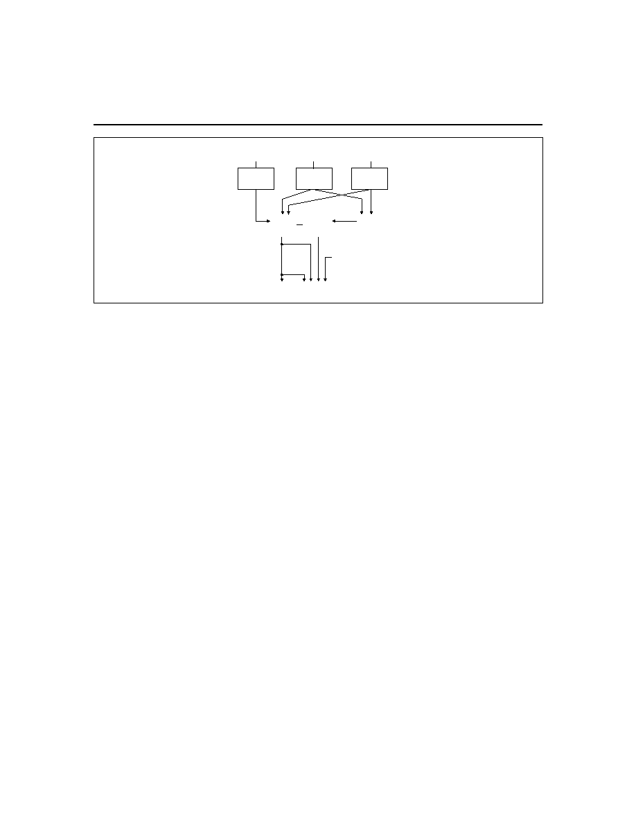
Gas Gauge Operation
The operational overview diagram in Figure 2 illus-
trates the operation of the bq2092. The bq2092 accumu-
lates a measure of charge and discharge currents, as
well as an estimation of self-discharge. Charge currents
are compensated for temperature and state-of-charge.
Self-discharge is only temperature-compensated.
The main counter, RemainingCapacity (RM), represents
the available battery capacity at any given time. Battery
charging increments the RM register, whereas battery
discharging and self-discharge decrement the RM register
and increment the Discharge Count Register (DCR).
The Discharge Count Register (DCR) is used to update
the FullChargeCapacity (FCC) register only if a
complete battery discharge from full to empty occurs
without any partial battery charges.
Therefore, the
bq2092 adapts its capacity determination based on the
actual conditions of discharge.
The battery's initial capacity is equal to the DesignCapacity
(DC).
Until FCC is updated, RM counts up to, but not
beyond, this threshold during subsequent charges.
1.
FullChargeCapacity or learned-battery
capacity:
FCC is the last measured discharge capacity of the
battery. On initialization (application of V
CC
or reset),
FCC = DC. During subsequent discharges, the FCC
is updated with the latest measured capacity in the
Discharge Count Register, representing a discharge
from full to below EDV1. A qualified discharge is
necessary for a capacity transfer from the DCR to the
FCC register. The FCC also serves as the 100% ref-
erence threshold used by the relative state-of-charge
calculation and display.
5
bq2092
2.
DesignCapacity (DC):
The DC is the user-specified battery capacity and is
programmed by using an external EEPROM. The
DC also provides the 100% reference for the abso-
lute display mode.
3.
Remaining Capacity (RM):
RM counts up during charge to a maximum value of
FCC and down during discharge and self-discharge to
0. RM is reset to 0000Ah when EDV1 = 1 and a valid
charge is detected. To prevent overstatement of
charge during periods of overcharge, RM stops in-
crementing when RM = FCC. RM may optionally
be written to a user-defined value when fully
charged when the battery pack is under bq2092
charge control. See the Charge Control section for
further details.
4.
Discharge Count Register (DCR):
The DCR counts up during discharge independent
of RM and can continue increasing after RM has
decremented to 0. Before RM = 0 (empty battery),
both discharge and self-discharge increment the
DCR.
After RM = 0, only discharge increments
the DCR. The DCR resets to 0 when RM = FCC.
The DCR does not roll over but stops counting
when it reaches FFFFh.
The DCR value becomes the new FCC value on the
first charge after a valid discharge to V
EDV1
if:
n
No valid charge initiations (charges greater than
10mAh, where V
SRO
> |V
SRD
|) occurred during
the period between RM = FCC and EDV1 de-
tected.
n
The self-discharge count is not more than
256mAh.
n
The temperature is
273∞K (0∞C) when the
EDV1 level is reached during discharge.
The valid discharge flag (VDQ) indicates whether
the present discharge is valid for FCC update. FCC
cannot be reduced by more than 256mAh during
any single cycle.
Charge Counting
Charge activity is detected based on a positive voltage
on the V
SR
input.
If charge activity is detected, the
bq2092 increments RM at a rate proportional to V
SRO
and, if enabled, activates an LED display.
Charge
actions increment the RM after compensation for charge
rate and temperature.
The bq2092 determines charge activity sustained at a
continuous rate equivalent to V
SRO
> |V
SRD
|. A valid
charge equates to sustained charge activity
greater than 10 mAh. Once a valid charge is detected,
charge counting continues until V
SRO
falls below
|V
S R D
|.
V
S R D
is a programmable threshold as
described in the Digital Magnitude Filter section.
Discharge Counting
All discharge counts where V
SRO
< |V
SRD
| cause the
RM register to decrement and the DCR to increment.
V
SRD
is a programmable threshold as described in the
Digital Magnitude Filter section.
Self-Discharge Estimation
The bq2092 continuously decrements RM and incre-
ments DCR for self-discharge based on time and
temperature. The self-discharge rate is dependent on
the battery chemistry. The bq2092 self-discharge esti-
mation rate is externally programmed in EEPROM
6
bq2092
Rate and
Temperature
Compensation
Temperature
Compensation
Charge
Current
Discharge
Current
Self-Discharge
Timer
Remaining
Capacity
(RM)
Full
Charge
Capacity
(FCC)
Discharge
Count
Register
(DCR)
<
Qualified
Transfer
+
Temperature, Other Data
+
-
-
+
Inputs
Main Counters
and Capacity
Reference (FCC)
Outputs
Two-Wire
Serial Interface
Chip-Controlled
Available Charge
LED Display
Rate and
Temperature
Compensation
Figure 2. Operational Overview

and can be programmed from 0 to 25% per day at
20-30∞C. This rate doubles every 10∞C increase until T
> 70
∞C or is halved every 10∞ decrease until T < 10∞C.
The self-discharge estimate reduces RM by 0.39% of its
current value at time intervals spaced so that the aver-
age reduction equals the programmed value adjusted for
temperature. The EEPROM program constant is the 2's
complement of 52 73
.
X , where X
day
= %
self-discharge
rate desired at 25
∞C.
Charge Control
The bq2092 supports SBD charge control by broadcast-
ing ChargingCurrent() and ChargingVoltage() to the
Smart Charger address. Smart Charger broadcasts can
be disabled by writing bit 14 of Battery Mode() to 1. The
bq2092-based charge control can be enabled by setting
bit 4 in FLAGS2 (MSB of 0x2f) to 1. See Programming
the bq2092 for further details. If the Fully_Charged bit
is not set in BatteryStatus, the bq2092 broadcasts the
fast charge current and voltage to the Smart Charger.
The bq2092 broadcasts the maintenance current values
(trickle rate) if the Fully_Charged bit is set or Voltage is
below EDVF.
The bq2092 internal charge control is compatible with
nickel-based and Li-Ion chemistries.
For Li-Ion, the bq2092 broadcasts the required Charg-
ingCurrent and ChargingVoltage according to the values
programmed in the external EEPROM. During a valid
charge (VQ = 1), the bq2092 signals a valid charge
termination when the Terminate_Charge_Alarm and
Fully_Charged bits are set in BatteryStatus. These bits
are set when the battery is charged more than 256mAh
above FCC.
For nickel-based chemistries, the bq2092 broadcasts the
required charge current and voltage according to the
programmed values in the external EEPROM.
Maxi-
mum temperature and
T/t are used as valid charge
termination methods. Note: Nickel-based chemistries
require a charge voltage higher than the maximum cell
voltage during charge to ensure constant-current charg-
ing. During a valid charge (VQ = 1), if the bq2092 deter-
mines a maximum temperature condition, a
T/t rate
greater than the programmed value, or a charge state
greater than 256mAh above FCC, then the Termi-
n a t e _ C h a r g e _ A l a r m , O v e r _ C h a r g e _ A l a r m , a n d
Fully_Charged bits are set in BatteryStatus.
Once the bq2092 detects a valid charge termination, the
Fully_Charged bit, Terminate_Charge_Alarm, and
Over_Charge_Alarm bits are set and the ChargingCurrent
is set to zero. Once the terminating condition ceases, the
Terminate_Charge_Alarm and OverCharge Alarm bits are
cleared and the ChargingCurrent is set to the maintenance
rate. The bq2092 requests the maintenance current and
charging voltage until RM falls below the full charge
percentage. Once this occurs, the Fully_Charged bit is
cleared, and the bq2092 requests the fast charging current
and charging voltage.
During fast charge, the bq2092 suspends charge by
requesting zero current and setting the Termi-
nate_Charge_Alarm bit in BatteryStatus.
Charge is
suspended if the actual charge current is 25% greater
t h a n t h e p r o g r a m m e d ch a r g e d c u r r e n t .
I f t h e
programmed charge current is less than 1024mA, over-
current suspend occurs if the actual charge current is
256mA greater than the programmed value. Charge is
also suspended if the actual battery voltage is 5%
greater than the programmed charge voltage.
If the
battery temperature is greater than the programmed
maximum temperature before charge, then the bq2092
suspends charge requests until the temperature falls
below 50∞C.
If the battery temperature is less than 0∞C, the charging
current sets to maintenance (trickle) charge current.
The fast charging current is requested when the
temperature is above 5
∞C.
T/t
The
T/t used by the bq2092 is programmable in both
the temperature step (1.6
∞C≠4.6∞C) and time step (20
seconds≠320seconds). Typical settings for 1
∞C/min
include 2
∞C over 120 seconds and 3∞C over 180 seconds.
Longer times are required for increased slope resolution.
T
t
is set by the formula:
T
t
=
(
)
[
]
lower nibble of 0 13 in E PROM
lower nibble
2
+
2
16
2' s
(
)
[
]
of 0 1f in E PROM
C
minute
2
3 33
.
o
In addition to the
T/t timer, there is a hold-off timer,
which starts when the battery is being charged at more
than 256mA and the temperature is above 25
∞C. (This is
valid only for NiMH chemistry, bit 5 in FLAGS2 set to
0.) Until this timer expires,
T/t is suspended. If the
temperature falls below 25
∞C, or if charging current
fallls below 255mA, the timer is reset and restarts only
if the above conditions are once again met.
Safety Termination
If charging continues for more than
256mAh beyond
R M = F C C, t h e Te r m i n a t e _ C h a r g e _ A l a r m a n d
Fully_Charged bits are set, and the charging current is
modified to request maintenance current. If the battery
is discharged from full by less than 256mAh, then the
safety overcharge termination, for NiMH only, is allowed
to extend to 512 mAh.
Updating RM after a valid charge termination, RM may
optionally be set to a value from 0 to 100% of the Full-
ChargeCapacity. If RM is below the value programmed
7
bq2092

in full charge percentage, RM is set to full charge
percentage of FCC on valid charge termination. If RM is
above the full charge percentage, RM is not modified.
Count Compensations
Charge activity is compensated for temperature and
state-of-charge before updating the RM and/or DCR. RM
is compensated for temperature before updating the RM
register.
Self-discharge estimation is compensated for
temperature before updating RM or DCR.
Charge Compensation
Charge efficiency is compensated for state-of-charge,
temperature, and battery chemistry. For Li-Ion chemis-
try cells, the charge efficiency is unity for all cases. The
charge efficiency for nickel chemistry cells, however, is
adjusted using the following equation:
RM
RM
Q
Q
EFC
ET
=
-
(
)
where RelativeStateofCharge
FullChargePercentage
and Q
EFC
is the programmed fast charge efficiency vary-
ing from .75 to .99.
RM
RM
Q
Q
ETC
ET
=
-
(
)
where RelativeStateofCharge
FullChargePercentage
and Q
ETC
is the programmed maintenance (trickle)
charge efficiency varying from 0.50 to 0.97.
Q
ET
is used to adjust the charge efficiency as the battery
temperature increases according to the following:
Q
if T
ET
=
<
0
30
∞C
Q
C
T
C
ET
=
∞
<
∞
0 02
30
40
.
if
Q
T
C
ET
=
∞
0 05
40
.
if
Remaining Capacity Compensation
The bq2092 adjusts the RM as a function of tempera-
ture. This adjustment accounts for the reduced capacity
of the battery at colder temperatures. The following
equation is used to adjust RM:
If T
C
∞
5
RemainingCapacity
Nominal Available Capacity (NAC)
=
If T < 5∞C
RM()
NAC()
TCC
T
5 C))
=
+
- ∞
(
(
1
Where T = temperature
∞C
TCC = 0.004
RM adjusts upward to Nominal Available Capacity as
the temperature increases.
Digital Magnitude Filter
The bq2092 has a programmable digital filter to elimi-
nate charge and discharge counting below a set
threshold. Table 2 shows typical digital filter settings.
The proper digital filter setting can be calculated
using the following equation.
|V
SRD
(mV)| = 45 / DMF
Error Summary
Capacity Inaccurate
The FCC is susceptible to error on initialization or if no
updates occur. On initialization, the FCC value includes
the error between the design capacity and the actual
capacity. This error is present until a valid discharge
occurs and FCC is updated (see the DCR description on
page 6). The other cause of FCC error is battery wear-
out. As the battery ages, the measured capacity must be
adjusted to account for changes in actual battery capac-
ity.
Periodic discharges from full to empty will mini-
mize errors in FCC.
Current-Sensing Error
Table 3 illustrates the current-sensing error as a func-
tion of V
SR
.
A digital filter eliminates charge and
discharge counts to the RM register when V
SRO
is
between V
SRQ
and V
SRD
.
Display
The bq2092 can directly display capacity information
using low-power LEDs. The bq2092 displays the battery
charge state in either absolute or relative mode. In rela-
tive mode, the battery charge is represented as a
percentage of the FCC. Each LED segment represents
25% of the FCC.
8
bq2092
DMF
DMF
Hex.
|V
SRD
(mV)|
75
4B
±0.60
100
64
±0.45
150 (default)
96
±0.30
175
AF
±0.26
200
C8
±0.23
Table 2. Typical Digital Filter Settings

In absolute mode, each segment represents a fixed
amount of charge, 25% of the design capacity. As the
battery wears out over time, it is possible for the FCC to
be below the design capacity.
In this case, all of the
LEDs may not turn on in absolute mode, representing
the reduction in the actual battery capacity.
The displayed capacity is compensated for the present
battery temperature. The displayed capacity varies as
temperature varies, indicating the available charge at
the present conditions.
When DISP is tied to V
CC
, the SEG
1≠4
outputs are inac-
tive. When DISP is left floating, the display becomes
active whenever the bq2092 detects a charge rate of
100mA or more. When pulled low, the segment outputs
become active immediately for a period of approximately
4 seconds. The DISP pin must be returned to float or
V
CC
to reactivate the display.
The segment outputs are modulated as two banks of two,
with segments 1 and 3 alternating with segments 2 and 4.
The segment outputs are modulated at approximately
100Hz with each segment bank active for 30% of the period.
SEG
1
blinks at a 4Hz rate whenever V
SB
has been
detected to be below V
EDV1
(EDV
1
= 1), indicating a low-
battery condition. V
SB
below V
EDVF
(EDV
F
= 1) disables
the display output.
Microregulator
The bq2092 can operate directly from three nickel chem-
istry cells. To facilitate the power supply requirements
of the bq2092, an REF output is provided to regulate an
external low-threshold n-FET. A micropower source for
the bq2092 can be inexpensively built using the FET
and an external resistor; see Figure 1.
Note that an
optional zener diode may be necessary to limit V
CC
during charge.
Communicating With the bq2092
The bq2092 includes a simple two-pin (SCC and SCD)
bidirectional serial data interface. A host processor uses
the interface to access various bq2092 registers; see
Table 4. This allows battery characteristics to be easily
monitored. The open-drain SCD and SCC pins on the
bq2092 are pulled up by the host system, or may be
connected to V
SS
, if the serial interface is not used.
The interface uses a command-based protocol, where the
host processor sends the battery address and an eight-
bit command byte to the bq2092. The command directs
the bq2092 to either store the next data received to a
register specified by the command byte or output the
data specified by the command byte.
bq2092 Data Protocols
The host system, acting in the role of a Bus master, uses
the read word and write word protocols to communicate
integer data with the bq2092. (See Figure 3.)
Host-to-bq2092 Message Protocol
The Bus Host communicates with the bq2092 using one
of three protocols:
n
Read word
n
Write word
n
Read block
The particular protocol used is a function of the
command. The protocols used are shown in Figure 3.
Host-to-bq2092 Messages (see Table 4)
ManufacturerAccess() (0x00)
This optional function is not operational for the bq2092.
RemainingCapacityAlarm() (0x01)
This function sets or returns the low-capacity alarm
value.
When RM falls below the RemainingCapac-
ityAlarm value, the Remaining_Capacity_Alarm bit
is set in BatteryStatus (0x16). The system may alter
this alarm value during operation.
9
Symbol
Parameter
Typical
Maximum
Units
Notes
V
OS
Offset referred to V
SR
± 50
± 150
µV
DISP = V
CC
.
INL
Integrated non-linearity
error
± 2
± 4
%
Add 0.1% per ∞C above or below 25∞C
and 1% per volt above or below 4.25V.
INR
Integrated non-
repeatability error
± 1
± 2
%
Measurement repeatability given
similar operating conditions.
Table 3. bq2092 Current-Sensing Errors
bq2092

10
Function
Code
Access
Units
Defaults
1
ManufacturerAccess
0x00
read/write
-
-
RemaningCapacityAlarm
0x01
read/write
unsigned int.
E
2
RemainingTimeAlarm
0x02
read/write
unsigned int.
10
BatteryMode
0x03
read/write
bit flag
-
Temperature
0x08
read
0.1∞K
-
Voltage
0x09
read
mV
-
Current
0x0a
read
mA
0000h
AverageCurrent
0x0b
read
mA
0000h
MaxError
0x0c
read
percent
100
RelativeStateOfCharge
0x0d
read
percent
0000h
AbsoluteStateOfCharge
0x0e
read
percent
0000h
RemainingCapacity
0x0f
read
mAh
0000h
FullChargeCapacity
0x10
read
mAh
E
2
RunTimeToEmpty
0x11
read
minutes
-
AverageTimeToEmpty
0x12
read
minutes
-
Reserved
0x13
-
-
-
ChargingCurrent
0x14
read
mA
E
2
ChargingVoltage
0x15
read
mV
E
2
BatteryStatus
0x16
read
number
0000h
CycleCount
0x17
read
count
E
2
DesignCapacity
0x18
read
mAh
E
2
DesignVoltage
0x19
read
mV
E
2
SpecificationInfo
0x1a
read
number
E
2
ManufactureDate
0x1b
read
unsigned int
E
2
SerialNumber
0x1c
read
number
E
2
Reserved
0x1d - 0x1f
-
-
-
ManufacturerName
0x20
read
string
E
2
DeviceName
0x21
read
string
E
2
DeviceChemistry
0x22
read
string
E
2
ManufacturerData
0x23
read
string
E
2
FLAGS1 and FLAGS2
0x2f
read
bit flag
E
2
Endof DischargeVoltage1
0x3e
read
mV
E
2
EndofDischargeVoltageFinal
0x3f
read
mV
E
2
Note:
1.
Defaults after reset or power-up.
Table 4. bq2092 Register Functions
bq2092

11
FG209202.eps
S
Battery Address
0001011
0
A
Command Code
A
Data byte low
A
Data byte high
A
P
1
1
8
1
8
1
8
1
1
7
1
S
Battery Address
0001011
0
A
Command Code
A
Battery Address
A
1
1
1
7
1
8
1
1
7
1
S
1
A
A
1
8
1
8
P
Data byte low
Data byte high
S
Battery Address
0001011
0x16
0
A
Command Code
A
Battery Address
A
1
1
1
7
1
8
1
1
7
1
S
1
A
A
1
8
1
8
Byte Count =N
Data byte 1
A
A
1
8
1
8
P
Data byte 2
Data byte N
1
bq2092
System Host
Block Read
Read Word
Write Word
A ≠ ACKNOWLEDGE
A ≠ NOT ACKNOWLEDGE
S ≠ START
P ≠ STOP
Figure 3. Host Communication Protocols
bq2092

Input/Output: unsigned integer. This sets/re-
turns the value where the Remaining Ca-
pacity Alarm bit is set in BatteryStatus.
RemainingTimeAlarm() (0x02)
This function sets or returns the low remaining time
alarm value. When the AverageTimeToEmpty (0x12)
falls below this value, the Remaining_Time_Alarm bit in
BatteryStatus is set. The default value for this register
is set in EEPROM. The system may alter this alarm
value during operation.
Input/Output: unsigned integer. This sets/returns
the value where the Remaining_Time_Alarm bit is
set in BatteryStatus.
BatteryMode() (0x03)
This read/write word selects the various battery opera-
tional modes. The bq2092 supports the battery capacity
information specified in mAh. This function also deter-
mines whether the bq2092 charging values are broad-
casted to the Smart Battery Charger address.
Writing bit 14 to 1 disables voltage and current Smart
Battery Charger messages. Bit 14 is reset to 0 once the
pack is removed from the system (SCC and SCD = 0 for
greater than 2 seconds.)
Writing bit 13 to 1 disables all Smart Battery Charger
messages including alarm messages. This bit remains set
until overwritten. Programming bit 3 of FLAGS2 in
EEPROM (EE 0x0b) initializes bit 13 of BatteryMode to 1.
Temperature() (0x08)
This read-only word returns the cell-pack's internal
temperature (0.1∞K).
Output: unsigned integer. Returns cell tempera-
ture in tenths of degrees Kelvin increments
Units: 0.1∞K
Range: 0 to +500.0∞K
Granularity: 0.5∞K or better
Accuracy:
±3∞K after calibration
Voltage() (0x09)
This read-only word returns the cell-pack voltage (mV).
Output: unsigned integer. Returns battery terminal
voltage in mV
Units: mV
Range: 0 to 65,535 mV
Granularity: 0.2% of DesignVoltage
Accuracy:
±1% of DesignVoltage after calibration
Current() (0x0a)
This read-only word returns the current through the
battery's terminals (mA).
Output:
signed integer. Returns the charge/dis-
charge rate in mA, where positive is for charge
and negative is for discharge
Units: mA
Range: 0 to 32,767 mA for charge or 0 to
≠32,768 mA for discharge
Granularity: 0.2% of the DesignCapacity or better
Accuracy:
±1% of the DesignCapacity after calibration
AverageCurrent() (0x0b)
This read-only word returns a rolling average of the
current through the battery's terminals. For the bq2092
Current = AverageCurrent. The AverageCurrent func-
tion returns meaningful values after the battery's first
minute of operation.
Output:
signed integer. Returns the charge/dis-
charge rate in mA, where positive is for charge
and negative is for discharge
Units: mA
Range: 0 to 32,767 mA for charge or 0 to
≠32,768 mA for discharge
Granularity: 0.2% of the DesignCapacity or better
Accuracy:
±1% of the DesignCapacity after cali-
bration
MaxError() (0x0c)
This read-only word returns the expected margin of
error (%).
Output: unsigned integer. Returns percent uncer-
tainty
Units: %
Range: 0 to 100%
RelativeStateOfCharge() (0x0d)
This read-only word returns the predicted remaining
battery capacity expressed as a percentage of FullChar-
geCapacity (%).
RelativeStateOfCharge is only
valid for battery capacities less than 10,400mAh.
Output: unsigned integer. Returns the percent of re-
maining capacity
12
bq2092

Units: %
Range: 0 to 100%
Granularity: 1%
AbsoluteStateOfCharge() (0x0e)
This read-only word returns the predicted remaining
battery capacity expressed as a percentage of DesignCa-
pacity (%). Note that AbsoluteStateOfCharge can return
values greater than 100%. Absolute StateOfCharge
is only valid for battery capacities less than
10,400mAh.
Output: unsigned integer. Returns the percent of
remaining capacity.
Units: %
Range: 0 to 65,535 %
Granularity: 1% or better
Accuracy:
±MaxError
RemainingCapacity() (0x0f)
This read-only word returns the predicted remaining
battery capacity.
The RemainingCapacity value is
expressed in mAh.
Output: unsigned integer. Returns the estimated re-
maining capacity in mAh.
Units: mAh
Range: 0 to 65,535 mAh
Granularity: 0.2% of DesignCapacity or better
FullChargeCapacity() (0x10)
This read-only word returns the predicted pack capacity
when it is fully charged. FullChargeCapacity defaults to
the value programmed in the external EEPROM until a
new pack capacity is learned.
Output: unsigned integer. Returns the estimated full
charge capacity in mAh.
Units: mAh
Range: 0 to 65,535 mAh
Granularity: 0.2% of DesignCapacity or better
RunTimeToEmpty() (0x11)
This read-only word returns the predicted remaining
battery life at the present rate of discharge (minutes).
The RunTimeToEmpty() value is calculated based on
Current().
Output: unsigned integer. Returns the minutes of
operation left.
Units: minutes
Range: 0 to 65,534 minutes
Granularity: 2 minutes or better
Invalid data indication: 65,535 indicates battery is
not being discharged
AverageTimeToEmpty() (0x12)
This read-only word returns the predicted remaining
battery life at the present average discharge rate
(minutes).
The AverageTimeToEmpty is calculated
based on AverageCurrent.
Output: unsigned integer. Returns the minutes of
operation left.
Units: minutes
Range: 0 to 65,534 minutes
Granularity: 2 minutes or better
Invalid data indication: 65,535 indicates battery
is not being charged
ChargingCurrent() (0x14)
If enabled, the bq2092 sends the desired charging rate
in mA to the Smart Battery Charger.
Output:
unsigned integer.
Transmits/returns the
maximum charger output current in mA.
Units: mA
Range: 0 to 65,534 mA
Granularity: 0.2% of the design capacity or better
Invalid data indication: 65,535 indicates that the
Smart Charger should operate as a voltage source
outside its maximum regulated current range.
ChargingVoltage() (0x15)
If enabled, the bq2092 sends the desired voltage in mV
to the Smart Battery Charger.
Output: unsigned integer. Transmits/returns the
charger voltage output in mV.
Units: mV
Range: 0 to 65,534mV
Granularity: 0.2% of the DesignVoltage or better
Invalid data indication: 65,535 indicates that the
Smart Battery Charger should operate as a cur-
13
bq2092

rent source outside its maximum regulated voltage
range.
BatteryStatus() (0x16)
This read-only word returns the BatteryStatus word.
Output: unsigned integer. Returns the status reg-
ister with alarm conditions bitmapped as shown in
Table 5.
Some of the BatteryStatus flags (Remaining_Capac-
ity_Alarm and Remaining_Time_Alarm) are calculated
based on current. See Table 8 for definitions.
CycleCount() (0x17)
This
read-only
word
returns
the
number
of
charge/discharge cycles the battery has experienced.
A
charge/discharge cycle starts from a base value equivalent
to the battery's state-of-charge, on completion of a charge
cycle. The bq2092 increments the cycle counter during the
current charge cycle, if the battery has been discharged
15% below the state-of-charge at the end of the last charge
cycle. This prevents false reporting of small
charge/discharge cycles.
Output:
unsigned integer. Returns the count of
charge/discharge cycles the battery has
experienced.
Units: cycles
Range: 0 to 65,535 cycles; 65,535 indicates battery
has experienced 65,535 or more cycles
Granularity: 1 cycle
DesignCapacity() (0x18)
This read-only word returns the theoretical capacity of a
new pack. The DesignCapacity() value is expressed in
mAh at the nominal discharge rate.
Output: unsigned integer. Returns the battery ca-
pacity in mAh.
Units: mAh
Range: 0 to 65,535 mAh
DesignVoltage() (0x19)
This read-only word returns the theoretical voltage of
a new pack in mV.
Output: unsigned integer. Returns the battery's
normal terminal voltage in mV.
Units: mV
Range: 0 to 65,535 mV
SpecificationInfo() (0x1a)
This read-only word returns the specification revision
the bq2092 supports. It is typically set to all zeros to
represent non-Rev 1.0 compliance to the SMBus speci-
fication output: unsigned integer.
ManufactureDate() (0x1b)
This read-only word returns the date the cell was manu-
factured in a packed integer word. The date is packed
as follows: (year - 1980)
512 + month 32 + day.
Field
Bits
Used
Format
Allowable Value
Day
0≠4
5-bit binary
value
1≠31 (corresponds to
date)
Month
5≠8
4-bit binary
value
1≠12 (corresponds to
month number)
Year
9≠15
7-bit binary
value
0≠127 (corresponds
to year biased by
1980)
SerialNumber() (0x1c)
This read-only word returns a serial number.
This
number, when combined with the ManufacturerName,
the DeviceName, and the ManufactureDate, uniquely
identifies the battery.
Output: unsigned integer
14
bq2092
Alarm Bits
0x8000
Overcharge_Alarm
0x4000
Terminate_Charge_Alarm
0x2000
Reserved
0x1000
Over_Temp_Alarm
0x0800
Terminate_Discharge_Alarm
0x0400
Reserved
0x0200
Remaining_Capacity_Alarm
0x0100
Remaining_Time_Alarm
Status Bits
0x0080
Initialized
0x0040
Discharging
0x0020
Fully_Charged
0x0010
Fully_Discharged
Error Code
0x0000-
0x000f
Reserved for error codes
Table 5. Status Register

ManufacturerName() (0x20)
This read-only string returns a character string where the
first byte is the number of characters available. The maxi-
mum number of characters is 15. The character string
contains the battery manufacturer's name. For example,
"Unitrode" identifies the battery pack manufacturer as
Unitrode.
Output: string or ASCII character string
DeviceName() (0x21)
This read-only string returns a character string where the
first byte is the number of characters available. The maxi-
mum number of characters is 15. The 15-byte character
string contains the battery's name.
For example, a
DeviceName of "bq2092" indicates that the battery is a
model bq2092.
Output: string or ASCII character string
DeviceChemistry() (0x22)
This read-only string returns a character string where
the first byte is the number of characters available. The
maximum number of characters is 15. The 15-byte char-
acter string contains the battery's chemistry. For exam-
ple, if the DeviceChemistry function returns "NiMH,"
the battery pack contains nickel-metal hydride cells.
Output: string or ASCII character string
ManufacturerData() (0x23)
This read-only string allows access to an up to 15-byte
manufacturer data string.
Output: block data--data whose meaning is as-
signed by the Smart Battery's manufacturer.
EndofDischargeVoltage1() (0x3e)
This read-only word returns the first end-of-discharge
voltage programmed for the pack.
Output: two's complemented unsigned integer. Re-
turns battery end-of-discharge voltage pro-
grammed in EEPROM in mV.
EndofDischargeVoltageF() (0x3f)
This read-only word returns the final end-of-discharge
voltage programmed for the pack.
Output:
two's complemented unsigned integer.
Returns battery final end-of-discharge voltage pro-
grammed in EEPROM in mV.
FLAGS1&2() (0x2f)
This read-only register returns an unsigned integer
representing the internal status registers of the bq2092.
The MSB represents FLAGS2, and the LSB represents
FLAGS1.
See Table 6 for the bit description for
FLAGS1 and FLAGS2.
FLAGS2
The Display Mode flag (DMODE), bit 7, determines
whether the bq2092 displays Relative or Absolute capac-
ity.
The DMODE values are:
FLAGS2 Bits
7
6
5
4
3
2
1
0
DMODE
-
-
-
-
-
-
-
Where DMODE is:
0
Selects Absolute display
1
Selects Relative display
Bit 6 is reserved.
The Chemistry flag (CHM), bit 5, selects Li-Ion or nickel
compensation factors.
The CHM values are:
FLAGS2 Bits
7
6
5
4
3
2
1
0
-
-
CHM
-
-
-
-
-
15
bq2092
(MSB) 7
6
5
4
3
2
1
0 (LSB)
FLAGS2 DMODE
-
CHM
CC
-
OV
LTF
OC
FLAGS1
-
-
VQ
WRINH
VDQ
SEDV
EDV1
EDVF
Note: - = Reserved
Table 6. Bit Descriptions for FLAGS1 and FLAGS2

Where CHM is:
0
Selects Nickel
1
Selects Li-Ion
Bit 4, the Charge Control flag (CC), determines whether
a bq2092-based charge termination will set RM to a
user-defined programmable full charge capacity.
The CC values are:
Where CC is:
0
RM is not modified on valid bq2092
charge termination
1
RM is set to a programmable percentage of
the FCC when a valid bq2092 charge termi-
nation occurs
Bit 3 is reserved.
Bit 2, the Overvoltage flag (OV), is set when the bq2092
detects a pack voltage 5% greater than the programmed
charging voltage. This bit is cleared when the pack volt-
age falls 5% below the programmed charging voltage.
The OV values are:
Where OV is:
0
BatteryVoltage() < 1.05
ChargingVoltage
1
BatteryVoltage()
1.05 ChargingVoltage
Bit 1, the Low Temperature Fault flag (LTF), is set when
temperature < 0∞C and cleared when temperature > 5∞C.
The LTF values are:
Where LTF is:
0
Temperature > 5∞C
1
Temperature < 0∞C
Bit 0, the Overcurrent flag (OC), is set when the average
current is 25% greater than the programmed charging
current. If the charging current is programmed less than
1024mA, overcurrent is set if the average current is
256mA greater than the programmed charging current.
This flag is cleared when the average current falls below
256mA.
The OC values are:
Where OC is:
0
Average current is less than 1.25
charg-
ing current or less than 256mA if charging
current is programmed less than 1024mA
1
Average current exceeds 1.25
charging
current or 256mA if the charging current is
programmed less than 1024mA. This bit is
cleared if average current < 256mA
FLAGS1
Bits 7 and 6 are reserved. The Valid Charge flag (VQ),
bit 5, is set when V
SRO
|V
SRD
| and 10mAh of charge
has accumulated. This bit is cleared during a discharge
and when V
SRO
|V
SRD
|.
The VQ values are:
Where VQ is:
0
V
SRO
|VSRD
|
1
V
SRO
|V
SRD
| and 10mAh of charge has
accumulated
The Write Inhibit flag (WRINH), bit 4, allows or inhibits
writes to all registers.
The WRINH values are:
Where WRINH is:
0
Allows writes to all registers
1
Inhibits all writes and secures the bq2092
from invalid/undesired writes.
16
bq2092
FLAGS2 Bits
7
6
5
4
3
2
1
0
-
-
-
-
-
OV
-
-
FLAGS2 Bits
7
6
5
4
3
2
1
0
-
-
-
-
-
-
-
OC
FLAGS1 Bits
7
6
5
4
3
2
1
0
-
-
VQ
-
-
-
-
-
FLAGS1 Bits
7
6
5
4
3
2
1
0
-
-
-
WRINH
-
-
-
-
FLAGS2 Bits
7
6
5
4
3
2
1
0
-
-
-
CC
-
-
-
-

WRINH should be set at the time of pack assembly and
tested to prevent special read-write registers from acci-
dental over-writing.
The Valid Discharge flag (VDQ), bit 3, is set when a
valid discharge is occurring (discharge cycle valid for
learning new full charge capacity) and cleared if a
partial charge is detected, EDV1 is asserted when T <
0∞C, or self-discharge accounts for more than 256mAh of
the discharge.
The VDQ values are:
Where VDQ is:
0
Self-discharge is greater than 256mAh,
EDV1 = 1 when T < 0∞C or VQ = 1
1
On first discharge after RM=FCC
The Stop EDV flag (SEDV), bit 2, is set when the
discharge current > 6.15A and cleared when the
discharge current falls below 6.15A.
The SEDV values are:
Where SEDV is:
0
Current < 6.15A
1
Current > 6.15A
The First End-of-Discharge Voltage flag (EDV1), bit 1, is
set when Voltage < EDV1 = 1 if SEDV = 0 and cleared
when VQ = 1 and Voltage > EDV1.
The EDV1 values are:
Where EDV1 is:
0
VQ = 1 and Voltage > EDV1
1
Voltage < EDV1 and SEDV = 0
The Final End-of-Discharge Voltage flag (EDVF), bit 0, is
set when Voltage < EDVF = 1 if SEDV = 0 and cleared
when VQ = 1 and Voltage() > EDVF.
The EDVF values are:
Where EDVF is:
0
VQ = 1 and Voltage > EDVF
1
Voltage < EDVF and SEDV = 0
Software Reset
The bq2092 can be reset over the serial port by confirm-
ing that the WRINH bit is set to zero in FLAGS1, writ-
ing MaxError (0x0c) to any value other than 2, and writ-
ing the reset register (0x44) to 8009, causing the bq2092
to reinitialize and read the default values from the
external EEPROM.
Error Codes and Status Bits
Error codes and status bits are listed in Table 7 and
Table 8, respectively.
Programming the bq2092
The bq2092 requires the proper programming of an
external EEPROM for proper device operation.
Each
module can be calibrated for the greatest accuracy, or
general "default" values can be used. A programming
kit (interface board, software, and cable) for an IBM-
compatible PC is available from Unitrode.
Please
contact Unitrode for further details
The bq2092 uses a 24LC01 or equivalent serial
EEPROM for storing the various initial values, calibra-
tion data, and string information. Table 1 outlines the
parameters and addresses for this information. Tables 9
and 10 detail the various register contents and show an
example program value for an 1800mAh NiMH battery
pack, using a 50m
sense resistor.
17
bq2092
FLAGS1 Bits
7
6
5
4
3
2
1
0
-
-
-
-
-
SEDV
-
-
FLAGS1 Bits
7
6
5
4
3
2
1
0
-
-
-
-
-
-
EDV1
-
FLAGS1 Bits
7
6
5
4
3
2
1
0
-
-
-
-
VDQ
-
-
-
FLAGS1 Bits
7
6
5
4
3
2
1
0
-
-
-
-
-
-
-
EDVF

18
Error
Code
Access
Description
OK
0x0000
read/write bq2092 processed the function code without detecting any errors
Busy
0x0001
read/write bq2092 is unable to process the function code at this time
NotReady
0x0002
read/write
bq2092 cannot read or write the data at this time--try again
later
UnsupportedCommand
0x0003
read/write bq2092 does not support the requested function code
AccessDenied
0x0004
write
bq2092 detected an attempt to write to a read-only function code
Overflow/Underflow
0x0005
read/write bq2092 detected a data overflow or underflow
BadSize
0x0006
write
bq2092 detected an attempt to write to a function code with an
incorrect size data block
UnknownError
0x0007
read/write bq2092 detected an unidentifiable error
Note:
Reading the bq2092 after an error clears the error code.
Table 7. Error Codes (BatteryStatus() (0x16))
bq2092

19
Alarm Bits
Bit Name
Set When:
Reset When:
OVER_CHARGE_ALARM
bq2092 detects over-temperature or
T/
t. (Note: valid charge termina-
tion).
A discharge occurs or when
T/t, or
over-temperature, ceases during
charge.
TERMINATE_CHARGE_ALARM
bq2092 detects over-current, over-
voltage, over-temperature, or
T/t
conditions exist during charge.
Charging current is set to zero, indi-
cating a charge suspend.
A discharge occurs or when all condi-
tions causing the event cease.
T/t_ALARM
bq2092 detects the rate-of-
temperature increase is above the pro-
grammed value (valid termination)
The temperature rise falls below the
programmed rate.
OVER_TEMP_ALARM
bq2092 detects that its internal tem-
perature is greater than the pro-
grammed value (valid termination).
Internal temperature falls below
50∞C.
TERMINATE_DISCHARGE_ALARM
bq2092 determines that it has sup-
plied all the charge that it can with-
out being damaged (EDVF).
V
BAT
> V
EDVF
signifying that the
battery has reached a state of charge
sufficient for it to once again safely
supply power.
REMAINING_CAPACITY_ALARM
bq2092 detects that the Remaining-
Capacity() is less than that set by
the RemainingCapacity() function.
Either the value set by the Remain-
ingCapacityAlarm() function is lower
than the Remaining Capacity() or
the RemainingCapacity() is in-
creased by charging.
REMAINING_TIME_ALARM
bq2092 detects that the estimated
remaining time at the present dis-
charge rate is less than that set by
the RemainingTimeAlarm() function.
Either the value set by the Remain-
ingTimeAlarm() function is lower
than the AverageTimeToEmpty() or
a valid charge is detected.
Status Bits
Bit Name
Set When:
Reset When:
INITIALIZED
bq2092 is set when the bq2092 has
reached a full or empty state.
Battery detects that power-on or
user-initiated reset has occurred.
DISCHARGING
bq2092 determines that it is not be-
ing charged.
Battery detects that it is being
charged.
FULLY_CHARGED
bq2092 determines a valid charge
termination. RM will then be set to
full charge percentage if necessary.
RM discharges below the full charge
percentage
FULLY_DISCHARGED
bq2092 determines that it has
supplied all the charge that it can
without being damaged (that is, con-
tinued use will result in permanent
capacity loss to the battery)
RelativeStateOfCharge is greater
than or equal to 20%
Table 8. Status Bits
bq2092

20
Description
EEPROM
Address
EEPROM
Hex Contents
Example
Values
Notes
Low
Byte
High
Byte
Low
Byte
High
Byte
D e s i g n
C a p a c i t y
0x00
0x01
08
07
1800mAh
This sets the initial full charge battery capacity
stored in FCC. FCC is updated with the actual full
to empty discharge capacity after a valid discharge
from RM = FCC to Voltage() = EDV1.
Initial
Battery
Voltage
0x02
0x03
30
2a
10800mV
This register is used to set the battery voltage on reset.
Fast charging
current
0x04
0x05
08
07
1800mA
This register is used to set the fast charge current for
the Smart Charger.
Fast charging
voltage
0x06
0x07
c4
3b
15300mV
This register is used to set the fast charge voltage for
the Smart Charger.
Remaining
Capacity
Alarm
0x08
0x09
b4
00
180mAh
This value represents the low capacity alarm value.
FLAGS1
0x0a
10
FLAGS1 should be set to 10h before pack shipment to
inhibit undesirable writes to the bq2092. (WRINH = 1.)
FLAGS2
0x0b
90
Li-Ion = b0h
NiMH = 90h
See FLAGS2 register for the bit description and the
proper value for programming FLAGS2. Selects rela-
tive display mode, selects NiMH compensation factors,
and enables bq2092 Smart Charger control.
Current
Measurement
Gain
1
0x0c
0x0d
ee
02
37.5/.05
The current gain measurement and current integration
gain are related and defined for the bq2092 current
measurement. 0x0c = 37.5/sense resistor value in
ohms.
EDV1
0x0e
0x0f
16
db
9450mV
(1.05V/cell)
The value programmed is the two's complement of the
threshold voltage in mV.
EDVF
0x10
0x11
d8
dc
9000mV
(1.0V/cell)
The value programmed is the two's complement of the
threshold voltage in mV.
Note:
1.
Can be adjusted to calibrate the battery pack.
Table 9. Example Register Contents
bq2092

21
Description
EEPROM
Address
EEPROM
Hex
Contents
Example
Values
Notes
Low
Byte
High
Byte
Low
Byte
High
Byte
Temperature
Offset
1
0x12
32
5.0∞C
The default value is 0x80 (12.8∞ + nominal value).
Actual temp (20∞C) = Nominal temp. (15∞C) - temp.
offset (5∞C) where temperature determined by the
bq2092 can be adjusted from 0∞ to 25.5∞ (Tempera-
ture offset (0-255)
0 .1) + nominal value temp.
Maximum
Charge
Temperature,
Temp.
0x13
87
MaxT = 61.2∞C
(74 - (8 * 1.6))
T = 3∞C
((7*2) + 16)/10
Maximum charge temperature is 74 - (mt x 1.6)∞C
(mt = upper nibble). The
T step is (dT*2+16)/10∞C
(dT = lower nibble).
Self-
Discharge Rate
0x14
dd
1.5%
This packed field is the two's complement of
52.73/x, where x = %/day is the self-discharge rate
desired at room temperature.
Digital
Filter
0x15
96
0.3mV
This field is used to set the digital magnitude filter
as described in Table 2.
Current
Integration
Gain
1
0x16
0x17
40
00
3.2/0.05
This field represents the following: 3.2/sense resis-
tor in ohms. It is used by the bq2092 to scale the
measured voltage values on the SR pin in mA and
mAh. This register also compensates for variations
in the reported sense resistor value.
Full Charge
Percentage
0x18
a0
96% = 60h
2's (60h) = a0h
This packed field is the two's complement of the
desired value in RM when the bq2092 determines
a full charge termination. If RM is below this
value, RM is set to this value. If RM is above this
value, then RM is not adjusted.
Charge
Compensation
0x19
bd
85% = mainte-
nance comp.
95% = fast
charge comp.
This packed value is used to set the fast charge and
maintenance charge efficiency for nickel-based batter-
ies. The upper nibble adjusts the maintenance charge
compensation; the lower nibble adjusts the fast
charge compensation.
Maintenance, upper nibble = (eff%
256 - 128)/8
Fast charge, lower nibble = (eff%
256 - 192)/4
Battery
Voltage
Offset
1
(V
OFF
)
0x1a
0a
10mV
This value is used to adjust the battery voltage offset
according to the following:
Voltage () = (V
SB
(mV) + V
OFF
)
Voltage Gain
Voltage
Gain
1
0x1b
0x1c
09
17
9.09
Voltage gain is packed as two units. For example,
(R
4
+ R
5
)/R
4
= 9.09 would be stored as: whole num-
ber stored in 0x1b (=09h) and the decimal compo-
nent stored in 0x1c as 256 x 0.09 = 23.
Serial
Number
0x1d
0x1e
12
27
10002
This contains the optional pack serial number.
Table 9. Example Register Contents (Continued)
bq2092

22
bq2092
Description
EEPROM
Address
EEPROM
Hex Contents
Example
Values
Notes
Low
Byte
High
Byte
Low
Byte
High
Byte
Hold-off
Timer/
Time
0x1f
07
320 s hold-off
180 s
time
Hold-off time is 20 s
the two's complement of the
upper nibble value.
T is 20 s the two's comple-
ment of the lower nibble value.
Charge
Cycle
Count
0x20
0x21
00
00
0
This field contains the charge cycle count and should
be set to zero for a new battery.
Maintenance
Charge
Current
0x22
0x23
64
00
100mA
This field contains the desired maintenance current
after fast charge termination by the bq2092.
Reserved
0x24
0x31
Design
Voltage
0x32
0x33
30
2a
10800mV
This is nominal battery pack voltage.
Specification
Information
0x34
0x35
00
00
This is the default value for this register.
Manufacturer
Date
0x36
0x37
a1
20
May 1, 1996 =
8353
Packed per the ManufactureDate description, which
represents May 1, 1996 in this example.
Table 9. Example Register Contents (Continued)
String
Description
Address
0x
X0
0x
X1
0x
X2
0x
X3
0x
X4
0x
X5
0x
X6
0x
X7
0x
X8
0x
X9
0x
Xa
0x
Xb-Xf
Reserved
0x38-
0x3f
00
00
00
00
00
00
00
00
00
00
00
00-00
Manufacturer's
Name
0x40-
0x4f
09
42
B
45
E
4e
N
43
C
48
H
4d
M
41
A
52
R
51
Q
00
00-00
Device Name
0x50-
0x5f
08
42
B
51
Q
32
2
30
0
39
9
32
2
41
A
33
3
31
1
31
1
00-00
Chemistry
0x60-
0x6f
04
4e
N
69
I
4d
M
48
H
00
00
00
00
00
00
00-00
Manufacturer's
Data
0x70-
0x7f
04
44
D
52
R
31
1
35
5
00
00
00
00
00
00
00-00
Table 10. Example Register Contents (String Data)

23
Absolute Maximum Ratings
Symbol
Parameter
Minimum
Maximum
Unit
Notes
V
CC
Relative to V
SS
-0.3
+7.0
V
All other pins
Relative to V
SS
-0.3
+7.0
V
REF
Relative to V
SS
-0.3
+8.5
V
Current limited by R1 (see Figure 1)
V
SR
Relative to V
SS
-0.3
+7.0
V
Minimum 100
series resistor should
be used to protect SR in case of a
shorted battery (see the bq2092 appli-
cation note for details).
T
OPR
Operating tempera-
ture
0
+70
∞C
Commercial
Note:
Permanent device damage may occur if Absolute Maximum Ratings are exceeded. Functional opera-
tion should be limited to the Recommended DC Operating Conditions detailed in this data sheet. Expo-
sure to conditions beyond the operational limits for extended periods of time may affect device reliability.
DC Voltage Thresholds
(TA = TOPR; V = 3.0 to 5.5V)
Symbol
Parameter
Minimum
Typical
Maximum
Unit
Notes
E
VSB
Battery voltage error relative to SB
-50mV
-
50mV
V
See note
Note:
The accuracy of the voltage measurement may be improved by adjusting the battery voltage offset and
gain, stored in external EEPROM. For proper operation, V
CC
should be 1.5V greater than V
SB
.
bq2092

24
Recommended DC Operating Conditions
(TA = TOPR)
Symbol
Parameter
Minimum
Typical
Maximum
Unit
Notes
V
CC
Supply voltage
3.0
4.25
5.5
V
V
CC
excursion from < 2.0V to
3.0V initializes the unit.
V
REF
Reference at 25∞C
5.7
6.0
6.3
V
I
REF
= 5
µA
Reference at -40∞C to +85∞C
4.5
-
7.5
V
I
REF
= 5
µA
R
REF
Reference input impedance
2.0
5.0
-
M
V
REF
= 3V
-
90
135
µA
V
CC
= 3.0V
I
CC
Normal operation
-
120
180
µA
V
CC
= 4.25V
-
170
250
µA
V
CC
= 5.5V
V
SB
Battery input
0
-
V
CC
V
R
SBmax
SB input impedance
10
-
-
M
0 < V
SB
< V
CC
I
DISP
DISP input leakage
-
-
5
µA
V
DISP
= V
SS
I
LVOUT
V
OUT
output leakage
-0.2
-
0.2
µA
EEPROM off
V
SR
Sense resistor input
-0.3
-
2.0
V
V
SR
< V
SS
= discharge;
V
SR
> V
SS
= charge
R
SR
SR input impedance
10
-
-
M
-200mV < V
SR
< V
CC
V
IH
Logic input high
0.5
V
CC
-
V
CC
V
SCL, SDA
1.4
-
5.5
V
SCC, SCD
V
IL
Logic input low
0
-
0.3
V
CC
V
SCL, SDA
-0.5
0.6
V
SCC, SCD
V
OL
Data, clock output low
-
-
0.4
V
I
OL
=350
µA, SDA, SCD
I
OL
Sink current
100
-
350
µA
V
OL
0.4V, SDA, SCD
V
OLSL
SEG
X
output low, low V
CC
-
0.1
-
V
V
CC
= 3V, I
OLS
1.75mA
SEG
1
≠SEG
4
V
OLSH
SEG
X
output low, high V
CC
-
0.4
-
V
V
CC
= 5.5V, I
OLS
11.0mA
SEG
1
≠SEG
4
V
OHVL
V
OUT
output, low V
CC
V
CC
- 0.3
-
-
V
V
CC
= 3V, I
VOUT
= -5.25mA
V
OHVH
V
OUT
output, high V
CC
V
CC
- 0.6
-
-
V
V
CC
= 5.5V, I
VOUT
= -33.0mA
I
VOUT
V
OUT
source current
-33
-
-
mA
At V
OHVH
= V
CC
- 0.6V
I
OLS
SEG
X
sink current
-
-
11.0
mA
At V
OLSH
= 0.4V
Note:
All voltages relative to V
SS
.
bq2092

25
Symbol
Parameter
Min
Max
Units
Notes
F
SMB
SMBus operating frequency
10
100
KHz
T
BUF
Bus free time between stop and
start condition
4.7
µs
T
HD:STA
Hold time after (repeated) start
condition
4.0
µs
T
SU:STA
Repeated start condition setup
time
250
ns
SCD
4.7
µs
External Memory
T
SU:STO
Stop condition setup time
4.0
µs
T
HD:DAT
Data hold time
1
µs
T
SU:DAT
Data setup time
250
ns
T
EXT1
Data buffering time addresses
40
ms
0x19, 0x1a, 0x1b
T
EXT2
String buffering time addresses
0x20-0x23 per character
15
ms
40ms for first character
T
PD
Data output delay time
300
3500
ns
External memory only. See Note.
T
LOW
Clock low period
4.7
µs
T
HIGH
Clock high period
4.0
µs
T
F
Clock/Data fall time
300
ns
T
R
Clock/data rise time
1000
ns
Note:
The external memory must provide this internal minimum delay time to bridge the undefined region
(minimum 300 ns) of the falling edge of SCL to avoid unintended generation of START or STOP conditions.
AC Specifications
TD209201.eps
t
SU:STA
SCC
SCD
t
SU:STO
t
BUF
t
HD:STA
t
LOW
t
SU:DAT
t
R
t
F
t
HIGH
t
HD:DAT
t
PD
(receiver)
(transmitter)
Bus Timing Data
bq2092

26
bq2092
16-Pin SOIC Narrow (SN)
A
A1
.004
C
B
e
D
E
H
L
16-Pin SN (0.150" SOIC)
Dimension
Inches
Millimeters
Min.
Max.
Min.
Max.
A
0.060
0.070
1.52
1.78
A1
0.004
0.010
0.10
0.25
B
0.013
0.020
0.33
0.51
C
0.007
0.010
0.18
0.25
D
0.385
0.400
9.78
10.16
E
0.150
0.160
3.81
4.06
e
0.045
0.055
1.14
1.40
H
0.225
0.245
5.72
6.22
L
0.015
0.035
0.38
0.89

27
bq2092
Ordering Information
bq2092
Package Option:
SN = 16-pin narrow SOIC
Device:
bq2092 Gas Gauge IC With SMBus-Like Interface
Temperature Range:
blank = Commercial (-20 to +70∞C)
Data Sheet Revision History
Change No.
Page No.
Description
Nature of Change
1
21
Correction in the Self-Discharge Rate EEPROM Hex con-
tents
Was: f0
Is: df
1
21
Correction in the Self-Discharge Rate example values
Was: 0.15C
Is: 1.5%
2
3
Updated application diagram
2
5
Added VSB should not exceed 2.4V
2
12
Clarified operation of bits 13 and 14 in BatteryMode()
2
13
Clarified invalid data indication in RunTimeToEmpty()
2
13
Clarified invalid data indication in AverageTimeToEmpty()
2
21
Update formula for voltage divider in Voltage Gain.
Note:
Change 1 = Nov. 1997 B changes from April 1997.
Change 2 = June 1999 C changes from Nov. 1997 B.

IMPORTANT NOTICE
Texas Instruments and its subsidiaries (TI) reserve the right to make changes to their products or to discontinue
any product or service without notice, and advise customers to obtain the latest version of relevant information
to verify, before placing orders, that information being relied on is current and complete. All products are sold
subject to the terms and conditions of sale supplied at the time of order acknowledgement, including those
pertaining to warranty, patent infringement, and limitation of liability.
TI warrants performance of its semiconductor products to the specifications applicable at the time of sale in
accordance with TI's standard warranty. Testing and other quality control techniques are utilized to the extent
TI deems necessary to support this warranty. Specific testing of all parameters of each device is not necessarily
performed, except those mandated by government requirements.
CERTAIN APPLICATIONS USING SEMICONDUCTOR PRODUCTS MAY INVOLVE POTENTIAL RISKS OF
DEATH, PERSONAL INJURY, OR SEVERE PROPERTY OR ENVIRONMENTAL DAMAGE ("CRITICAL
APPLICATIONS"). TI SEMICONDUCTOR PRODUCTS ARE NOT DESIGNED, AUTHORIZED, OR
WARRANTED TO BE SUITABLE FOR USE IN LIFE-SUPPORT DEVICES OR SYSTEMS OR OTHER
CRITICAL APPLICATIONS. INCLUSION OF TI PRODUCTS IN SUCH APPLICATIONS IS UNDERSTOOD TO
BE FULLY AT THE CUSTOMER'S RISK.
In order to minimize risks associated with the customer's applications, adequate design and operating
safeguards must be provided by the customer to minimize inherent or procedural hazards.
TI assumes no liability for applications assistance or customer product design. TI does not warrant or represent
that any license, either express or implied, is granted under any patent right, copyright, mask work right, or other
intellectual property right of TI covering or relating to any combination, machine, or process in which such
semiconductor products or services might be or are used. TI's publication of information regarding any third
party's products or services does not constitute TI's approval, warranty or endorsement thereof.
Copyright
©
1999, Texas Instruments Incorporated