Integrated
Circuit
Systems, Inc.
General Description
Features
ICS9118-01
ICS9118-02
Frequency Generator for Digital Video Systems
9118-01 9118-02 RevB 7/27/99
Block Diagram
The ICS9118-01 and ICS9118-02 are low-cost, high-
perform-ance clock generators designed to support digital
video sys-tems. 27 MHz VIDEO, 1.8 MHz UART and
AUDIO clocks are generated from the recovered 27 MHz
signal. The on-chip crystal oscillator can be used in
conjunction with an exter-nal D/A conversation circuit to
provide ±130 ppm clock recovery using a standard 27
MHz crystal (contact ICS for application details).
The audio clock is synthesized from 27 MHz using a high
accuracy, low jitter PLL to meet the synchronization and
-96dB signal-to-noise ratios required by 16-bit DSP systems.
Fast output clock edge rates minimize board-induced jitter.
∑
Generates 27 MHz VIDEO, 1.8 MHz UART and
synchronous AUDIO codec clocks
∑
Selectable AUDIO clock supports 256x and 384x
over-sampling of 16.00, 22.05, 24.00, 32.00, 44.10
and 48.00 kHz
∑
On-chip crystal oscillator enables 27 MHz
clock recovery
∑
80ps one sigma jitter maintains 16-bit performance
∑
3.0V - 5.5V supply range
∑
14-pin, 150-mil SOIC package
Applications
∑
Specifically designed to support the high
performance clocking requirements of digital video
set-top and multi-media systems
Pin Configuration
14-Pin SOIC
2
X
,
1
X
)
z
H
M
(
S
F
]
0
:
2
[
O
I
D
U
A
1
0
)
z
H
M
(
O
I
D
U
A
2
0
)
z
H
M
(
F
E
R
)
z
H
M
(
T
R
A
U
)
z
H
M
(
0
0
.
7
2
0
0
0
e
t
a
t
s
i
r
T
e
t
a
t
s
i
r
T
e
t
a
t
s
i
r
T
e
t
a
t
s
i
r
T
0
0
.
7
2
1
0
0
6
9
0
.
4
4
4
1
.
6
0
0
.
7
2
0
2
6
8
.
1
0
0
.
7
2
0
1
0
4
4
6
.
5
2
.
7
6
4
.
8
0
0
.
7
2
0
2
6
8
.
1
0
0
.
7
2
1
1
0
4
4
1
.
6
6
1
2
.
9
0
0
.
7
2
0
2
6
8
.
1
0
0
.
7
2
0
0
1
2
9
1
.
8
8
8
2
.
2
1
0
0
.
7
2
0
2
6
8
.
1
0
0
.
7
2
1
0
1
9
8
2
.
1
1
2
.
4
3
9
.
6
1
0
0
.
7
0
2
6
8
.
1
0
0
.
7
2
0
1
1
8
8
2
.
2
1
2
3
4
.
8
1
0
0
.
7
2
0
2
6
8
.
1
0
0
.
7
2
1
1
1
w
o
L
w
o
L
w
o
L
w
o
L
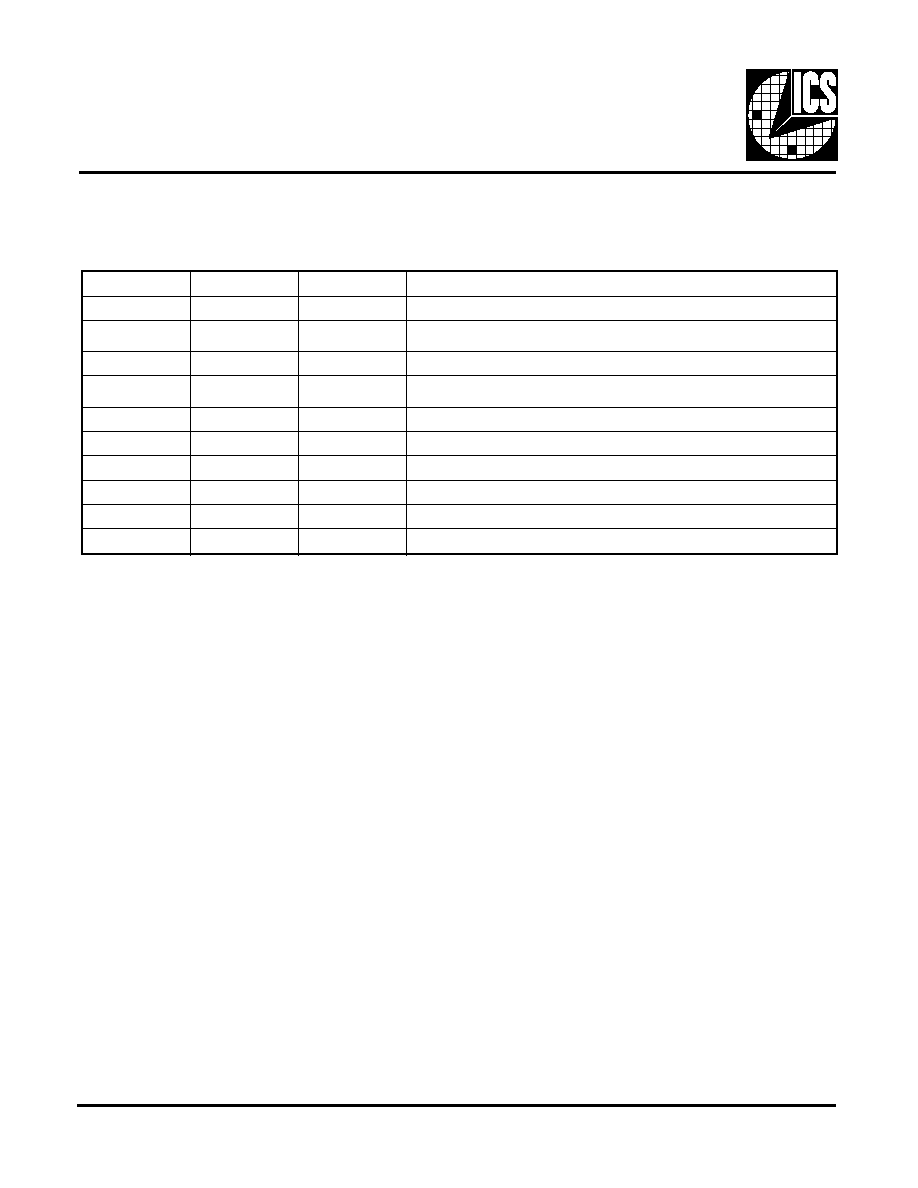
Functionality
VDD=3.0-5.5V, TEMP=0-70∞
PRODUCT PREVIEW documents contain information on products in the formative or
design phase development. Charactersitic data and other specifications are design
goals. ICS reserves the right to change or discontinue these procucts without notice.
Obsolete
ICS9118-02 Obsolete

3
ICS9118-01
ICS9118-02
Obsolete
Absolute Maximum Ratings
*Parameter is guaranteed by design and characterization. Not 100% tested in production.
AVDD, VDD referenced to GND ...................................................................... 7V
Operating temperature under bias ................................................ 0
o
C to +70
o
C
Storage temperature .................................................................. -65
o
C to +150
o
C
Voltage on I/O pins referenced to GND ............... GND -0.5V to VDD +0.5V
Power dissipation ................................................................................... 0.5 Watts
Stresses above those listed under Absolute Maximum Ratings may cause permanent damage to the device. This is a stress
rating only and functional operation of the device at these or any other conditions above those indicated in the operational
sections of the specifications is not implied. Exposure to absolute maximum rating conditions for extended periods may
affect product reliability.
s
c
it
si
r
e
t
c
a
r
a
h
C
C
D
R
E
T
E
M
A
R
A
P
L
O
B
M
Y
S
S
N
O
I
T
I
D
N
O
C
T
S
E
T
N
I
M
P
Y
T
X
A
M
S
T
I
N
U
e
g
a
t
l
o
V
w
o
L
t
u
p
n
I
V
L
I
-
-
8
.
0
V
e
g
a
t
l
o
V
h
g
i
H
t
u
p
n
I
V
H
I
0
.
2
-
-
V
t
n
e
r
r
u
C
w
o
L
t
u
p
n
I
I
L
I
V
N
I
V
0
=
-
0
.
0
1
-
8
1
-
mA
t
n
e
r
r
u
C
h
g
i
H
t
u
p
n
I
I
H
I
V
N
I
V
=
D
D
-
-
0
.
5
mA
e
g
a
t
l
o
V
w
o
L
t
u
p
t
u
O
V
L
O
*
I
L
O
A
m
0
1
+
=
-
5
1
.
0
4
.
0
V
e
g
a
t
l
o
V
h
g
i
H
t
u
p
t
u
O
V
H
O
*
I
H
O
A
m
0
1
-
=
4
.
2
0
.
3
-
V
t
n
e
r
r
u
C
w
o
L
t
u
p
t
u
O
I
L
O
*
V
8
.
0
=
V
0
.
0
2
0
.
5
3
-
A
m
t
n
e
r
r
u
C
h
g
i
H
t
u
p
t
u
O
I
H
O
*
V
4
.
2
=
V
-
0
.
0
2
-
0
.
0
1
-
A
m
t
n
e
r
r
u
C
y
l
p
p
u
S
I
C
C
%
0
1
±
V
3
.
3
=
D
D
V
-
0
.
4
1
0
.
5
2
A
m
e
u
l
a
V
r
o
t
s
i
s
e
R
p
u
-
l
l
u
P
R
u
p
*
-
0
.
0
0
4
0
.
0
0
8
m
h
o
k
s
c
i
t
s
i
r
e
t
c
a
r
a
h
C
C
A
e
m
i
T
e
s
i
R
T
r
*
V
0
.
2
o
t
8
.
0
d
a
o
l
F
p
5
1
-
0
.
1
5
.
1
s
n
e
m
i
T
l
l
a
F
T
f
*
V
8
.
0
o
t
0
.
2
,
d
a
o
l
F
p
5
1
-
0
.
1
5
.
1
s
n
e
m
i
T
k
c
o
L
T
L
*
%
0
8
o
t
%
0
2
,
d
a
o
l
F
p
5
1
0
.
0
1
s
m
e
l
c
y
C
y
t
u
D
D
t
*
;
D
D
V
f
o
%
0
5
@
d
a
o
l
F
p
5
1
T
R
A
U
t
p
e
c
x
E
0
.
5
4
0
.
0
5
0
.
5
5
%
e
l
c
y
C
y
t
u
D
D
t
*
;
D
D
V
f
o
%
0
5
@
d
a
o
l
F
p
5
1
T
R
A
U
t
p
e
c
x
E
0
.
0
4
0
.
5
4
0
.
0
5
%
a
e
m
g
i
S
e
n
O
,
r
e
t
t
i
J
T
s
1
j
*
o
i
d
u
A
0
.
0
5
0
.
0
8
s
p
e
t
u
l
o
s
b
A
,
r
e
t
t
i
J
T
b
a
j
*
o
i
d
u
A
0
.
0
0
3
-
0
.
0
0
3
+
s
p
a
m
g
i
S
e
n
O
,
r
e
t
t
i
J
T
s
1
j
*
T
R
A
U
,
K
L
C
F
E
R
0
.
1
0
.
3
%
e
t
u
l
o
s
b
A
,
r
e
t
t
i
J
T
b
a
j
*
T
R
A
U
,
K
L
C
F
E
R
0
.
5
+
%
y
c
n
e
u
q
e
r
F
n
a
e
M
t
u
p
t
u
O
t
e
g
r
a
T
.
s
v
y
c
a
r
u
c
c
A
F
a
o
*
t
u
p
n
i
z
H
M
0
.
7
2
h
t
i
W
0
.
0
8
-
0
.
0
8
+
m
p
p
e
m
i
T
p
u
-
r
e
w
o
P
T
u
p
*
f
o
g
n
i
s
s
o
r
c
t
s
1
o
t
V
6
.
1
=
D
D
V
m
o
r
F
.
t
c
e
l
e
S
o
i
d
u
A
.
s
m
0
4
<
p
m
a
R
y
l
p
p
u
s
D
D
V
5
.
2
5
.
4
s
m
e
c
n
a
t
i
c
a
p
a
C
t
u
p
n
I
l
a
t
s
y
r
C
C
x
n
i
*
)
1
n
i
P
(
1
X
)
8
n
i
P
(
2
X
0
.
8
1
F
p
Electrical Characteristics at 3.3V
Operating V
DD
= +3.0 V to +3.7V; T
A
= 0 ∫C to 70
o
C unless otherwise stated

5
ICS9118-01
ICS9118-02
Obsolete
Ordering Information
ICS9118M-01
Example:
ICS XXXX M-PPP
Package Type
M =SOIC
Device Type (consists of 3 or 4-digit numbers)
Prefix
ICS, AV=Standard Device
Pattern Number (2 or 3-digit number for parts with ROM code pattern)
14 Pin SOIC Package
PRODUCT PREVIEW documents contain information on products in the formative or
design phase development. Charactersitic data and other specifications are design
goals. ICS reserves the right to change or discontinue these procucts without notice.