 | –≠–ª–µ–∫—Ç—Ä–æ–Ω–Ω—ã–π –∫–æ–º–ø–æ–Ω–µ–Ω—Ç: HI5714 | –°–∫–∞—á–∞—Ç—å:  PDF PDF  ZIP ZIP |

1
January 1998
HI5714
8-Bit, 40/60/75/80 MSPS A/D Converter
Features
∑ Sampling Rate . . . . . . . . . . . . . . . . . . 40/60/75/80 MSPS
∑ Low Power . . . . . . . . . . . . . . . . . . . . . . . . . . . . . .325mW
∑ 7.65 ENOB at 4.43MHz
∑ Overflow/Underflow Three-State TTL Output
∑ Operates with Low Level AC Clock
∑ Very Low Analog Input Capacitance
∑ No Buffer Amplifier Required
∑ No Sample and Hold Required
∑ TTL Compatible I/O
∑ Pin-Compatible to Philips TDA8714
Applications
∑ Video Digitizing
∑ QAM Demodulator
∑ Digital Cable Setup Box
∑ Tape Drive/Mass Storage
∑ Medical Ultrasound Imaging
∑ Communication Systems
Description
The HI5714 is a high precision, monolithic, 8-bit, Analog-to-
Digital Converter fabricated in Intersil' advanced HBC10
BiCMOS process.
The HI5714 is optimized for a wide range of applications such as
ultrasound imaging, mass storage, instrumentation, and video
digitizing, where accuracy and low power consumption are
essential. The HI5714 is offered in 40 MSPS, 60 MSPS, and 75
MSPS sample rates.
The HI5714 delivers
±
0.4 LSB differential nonlinearity while
consuming only 325mW power (Typical) at 75 MSPS. The
digital inputs and outputs are TTL compatible, as well as
allowing for a low-level sine wave clock input.
Pinout
HI5714
(SOIC)
TOP VIEW
Ordering Information
PART
NUMBER
TEMP.
RANGE
(
o
C)
PACKAGE
SAMPLING
FREQUENCY
(MHz)
PKG.
NO.
HI5714/4CB
0 to 70
24 Ld SOIC
40
M24.3
HI5714/6CB
0 to 70
24 Ld SOIC
60
M24.3
HI5714/7CB
0 to 70
24 Ld SOIC
75
M24.3
HI5714/8CB
0 to 70
24 Ld SOIC
80
M24.3
HI5714EVAL
25
Evaluation Board
1
2
3
4
5
6
7
8
9
10
11
12
D1
D0
NC
V
RB
NC
AGND
V
CCA
V
IN
V
RT
NC
O/UF
D7
16
17
18
19
20
21
22
23
24
15
14
13
D2
OE
V
CCO2
OGND
V
CCO1
DGND
D4
D5
D6
D3
V
CCD
CLK
File Number
3973.4
CAUTION: These devices are sensitive to electrostatic discharge; follow proper IC Handling Procedures.
1-888-INTERSIL or 321-724-7143 | Copyright © Intersil Corporation 1999
2
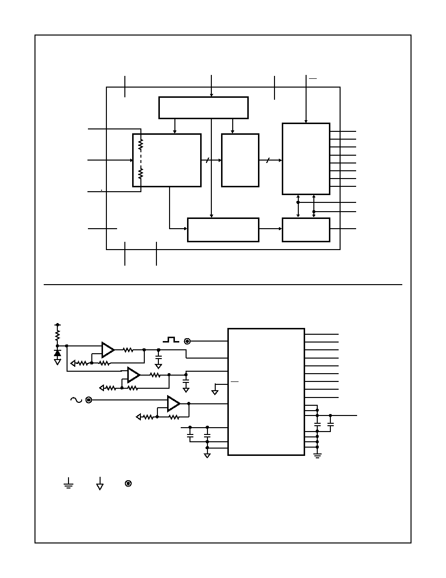
Functional Block Diagram
Typical Application Schematic
NOTES:
1. Pin 5 should be connected to AGND and pins 3 and 10 to DGND to reduce noise coupling into the device.
2. Analog and Digital supplies should be separated and decoupled to reduce digital noise coupling into the analog supply.
ANALOG TO DIGITAL
CONVERTER
LATCHES
TTL OUTPUTS
TTL OUTPUT
OVERFLOW/UNDERFLOW
LATCH
CLOCK DRIVER
V
CCA
CLK
V
CCD
OE
V
RT
V
RB
OGND
AGND
DGND
V
CCO1
V
CCO2
O/UF
V
IN
1
2
4
6
7
8
9
11
12
13
14
15
16
17
18
19
20
21
22
23
24
D7
D6
D5
D4
D3
D2
D1
D0
12
13
14
15
23
24
1
2
V
RB
HI5714
V
RT
CLK
DGND
NC
NC
AGND
V
CCA
V
CCD
D7
D6
D5
D4
D3
D2
D1
D0
as close to part as possible.
1nF and 0.1
µ
F CAPS are placed
CLOCK
V
IN
NC
V
IN
OGND
V
CCO
V
CCO
+5VA
O/UF
BNC
DGND
AGND
OE
11
19
21
18
20
3
17
10
16
9
4
8
7
5
6
22
3.6V
1.3V
+5VA
+5VD
1nF
0.1
µ
F
1nF
0.1
µ
F
0.1
0.1
-
+
-
+
-
+
HI5714
3
Absolute Maximum Ratings
T
A
= 25
o
C
Thermal Information
V
CCA
, V
CCD
, V
CCO
. . . . . . . . . . . . . . . . . . . . . . . . . -0.3V to +6.0V
V
CCA
- V
CCD
. . . . . . . . . . . . . . . . . . . . . . . . . . . . . . . . . . . . . .
0.3V
V
CCO
- V
CCD
. . . . . . . . . . . . . . . . . . . . . . . . . . . . . . . . . . . . . .
0.3V
V
CCA
- V
CCO
. . . . . . . . . . . . . . . . . . . . . . . . . . . . . . . . . . . . . .
0.3V
V
IN
, V
CLK
, V
RT
, V
RB
, OE . . . . . . . . . . . . . . . . . . . . . . -0.3V to +6.0V
I
OUT
, Digital Pins . . . . . . . . . . . . . . . . . . . . . . . . . . . . . . . . . . 10mA
Input Current, All Pins. . . . . . . . . . . . . . . . . . . . . . . . . . . . . . . . 1mA
Digital I/O Pins . . . . . . . . . . . . . . . . . . . . . . . . . . . . OGND to V
CCO
Operating Conditions
Temperature Range
HI5714CB . . . . . . . . . . . . . . . . . . . . . . . . . . . . . . . . . 0
o
C to 70
o
C
Thermal Resistance (Typical, Note 1)
JA
(
o
C/W)
SOIC Package . . . . . . . . . . . . . . . . . . . . . . . . . . . . .
75
Maximum Junction Temperature (Plastic Package) . . . . . . . . 150
o
C
Maximum Storage Temperature Range . . . . . . . . . -65
o
C to 150
o
C
Maximum Lead Temperature (Soldering 10s) . . . . . . . . . . . . . 300
o
C
(SOIC - Lead Tips Only)
CAUTION: Stresses above those listed in "Absolute Maximum Ratings" may cause permanent damage to the device. This is a stress only rating and operation
of the device at these or any other conditions above those indicated in the operational sections of this specification is not implied.
NOTE:
1.
JA
is measured with the component mounted on an evaluation PC board in free air.
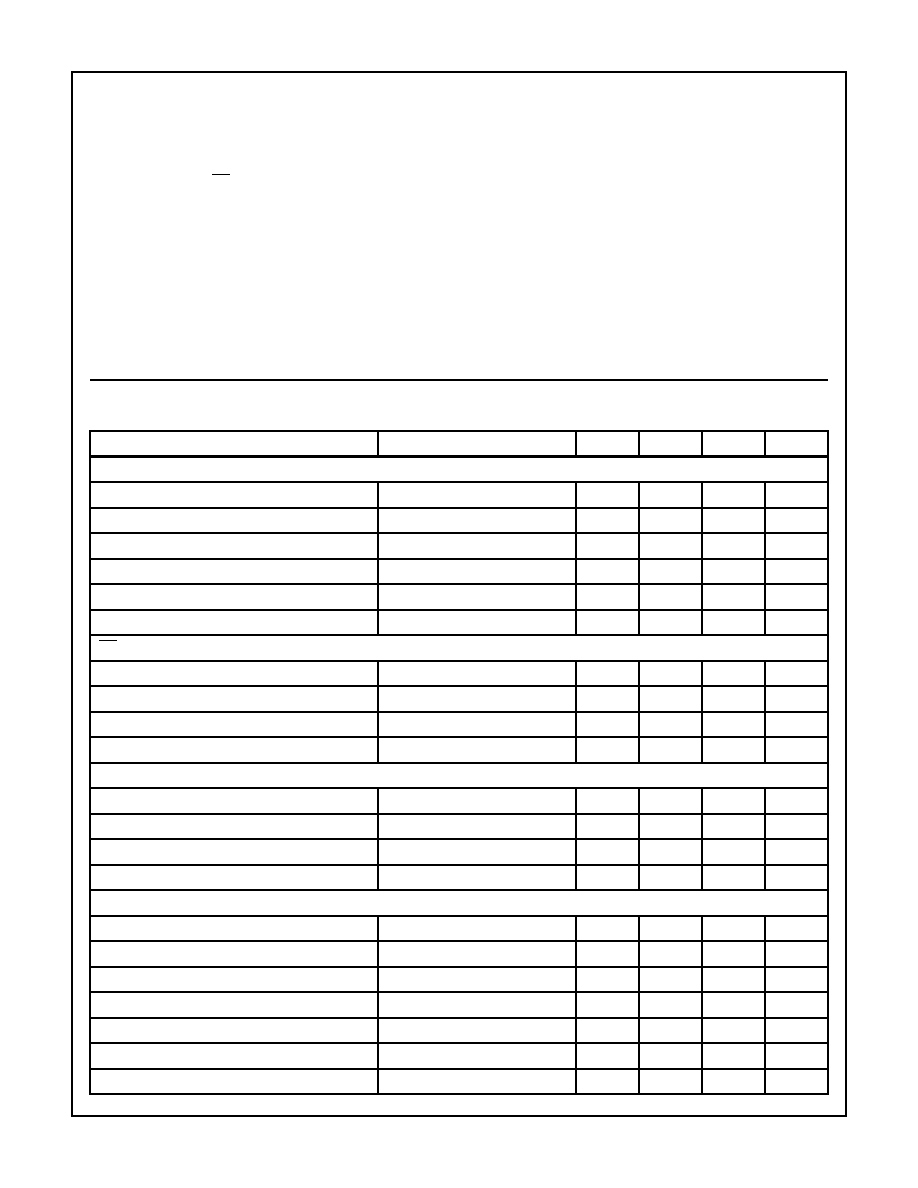
Electrical Specifications
V
CCA
= V
CCD
= V
CCO
= +5V; V
RB
= 1.3V; V
RT
= 3.6V; T
A
= 25
o
C,
Unless Otherwise Specified
PARAMETER
TEST CONDITION
MIN
TYP
MAX
UNITS
CLOCK (Referenced to DGND) (Note 1)
Logic Input Voltage Low, V
IL
0
-
0.8
V
Logic Input Voltage High, V
IH
2.0
-
V
CCD
V
Logic Input Current Low, I
IL
V
CLK
= 0.4V
-400
-
-
µ
A
Logic Input Current High, I
IH
V
CLK
= 2.7V
-
-
300
µ
A
Input Impedance, Z
IN
f
CLK
= 75MHz (Note 8)
-
2
-
k
Input Capacitance, C
IN
f
CLK
= 75MHz (Note 8)
-
4.5
-
pF
OE (Referenced to DGND)
Logic Input Voltage Low, V
IL
0
-
0.8
V
Logic Input Voltage High, V
IH
2.0
-
V
CCD
V
Logic Input Current Low, I
IL
V
IL
= 0.4V
-400
-
-
µ
A
Logic Input Current High, I
IH
V
IH
= 2.7V
-
-
20
µ
A
V
IN
(Referenced to AGND)
Input Current Low, I
IL
V
IN
= 1.2V
-
0
-
µ
A
Input Current High, I
IH
V
IN
= 3.5V
-
100
180
µ
A
Input Impedance, Z
IN
f
IN
= 4.43MHz
-
10
-
k
Input Capacitance, C
IN
f
IN
= 4.43MHz
-
14
-
pF
REFERENCE INPUT
Bottom Reference Range, V
RB
1.2
1.3
1.6
V
Top Reference Range, V
RT
3.5
3.6
3.9
V
Reference Range, V
REF
(V
RT
- V
RB
)
1.9
2.3
2.7
V
Reference Current, I
REF
-
10
-
mA
Reference Ladder Resistance, R
LAD
-
240
-
R
LADTC
-
0.24
-
/
o
C
Bottom Offset Voltage, V
OB
(Note 4)
-
255
-
mV
HI5714
4
V
OBTC
(Note 4)
-
136
-
µ
V/
o
C
Top Offset Voltage, V
OT
(Note 4)
-
-300
-
mV
V
OTTC
(Note 4)
-
480
-
µ
V/
o
C
DIGITAL OUTPUTS (D0 to D7 and O/UF Referenced to OGND)
Logic Output Voltage Low, V
OL
I
O
= 1mA
0
-
0.4
V
Logic Output Voltage High, V
OH
I
O
= -0.4mA
2.7
-
V
CCO
V
Output Leakage Current, I
D
0.4V < V
OUT
< V
CCO
-20
-
+20
µ
A
SWITCHING CHARACTERISTICS (Notes 3, 4) See Figure 9
Sample Rate, f
CLK
HI5714/8
80
-
-
MHz
HI5714/7
75
-
-
MHz
HI5714/6
60
-
-
MHz
HI5714/4
40
-
-
MHz
Clock Pulse Width High, t
CPH
6
-
-
ns
Clock Pulse Width Low, t
CPL
6
-
-
ns
ANALOG SIGNAL PROCESSING (f
CLK
= 40MHz)
Differential Gain, DG
(Notes 5, 8)
-
1.0
-
%
Differential Phase, DP
(Notes 5, 8)
-
0.05
-
degree
HARMONICS (f
CLK
= 75MHz)
Second Harmonic, H2
f
IN
= 4.43MHz
-
-63
-
dB
Third Harmonic, H3
f
IN
= 4.43MHz
-
-65
-
dB
Total Harmonic Distortion, THD
f
IN
= 4.43MHz
-
-59
-
dB
Spurious Free Dynamic Range, SFDR
f
IN
= 4.43MHz
-
62
-
dB
Analog Input Bandwidth (-3dB)
-
18
-
MHz
TRANSFER FUNCTION
Differential Linearity Error, DNL
(Note 6)
-
±
0.4
-
LSB
Integral Linearity Error, INL
(Note 6)
-
±
0.75
-
LSB
EFFECTIVE NUMBER OF BITS
ENOB
HI5714/4 (f
CLK
= 40MHz)
f
IN
= 4.43MHz
-
7.65
-
Bits
f
IN
= 7.5MHz
-
7.5
-
Bits
HI5714/6 (f
CLK
= 60MHz)
f
IN
= 4.43MHz
-
7.65
-
Bits
f
IN
= 7.5MHz
-
7.5
-
Bits
HI5714/7 (f
CLK
= 75MHz)
f
IN
= 4.43MHz
-
7.4
-
Bits
f
IN
= 7.5MHz
-
7.15
-
Bits
f
IN
= 10MHz
-
6.8
-
Bits
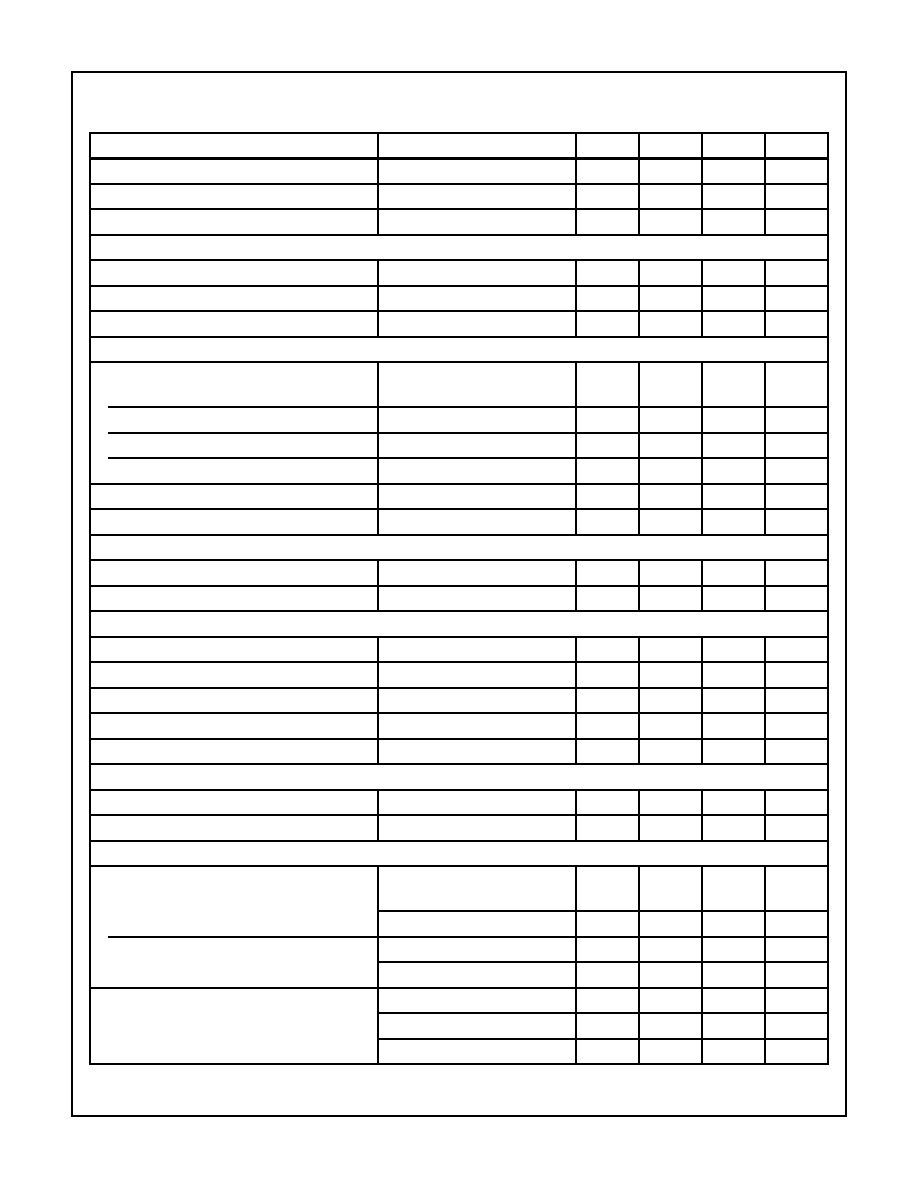
Electrical Specifications
V
CCA
= V
CCD
= V
CCO
= +5V; V
RB
= 1.3V; V
RT
= 3.6V; T
A
= 25
o
C,
Unless Otherwise Specified (Continued)
PARAMETER
TEST CONDITION
MIN
TYP
MAX
UNITS
HI5714
5
HI5714/8 (f
CLK
= 80MHz)
f
IN
= 4.43MHz
-
7.3
-
Bits
f
IN
= 7.5MHz
-
7.0
-
Bits
f
IN
= 10MHz
-
6.64
-
Bits
Bit Error Rate, BER
(Note 7)
-
10
-11
-
Times/
Sample
TIMING (f
CLK
= 75MHz) See Figures 1, 2
Sampling Delay, t
SD
-
-
2
ns
Output Hold Time, t
HD
5
-
-
ns
Output Delay Time, t
D
HI5714/4/6/7
-
10
13
ns
Output Delay Time, t
D
HI5714/8
-
10
12.25
ns
Output Enable Delay, t
PZH
Enable to High
-
14.6
-
ns
Output Enable Delay, t
PZL
Enable to Low
-
17.8
-
ns
Output Disable Delay, t
PHZ
Disable from High
-
5.3
-
ns
Output Disable Delay, t
PLZ
Disable from Low
-
6.7
-
ns
Aperture Jitter, t
AJ
-
50
-
ps
POWER SUPPLY CHARACTERISTICS
Analog Power Supply Range, V
CCA
4.75
5.0
5.25
V
Digital Power Supply Range, V
CCD
4.75
5.0
5.25
V
Output Power Supply Range, V
CCO
4.75
5.0
5.25
V
Total Supply Current
-
65
75
mA
Supply Current, I
CCA
-
30
-
mA
Supply Current, I
CCD
-
26
-
mA
Supply Current, I
CCO
-
9
-
mA
Power Dissipation
-
325
375
mW
NOTES:
1. Dissipation rating assumes device is mounted with all leads soldered to printed circuit board.
2. The supply voltages V
CCA
and V
CCD
may have any value between -0.3V and +6V as long as the difference V
CCA
- V
CCD
lies between
-0.3V and +0.3V.
3. In addition to a good layout of the digital and analog ground, it is recommended that the rise and fall times of the clock not be less than 1ns.
4. Analog input voltages producing code 00 up to and including FF.
V
OB
(Bottom Offset Voltage) is the difference between the analog input which produces data equal to 00 and the Bottom Reference
Voltage (V
RB
).
V
OBTC
(Bottom Offset Voltage Temperature Coefficient) is the variation of V
OB
with temperature.
V
OT
(Top Offset Voltage) is the difference between the Top Reference Voltage (V
RT
) and the analog input which produces data output
equal to FF.
V
OTTC
(Top Offset Voltage Temperature Coefficient) is the variation of V
OT
with temperature.
5. Input is standard 5 step video test signal. A 12-bit R reconstruct DAC and VM700 are used for measurement.
6. Full scale sinewave, f
IN
= 4.43MHz.
7. f
CLK
= 75MHz, f
IN
= 4.43MHz, V
IN
=
±
8 LSB at code 128, 50% Clock duty cycle.
8. Parameter is guaranteed by design, not production tested.
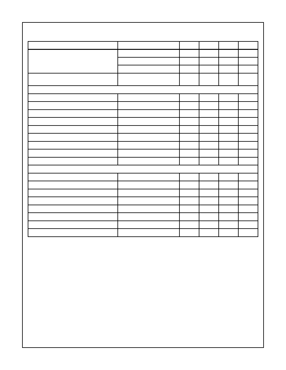
Electrical Specifications
V
CCA
= V
CCD
= V
CCO
= +5V; V
RB
= 1.3V; V
RT
= 3.6V; T
A
= 25
o
C,
Unless Otherwise Specified (Continued)
PARAMETER
TEST CONDITION
MIN
TYP
MAX
UNITS
HI5714
6
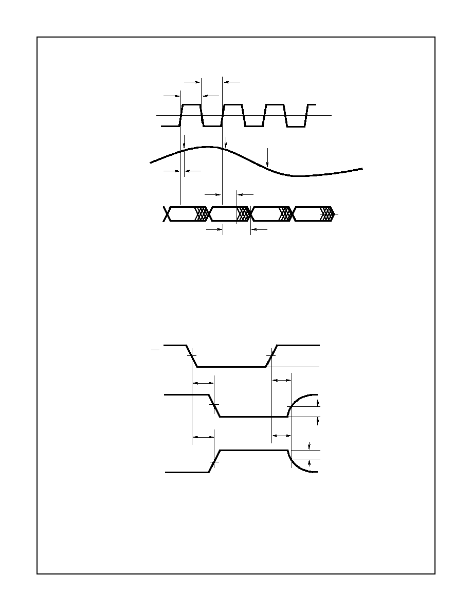
Timing Waveforms
FIGURE 1. INPUT-TO-OUTPUT TIMING
FIGURE 2. THREE-STATE TIMING CIRCUIT
ANALOG
INPUT
CLOCK
INPUT
DATA (D0-D7)
OUTPUTS
t
D
t
DS
t
HD
2.4V
1.4V
0.4V
1.4V
t
CPL
t
CPH
SAMPLE N
SAMPLE N + 1
SAMPLE N + 2
D
N
-
2
D
N
-
1
D
N + 1
D
N
OE
DIGITAL
OUTPUT
DIGITAL
OUTPUT
t
PZL
t
PZH
t
PLZ
t
PHZ
1.4V
1.4V
0V
0V
V
OH
V
OL
0.3V
0.3V
3.5V
INPUT
4V
HI5714

7
Typical Performance Curves
FIGURE 3. TOTAL I
CC
vs TEMPERATURE
FIGURE 4. INTEGRAL LINEARITY ERROR vs TEMPERATURE
FIGURE 5. DIFFERENTIAL LINEARITY ERROR vs
TEMPERATURE
FIGURE 6. REFERENCE RESISTANCE vs TEMPERATURE
FIGURE 7. V
OT
vs TEMPERATURE
FIGURE 8. V
OB
vs TEMPERATURE
70
60
50
40
30
20
10
0
-40 -30
-20 -10
0
10
20
30
40
50
60
70
80
TEMPERATURE (
o
C)
mA
0
-0.1
-0.2
-0.3
-0.4
-0.5
-0.6
-0.7
-0.8
-0.9
-1.0
-40 -30 -20 -10
0
10
20
30
40
50
60
70
80
TEMPERATURE (
o
C)
LSB
90
-0.3
-0.4
-0.5
-0.6
-0.7
-0.8
-0.9
-1.0
-40 -30 -20 -10
0
10
20
30
40
50
60
70
80
TEMPERATURE (
o
C)
LSB
-0.2
-0.1
0
90
270
260
250
240
230
220
210
200
-40 -30 -20
-10
0
10
20
30
40
50
60
70
80
TEMPERATURE (
o
C)
OHMS
280
-230
-240
-250
-260
-270
-280
-290
-320
-40 -30 -20 -10
0
10
20
30
40
50
60
70
80
TEMPERATURE (
o
C)
mV
-220
-300
-310
250
240
230
210
-40 -30 -20 -10
0
10
20
30
40
50
60
70
80
TEMPERATURE (
o
C)
mV
260
220
HI5714
8
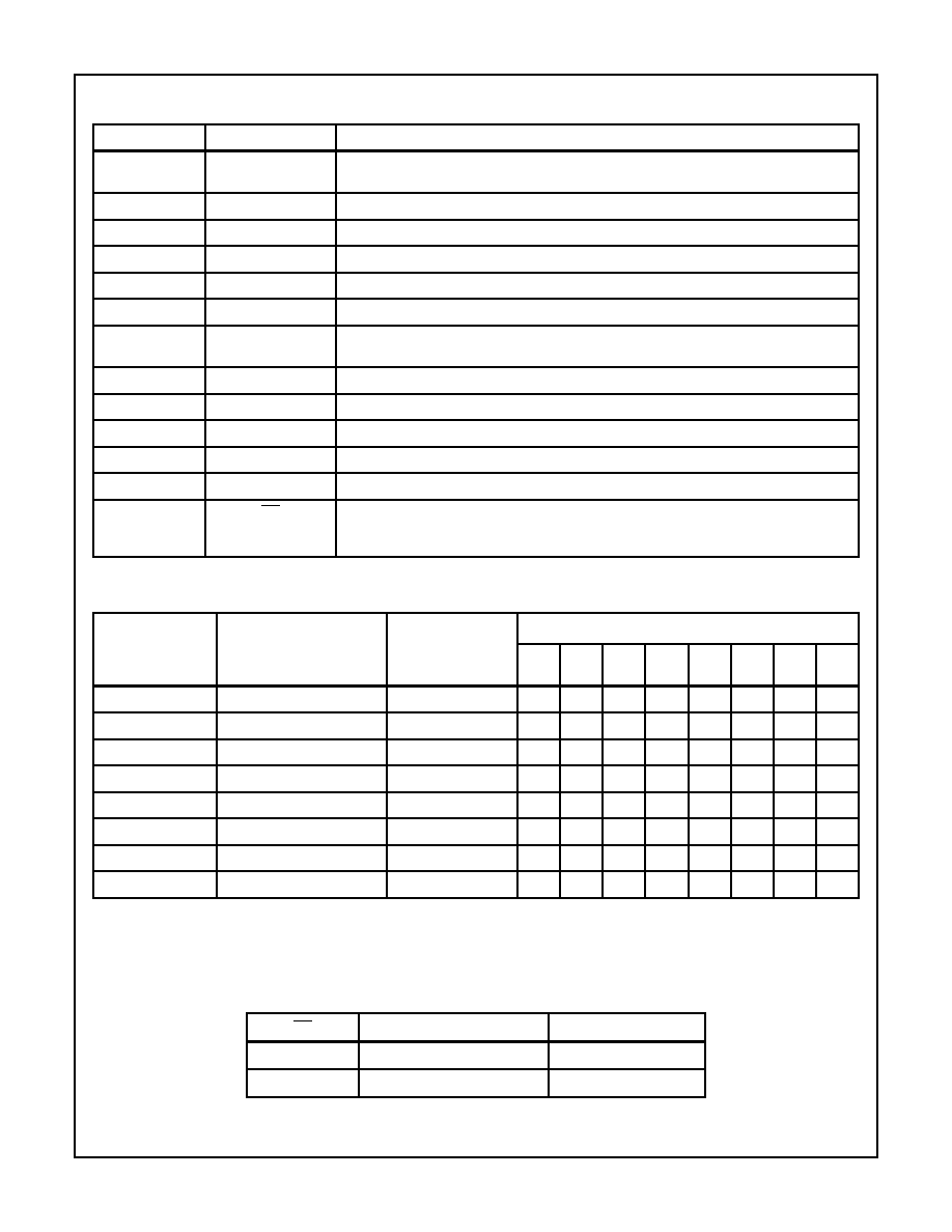
Pin Descriptions
PIN NUMBER
SYMBOL
DESCRIPTION
1, 2, 12-15,
23, 24
D0 to D7
Digital Outputs, D0 (LSB) to D7 (MSB).
4
V
RB
Bottom Reference Voltage Input. Range: 1.2V to 1.6V.
6
AGND
Analog Ground.
7
V
CCA
Analog +5V.
8
V
IN
Analog Input.
9
V
RT
Top Reference Voltage Input. Range: 3.5V to 3.9V.
11
O/UF
Underflow/Overflow Digital Output. Goes high if the analog input goes above or below the
reference (V
RB
, V
RT
) minus the offset.
16
CLK
Clock Input.
17
DGND
Digital GND.
18
V
CCD
Digital +5V.
19, 21
V
CCO1
, V
CCO2
Digital +5V for Digital Output Stage.
20
OGND
Digital Ground for Digital Output Stage.
22
OE
Output Enable
High: Digital outputs are three-stated.
Low: Digital outputs are active.
TABLE 1. A/D CODE TABLE
CODE
DESCRIPTION
(NOTE 1)
INPUT VOLTAGE
V
RT
= 3.6V
V
RB
= 1.3V
O/UF
BINARY OUTPUT CODE
D7
D6
D5
D4
D3
D2
D1
D0
Underflow
<1.555V
1
0
0
0
0
0
0
0
0
0
1.555V
0
0
0
0
0
0
0
0
0
1
-
0
-
-
-
-
-
-
-
-
-
-
0
-
-
-
-
-
-
-
-
-
-
0
-
-
-
-
-
-
-
-
254
-
0
1
1
1
1
1
1
1
0
255
3.300V
0
1
1
1
1
1
1
1
1
Overflow
>3.300V
1
1
1
1
1
1
1
1
1
NOTE:
1. The voltages listed above represent the ideal transition of each output code shown as a function of the reference voltage, including the
typical reference offset voltages.
TABLE 2. MODE SELECTION
OE
D7 to D0
O/UF
1
High Impedance
High Impedance
0
Active: Binary
Active
HI5714

9
Detailed Description
Theory of Operation
The HI5714 design utilizes a folding and interpolating
architecture. This architecture reduces the number of com-
parators, reference taps, and latches, thereby reducing
power requirements, die size and cost.
A folding A/D converter operates basically like a 2 step
subranging converter by using 2 lower resolution converters
to do a course and subranged fine conversion. A more com-
plete description is given in the application note "Using the
HI5714 Evaluation Module" (AN9517).
Reference Input, V
RT
and V
RB
The HI5714 requires an external reference to be connected
to pins 4 and 9, V
RB
and V
RT
.
It is recommended that adequate high frequency decoupling
be provided at the reference input pin in order to minimize
overall converter noise. A 0.1
µ
F and a 1nF capacitor as
close as possible to the reference pins work well.
V
RT
must be kept within the range of 3.5V to 3.9V and V
RB
within 1.2V to 1.6V. If the reference voltages go outside their
respective ranges, the input folding amplifiers may saturate
giving erroneous digital data. The range for (V
RT
- V
RB
) is
1.9V to 2.7V, which defines the analog input range.
Digital Control and Clock Requirements
The HI5714 provides a standard high-speed interface to
external TTL logic families.
The outputs can be three-stated by setting the OE input (pin
22) high.
The clock input operates at standard TTL levels as well as a low
level sine wave around the threshold level. The HI5714 can oper-
ate with clock frequencies from DC to 75MHz. The clock duty
cycle should be 50%
±
10% to ensure rated performance. Duty
cycle variation, within the specified range, has little effect on per-
formance. Due to the clock speed it is important to remember
that clock jitter will affect the quality of the digital output data.
The clock can be stopped at any time and restarted at a later
time. Once restarted the digital data will be valid at the
second rising edge of the clock plus the data delay time.
Digital Outputs and O/UF Output
The digital outputs are standard TTL type outputs. The
HI5714 can drive 1 to 3 TTL inputs depending on the input
current requirements.
Should the analog input exceed the top or bottom reference
the over/underflow output (pin 11) will go high. Should the
analog input exceed the top reference voltage, V
RT
, the
digital outputs will remain at all 1s until the analog input goes
below V
RT
. Also, should the analog input go below the bot-
tom reference voltage, V
RB
, the digital outputs will remain at
all 0s until the analog input goes above V
RT
.
Analog Input
The analog input will accept a voltage within the reference
voltage levels, V
RB
and V
RT
, minus some offset. The offset is
specified in the Electrical Specifications table.
The analog input is relatively high impedance (10k
) but
should be driven from a low impedance source. The input
capacitance is low (14pF) and there is little kickback from the
input, so a series resistance is not necessary but it may help
to prevent the driving amplifier from oscillating.
The input bandwidth is typically 18MHz. Exceeding 18MHz
will result in sparkle at the digital outputs. The bandwidth
remains constant at clock rates up to 75MHz.
Supply and Ground Considerations
In order to keep digital noise out of the analog signal path,
the HI5714 has separate analog and digital supply and
ground pins. The part should be mounted on a board that
provides separate low impedance connections for the analog
and digital supplies and grounds.
The analog and digital grounds should be tied together at
one point near the HI5714. The grounds can be connected
directly, through an inductor (ferrite bead), or a low valued
resistor. DGND and AGND can be tied together. To help min-
imize noise, tie pin 5 (NC) to AGND and pins 3 (NC) and 10
(NC) to DGND.
For best performance, the supplies to the HI5714 should be
driven by clean, linear regulated supplies. The board should
also have good high frequency leaded decoupling capacitors
mounted as close as possible to the converter. Capacitor
leads must be kept as short as possible (less than
1
/
2
inch
total length). A 0.1
µ
F and a 1nF capacitor as close as possi-
ble to the pin works well. Chip capacitors will provide better
high frequency decoupling but leaded capacitors appear to
be adequate.
If the part is to be powered by a single supply, then the
analog supply pins should be isolated by ferrite beads from
the digital supply pins. This should help minimize noise on
the analog power pins.
Refer to Application Note AN9214, "Using Intersil High
Speed A/D Converters", for additional considerations when
using high speed converters.
Increased Accuracy
Further calibration of the ADC can be done to increase
absolute level accuracy. First, a precision voltage equal to
the ideal VIN
-FS
+ 0.5 LSB is applied at V
IN
. Adjust V
RB
until the 0 to 1 transition occurs on the digital output. Next, a
voltage equal to the ideal VIN
+FS
- 1.5 LSB is applied at V
IN
.
V
RT
is then adjusted until the 254 to 255 transition occurs on
the digital output.
Applications
Figures 3 and 4 show two possible circuit configurations, AC
coupled with a DC restore circuit and DC coupled with a DC
offset amplifier.
Due to the high clock rate, FCT (TTL/CMOS) or FAST (TTL)
glue logic should be used. FCT logic will tend to have large
overshoots if not loaded. Long traces (>2 or 3 inches) should
be terminated to maintain signal integrity.
HI5714

10
FIGURE 9. TYPICAL AC COUPLED INPUT WITH DC RESTORE
FIGURE 10. TYPICAL DC COUPLED INPUT
FIGURE 11. 8-BIT VIDEO COMPONENTS
12
13
14
15
23
24
1
2
V
RB
HI5714
V
RT
CLK
DGND
NC
NC
AGND
V
CCA
V
CCD
D7
D6
D5
D4
D3
D2
D1
D0
CLOCK
V
IN
NC
V
IN
OGND
V
CCO
V
CCO
+5VA
O/UF
OE
11
19
21
18
20
3
17
10
16
9
4
8
7
5
6
22
3.6V
1.3V
+5VA
+5VD
10
0.1
10
0.1
0.1
0.1
SAMPLE
PULSE
DC RESTORE
-
+
-
+
12
13
14
15
23
24
1
2
V
RB
HI5714
V
RT
CLK
DGND
NC
NC
AGND
V
CCA
V
CCD
D7
D6
D5
D4
D3
D2
D1
D0
CLOCK
V
IN
NC
V
IN
OGND
V
CCO
V
CCO
+5VA
O/UF
OE
11
19
21
18
20
3
17
10
16
9
4
8
7
5
6
22
3.6V
1.3V
+5VA
+5VD
10
0.1
10
0.1
0.1
0.1
+5VA
OFFSET
-
+
-
+
-
+
A/D
D/A
DSP/
µ
P
REFERENCE
ICL8069
AMP
AMP
HA5020 (Single)
HA5022 (Dual)
HA5024 (Quad)
HA5013 (Triple)
HFA1105 (Single)
HFA1205 (Dual)
HFA1405 (Quad)
HI5714 (8-Bit)
HSP9501
HSP48410
HSP48908
HSP48901
HSP48212
HSP43881
HSP43168
HI1171 (8-Bit)
CA3338 (8-Bit)
HI5721 (10-Bit)
HA5020 (Single)
HA2842 (Single)
HFA1115 (Single)
HFA1212 (Dual)
HFA1412 (Quad)
CMOS Logic Available in FCT
HSP9501: Programmable Data Buffer
HSP48410: Histogrammer/accumulating Buffer, 10-Bit Pixel Resolution, 4K x 4K Frame Size
HSP48908: 2-D Convolver, 3 x 3 Kernal Convolution, 8-Bit
HSP48901: 3 x 3 Image Filter, 30MHz, 8-Bit
HSP48212: Video Mixer
HSP43881: Digital Filter, 30MHz, 1-D and 2-D Fir Filters
HSP43168: Dual Fir Filter, 10-Bit, 33/45MHz
HI3050 (10-Bit)
HI5714

11
Timing Definitions
Aperture Delay: Aperture delay is the time delay between
the external sample command (the rising edge of the clock)
and the time at which the signal is actually sampled. This
delay is due to internal clock path propagation delays.
Aperture Jitter: This is the RMS variation in the aperture
delay due to variation of internal clock path delays.
Data Latency
After the analog sample is taken, the data on the bus is out-
put at the next rising edge of the clock. This is due to the out-
put latch of the converter. This delay is specified as the data
latency. After the data latency time, the data representing
each succeeding sample is output at the following clock
pulse. The digital data lags the analog input by 1 cycle.
Static Performance Definitions
Offset Error and Full-Scale Error use a measured value of
the external voltage reference to determine the ideal plus
and minus full-scale values. The results are all displayed in
LSBs.
Bottom Offset Voltage (V
OB
)
The first code transition should occur at a level 0.5 LSB
above the negative full-scale. Bottom offset voltage is
defined as the deviation of the actual code transition from
this point.
Top Offset Voltage (V
OT
)
The last code transition should occur for a analog input that
is 1.5 LSBs below positive full-scale. Top Offset Voltage is
defined as the deviation of the actual code transition from
this point.
Differential Linearity Error (DNL)
DNL is the worst case deviation of a code width from the
ideal value of 1 LSB. The converter is guaranteed to have no
missing codes.
Integral Linearity Error (INL)
INL is the worst case deviation of a code center from a best
fit straight line calculated from the measured data.
Dynamic Performance Definitions
Fast Fourier Transform (FFT) techniques are used to evalu-
ate the dynamic performance of the HI5714. A low distortion
sine wave is applied to the input, it is sampled, and the out-
put is stored in RAM. The data is then transformed into the
frequency domain with a 2048 point FFT and analyzed to
evaluate the dynamic performance of the A/D. The sine wave
input to the part is 0.5dB down from full scale for these tests.
The distortion numbers are quoted in dBc (decibels with
respect to carrier) and DO NOT include any correction fac-
tors for normalizing to full scale.
Signal-to-Noise Ratio (SNR)
SNR is the measured RMS signal to RMS noise at a speci-
fied input and sampling frequency. The noise is the RMS
sum of all of the spectral components except the fundamen-
tal and the first five harmonics.
Signal-to-Noise + Distortion Ratio (SINAD)
SINAD is the measured RMS signal to RMS sum of all other
spectral components below the Nyquist frequency excluding
DC.
Effective Number Of Bits (ENOB)
The effective number of bits (ENOB) is derived from the
SINAD data. ENOB is calculated from:
ENOB = (SINAD - 1.76) / 6.02
2nd and 3rd Harmonic Distortion
This is the ratio of the RMS value of the 2nd and 3rd
harmonic component respectively to the RMS value of the
measured input signal.
Full Power Input Bandwidth
Full power bandwidth is the frequency at which the ampli-
tude of the digitally reconstructed output has decreased 3dB
below the amplitude of the input sine wave. The input sine
wave has a peak-to-peak amplitude equal to the difference
between the top reference voltage input and the bottom ref-
erence voltage input. The bandwidth given is measured at
the specified sampling frequency.
HI5714

12
Die Characteristics
DIE DIMENSIONS:
134 mils x 134 mils x 19 mils
±
1 mil
METALLIZATION:
Type: AlSiCu
Thickness: M1 - 8k
≈
, M2 - 17k
≈
SUBSTRATE POTENTIAL (Powered Up):
GND (0.0V)
PASSIVATION:
Type:
Sandwich Passivation*
Undoped Silicon Glass (USG) + Nitride
Thickness: USG - 8k
≈
, Nitride - 4.2k
≈
Total 12.2k
≈
+ 2k
≈
WORST CASE CURRENT DENSITY:
1.6 x 10
4
A/cm
2
TRANSISTOR COUNT:
3714
DIE ATTACH:
Silver Filled Epoxy
Metallization Mask Layout
HI5714
DO
D1
D2
D3
OE
O/UF
D7
D6
D5
D4
V
RB
AGND
V
CCA
V
RT
V
IN
V
CC02
OGND
V
CC01
DGND
V
CCD
CLK
HI5714

13
HI5714
Small Outline Plastic Packages (SOIC)
INDEX
AREA
E
D
N
1
2
3
-B-
0.25(0.010)
C A
M
B S
e
-A-
L
B
M
-C-
A1
A
SEATING PLANE
0.10(0.004)
h x 45
o
C
H
0.25(0.010)
B
M
M
NOTES:
1. Symbols are defined in the "MO Series Symbol List" in Section 2.2 of
Publication Number 95.
2. Dimensioning and tolerancing per ANSI Y14.5M-1982.
3. Dimension "D" does not include mold flash, protrusions or gate burrs.
Mold flash, protrusion and gate burrs shall not exceed 0.15mm
(0.006 inch) per side.
4. Dimension "E" does not include interlead flash or protrusions. Inter-
lead flash and protrusions shall not exceed 0.25mm (0.010 inch) per
side.
5. The chamfer on the body is optional. If it is not present, a visual index
feature must be located within the crosshatched area.
6. "L" is the length of terminal for soldering to a substrate.
7. "N" is the number of terminal positions.
8. Terminal numbers are shown for reference only.
9. The lead width "B", as measured 0.36mm (0.014 inch) or greater
above the seating plane, shall not exceed a maximum value of
0.61mm (0.024 inch)
10. Controlling dimension: MILLIMETER. Converted inch dimensions
are not necessarily exact
M24.3
(JEDEC MS-013-AD ISSUE C)
24 LEAD WIDE BODY SMALL OUTLINE PLASTIC PACKAGE
SYMBOL
INCHES
MILLIMETERS
NOTES
MIN
MAX
MIN
MAX
A
0.0926
0.1043
2.35
2.65
-
A1
0.0040
0.0118
0.10
0.30
-
B
0.013
0.020
0.33
0.51
9
C
0.0091
0.0125
0.23
0.32
-
D
0.5985
0.6141
15.20
15.60
3
E
0.2914
0.2992
7.40
7.60
4
e
0.05 BSC
1.27 BSC
-
H
0.394
0.419
10.00
10.65
-
h
0.010
0.029
0.25
0.75
5
L
0.016
0.050
0.40
1.27
6
N
24
24
7
0
o
8
o
0
o
8
o
-
Rev. 0 12/93
All Intersil semiconductor products are manufactured, assembled and tested under ISO9000 quality systems certification.
Intersil products are sold by description only. Intersil Corporation reserves the right to make changes in circuit design and/or specifications at any time without
notice. Accordingly, the reader is cautioned to verify that data sheets are current before placing orders. Information furnished by Intersil is believed to be accurate
and reliable. However, no responsibility is assumed by Intersil or its subsidiaries for its use; nor for any infringements of patents or other rights of third parties which
may result from its use. No license is granted by implication or otherwise under any patent or patent rights of Intersil or its subsidiaries.
For information regarding Intersil Corporation and its products, see web site http://www.intersil.com