12/03/04
International Rectifier
· 233 Kansas Street, El Segundo, CA 90245 USA
R
R
E
E
F
F
E
E
R
R
E
E
N
N
C
C
E
E
D
D
E
E
S
S
I
I
G
G
N
N
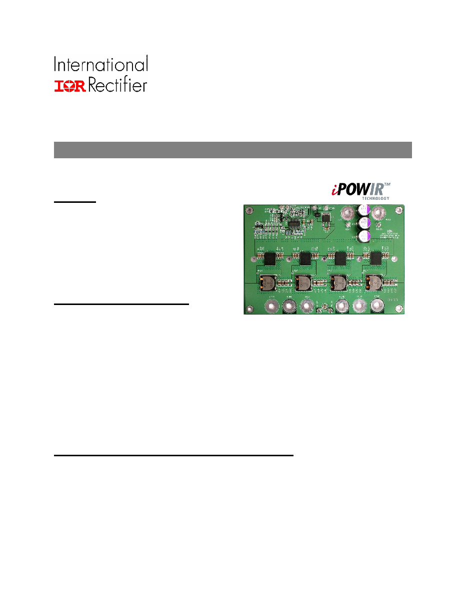
IRDCiP2003A-C
IRDCiP2003A-C: 1MHz, 160A, Synchronous Buck
Converter Using iP2003A
Overview
This reference design is capable of delivering up to a current of
160A with the enclosed heatsink attached at an ambient
temperature of 60ºC with 400LFM or an ambient temperature of
45ºC with 200LFM of airflow. Performance graphs and waveforms
are provided in figures 19. The figures and table in pages 5 8
are provided as a reference design to enable engineers to very
quickly and easily design a 4-phase converter. Refer to the data
sheet for the controller listed in the bill of materials in order to
optimize this design to your specific requirements. A variety of other
controllers may also be used, but the design will require layout and
control circuit modifications.
Demoboard Quick Start Guide
Initial Settings:
The output is set to 1.3V, but can be adjusted from 0.8V to 3.3V by changing the voltage divider values of R3 and R32 according
to the following formula:
R3 = R32 = (24.9k x 0.8) / (VOUT - 0.8)
The switching frequency per phase is set to 1MHz with the frequency set resistor R4. This creates an effective output frequency of
4MHz. The graph in figure 11 shows the relationship between R4 and the switching frequency per phase. The frequency may be
adjusted by changing R4 as indicated; however, extreme changes from the 1MHz set point may require redesigning the control
loop and adjusting the values of input and output capacitors. Refer to the SOA graph in the iP2003A datasheet for maximum
operating current at different conditions.
Procedure for Connecting and Powering Up Demoboard:
1. Apply input voltage across (+12V) across VIN and PGND.
2. Apply load across VOUT pads and PGND pads.
3. Adjust load to desired level. See recommendations below.
IRDCiP2003A-C Recommended Operating Conditions
(refer to the iP2003A datasheet for maximum operating conditions)
Input voltage:
5V - 12V
1
Output voltage:
0.8 - 3.3V
Switching Freq:
1MHz per phase, 4MHz effective output frequency.
Output current:
This reference design is capable of delivering up to 160A with the enclosed heatsink attached, at an
ambient temperature of 60ºC with 400LFM of airflow, or an ambient temperature of 45ºC with 200LFM of
airflow.
1
Note: If Vin = 5V, then connect Vin to test point TP3 and Terminal T1 and remove jumper J1. Refer to schematic for details.
Additionally, the threshold of the POR circuit should be adjusted to allow the supply to sequence properly.
IRDCiP2003A-C_ ____ _____
www.irf.com 2
0.0
5.0
10.0
15.0
20.0
25.0
30.0
35.0
40.0
45.0
50.0
55.0
0
20
40
60
80
100
120
140
160
Output Current (A)
Pow
e
r
L
o
s
s
(
W
)
70%
71%
72%
73%
74%
75%
76%
77%
78%
79%
80%
81%
82%
83%
84%
85%
86%
0
20
40
60
80
100
120
140
160
Output Current (A)
E
f
f
i
ci
en
cy
(
%
)
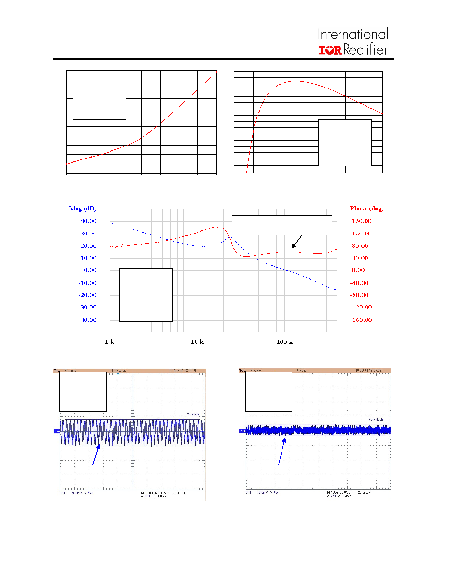
Fig. 1: Power Loss vs. Current
Fig. 2: Efficiency vs. Current
Fig. 3: Bode Plot
Fig. 4: Input Voltage Ripple Waveform
Fig. 5: Output Voltage Ripple Waveform
V
IN
= 12V
V
OUT
= 1.3V
f
SW
= 1MHz
T
A
= 25
°C
V
IN
= 12V
V
OUT
= 1.3V
f
SW
= 1MHz
T
A
= 25
°C
V
IN
= 12V
V
OUT
= 1.3V
I
OUT
= 160A
f
SW
= 1MHz
T
A
= 25
°C
Ripple = 90mVp-p
Ripple = 7.0mVp-p
Phase Margin = 61
°
Cross-Over Freq. = 106kHz
V
IN
= 12V,
V
OUT
= 1.3V
I
OUT
= 160A,
f
SW
= 1MHz
T
A
= 25
°C
V
IN
= 12V,
V
OUT
= 1.3V
I
OUT
= 160A,
f
SW
= 1MHz
T
A
= 25
°C
_____________ __IRDCiP2003A-C
3
www.irf.com
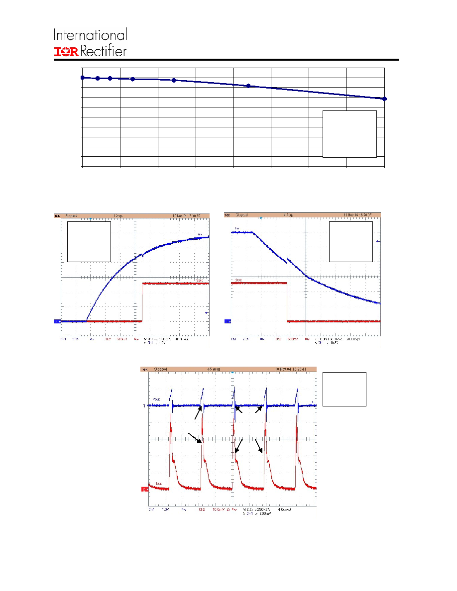
98.0%
98.2%
98.4%
98.6%
98.8%
99.0%
99.2%
99.4%
99.6%
99.8%
100.0%
0
20
40
60
80
100
120
140
160
Output Current (A)
O
u
tput Vol
t
age
Ac
cu
r
acy
(%
)
Fig. 6: Output Voltage Accuracy vs. Current
Fig. 7: Power Up Waveform
Fig. 8: Power Down Waveform
Fig. 9: Short Circuit Condition Waveform
V
IN
= 12V
V
OUT
= 1.3V
f
SW
= 1MHz
T
A
= 25
°C
V
IN
= 12V
V
OUT
= 1.3V
I
OUT
= 160A
f
SW
= 1MHz
T
A
= 25
°C
V
IN
= 12V
V
OUT
= 1.3V
I
OUT
= 160A
f
SW
= 1MHz
T
A
= 25
°C
Ch. 1: V
IN
2V/div
Ch. 2: V
OUT
0.5V/div
Ch. 1: V
IN
2V/div
Ch. 2: V
OUT
0.5V/div
Ch. 1: V
OUT
1V/div
Ch. 2: I
OUT
50A/div
V
IN
= 12V
V
OUT
= 1.3V
f
SW
= 1MHz
T
A
= 25
°C
Short
circuit at
start-up
Hiccups
until short
circuit is
removed
IRDCiP2003A-C_ ____ _____
www.irf.com 4
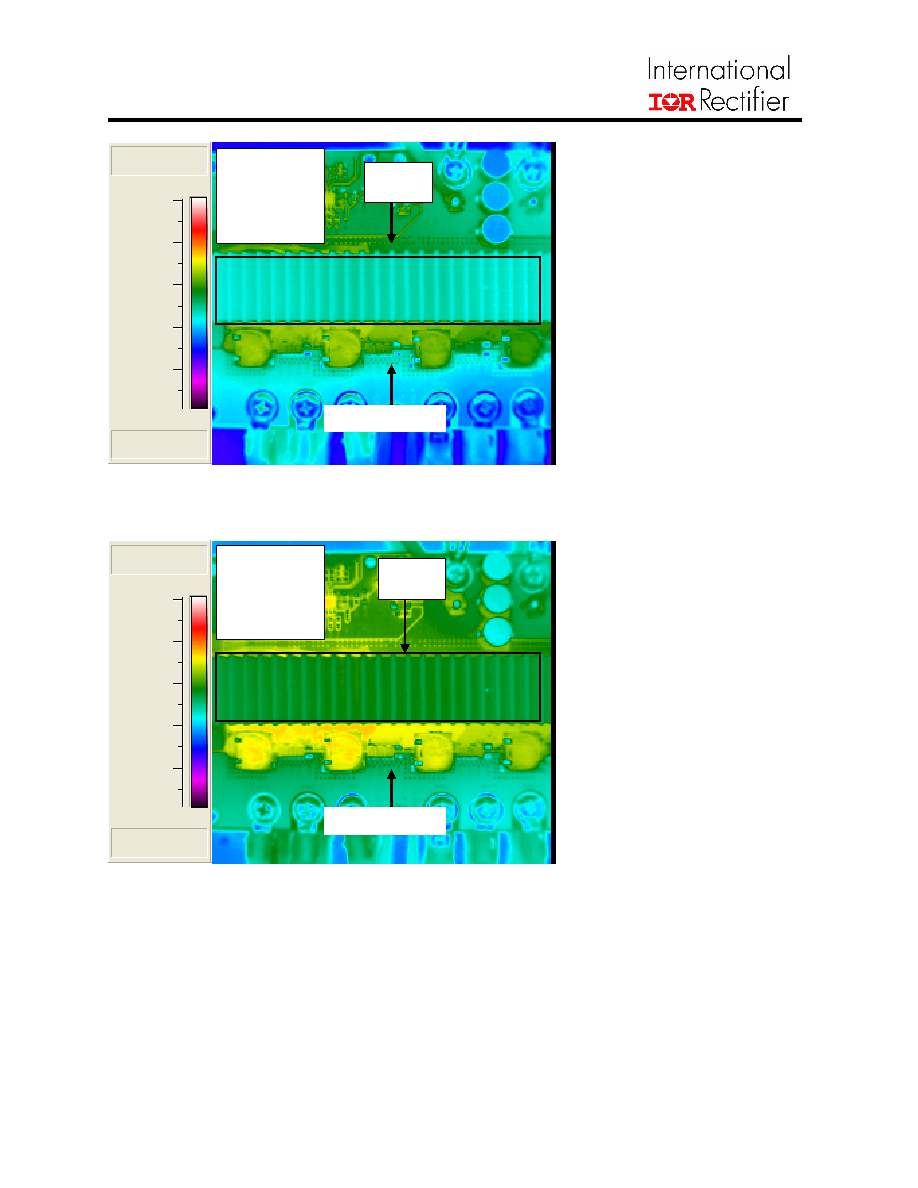
Board Temperature @ 1mm
from edge of module:
T
PCB
(U2): 83.4
°C
T
PCB
(U3): 82.7
°C
T
PCB
(U4): 82.3
°C
T
PCB
(U5): 79.2
°C
Board Temperature @ 1mm
from edge of module:
T
PCB
(U2): 88.9
°C
T
PCB
(U3): 87.5
°C
T
PCB
(U4): 87.3
°C
T
PCB
(U5): 85.1
°C
Fig. 10: Thermal Images With Board and Heatsink Temperatures
*>120.0°C
*<21.3°C
40.0
60.0
80.0
100.0
120.0
*>120.0°C
*<21.3°C
40.0
60.0
80.0
100.0
120.0
V
IN
= 12V
V
OUT
= 1.3V
I
OUT
= 160A
f
SW
= 1MHz
T
A
= 45
°C
Airflow = 200LFM
Max
70.7
°C
Max
78.5
°C
V
IN
= 12V
V
OUT
= 1.3V
I
OUT
= 160A
f
SW
= 1MHz
T
A
= 60
°C
Airflow = 400LFM
Airflow direction
Airflow direction
_____________ __IRDCiP2003A-C
5
www.irf.com
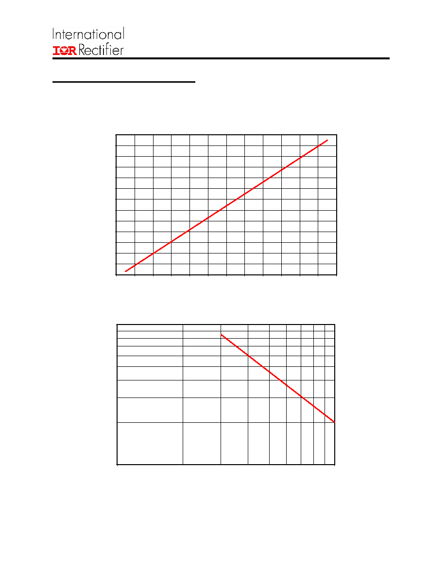
Adjusting the Over-Current Limit
R5, R7, R8, and R9 are the resistors used to adjust the over-current trip point. The trip point is a function of the controller and
corresponds to the per phase output current indicated on the x-axis of Fig. 11. For example, selecting 3.65k resistors will set the
trip point of each phase to 66A. (Note: Fig. 11 is based on iP2003A, TJ = 125
°
C. The trip point will be higher than expected if the
reference board is cool and is being used for short circuit testing.)
2.4
2.5
2.6
2.7
2.8
2.9
3.0
3.1
3.2
3.3
3.4
3.5
3.6
3.7
43
45
47
49
51
53
55
57
59
61
63
65
67
Over-Current Trip Point (per Phase)
R
ISEN
(k
)
Fig. 11: R
ISEN
vs. Current (per Phase)
10
100
100
1000
Output Frequency (kHz) (per Phase)
R4 (
k
)
Fig. 12: R4 vs. Frequency (per Phase)