 | ÐлекÑÑоннÑй компоненÑ: IRK.166 | СкаÑаÑÑ:  PDF PDF  ZIP ZIP |
Äîêóìåíòàöèÿ è îïèñàíèÿ www.docs.chipfind.ru
165 A
195 A
230 A
Bulletin I27116 rev. C 03/02
1
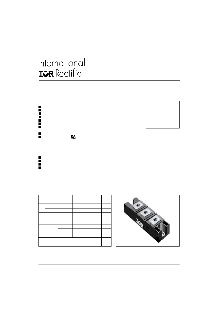
NEW INT-A-pak Power Modules
I
F(AV)
165
195
230
A
@ T
C
100
100
100
°C
I
F(RMS)
260
305
360
A
I
FSM
@ 50Hz
4000
4750
5500
A
@ 60Hz
4200
4980
5765
A
I
2
t @ 50Hz
80
113
151
KA
2
s
@ 60Hz
73
103
138
KA
2
s
I
2
t
798
1130
1516
KA
2
s
V
RRM
400 to 1600
V
T
J
range
- 40 to 150
°C
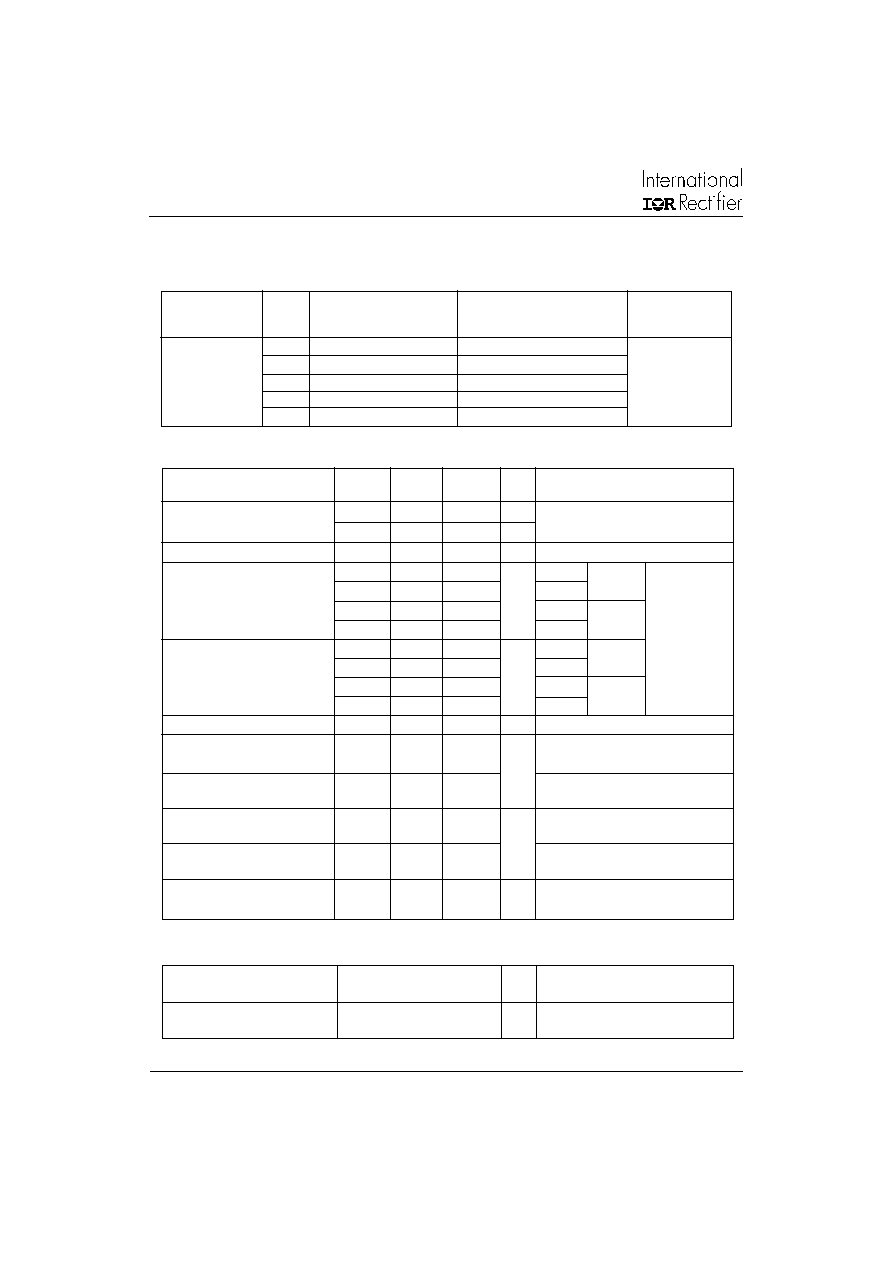
Major Ratings and Characteristics
Features
High Voltage
Electrically Isolated by DBC Ceramic ( Al
2
O
3
)
3500 V
RMS
Isolating Voltage
Industrial Standard Package
High Surge Capability
Glass Passivated Chips
Modules uses High Voltage Power diodes
in four Basic Configurations
Simple Mounting
UL E78996 approved
Parameters
IRK.166.. IRK.196.. IRK.236.. Units
STANDARD RECOVERY DIODES
Applications
DC Motor Control and Drives
Battery Charges
Welders
Power Converters
SERIES
IRK.166, .196, .236
CASE STYLE NEW INT-A-PAK
www.irf.com
IRK.166, .196, .236 Series
2
Bulletin I27116 rev. C 03/02
www.irf.com
I
RRM
Maximum peak reverse and
20
mA
T
J
= 150
o
C
off-state leakage current
V
INS
RMS isolation voltage
3500
V
50Hz, circuit to base, all terminals shorted,
t = 1s
I
F(AV)
Max. average on-state current
165
195
230
A
180° conduction, half sine wave
@ Case temperature
100
100
100
°C
I
F(RMS)
Max. RMS on-state current
260
305
360
A
I
FSM
Maximum peak, one-cycle
4000
4750
5500
A
t = 10ms No voltage
on-state, non-repetitive
4200
4980
5765
t = 8.3ms reapplied
surge current
3350
4000
4630
t = 10ms 100% V
RRM
3500
4200
4850
t = 8.3ms reapplied
Sine half wave,
I
2
t
Maximum I
2
t for fusing
80
113
151
KA
2
s
t = 10ms No voltage
Initial T
J
= T
J
max.
73
103
138
t = 8.3ms reapplied
56
80
107
t = 10ms 100% V
RRM
52
73
98
t = 8.3ms reapplied
I
2
t
Maximum I
2
t for fusing
798
1130
1516
KA
2
s t = 0.1 to 10ms, no voltage reapplied
V
F(TO)1
Low level value of threshold
0.73
0.69
0.7
V
(16.7% x
x I
F(AV)
< I <
x I
F(AV)
), @ T
J
max.
voltage
V
F(TO)2
High level value of threshold
0.88
0.78
0.83
(I >
x I
F(AV)
), @ T
J
max.
voltage
r
t1
Low level value on-state
1.5
1.3
1.2
m
(16.7% x
x I
F(AV)
< I <
x I
F(AV)
), @ T
J
max.
slope resistance
r
t2
High level value on-state
1.26
1.2
1.07
(I >
x I
F(AV)
), @ T
J
max.
slope resistance
V
FM
Maximum forward voltage drop
1.43
1.38
1.46
V
I
FM
=
x I
F(AV)
, T
J
= 25°C, 180°conduction
Av. power = V
F(TO)
x I
F(AV)
+ r
f
x (I
F(RMS)
)
2
Parameter
IRK.166 IRK.196 IRK.236 Units Conditions
Forward Conduction
Blocking
Electrical Specifications
Voltage Ratings
Type number
Voltage V
RRM
, Maximum repetitive V
RSM
, Maximum non-repetitive
I
RRM
Code
peak reverse voltage
peak reverse voltage
150°C
V
V
m A
IRK.166
04
400
500
20
IRK.196
08
800
900
IRK.236
12
1200
1300
14
1400
1500
16
1600
1700
IRK.166, .196, .236 Series
3
Bulletin I27116 rev. C 03/02
www.irf.com
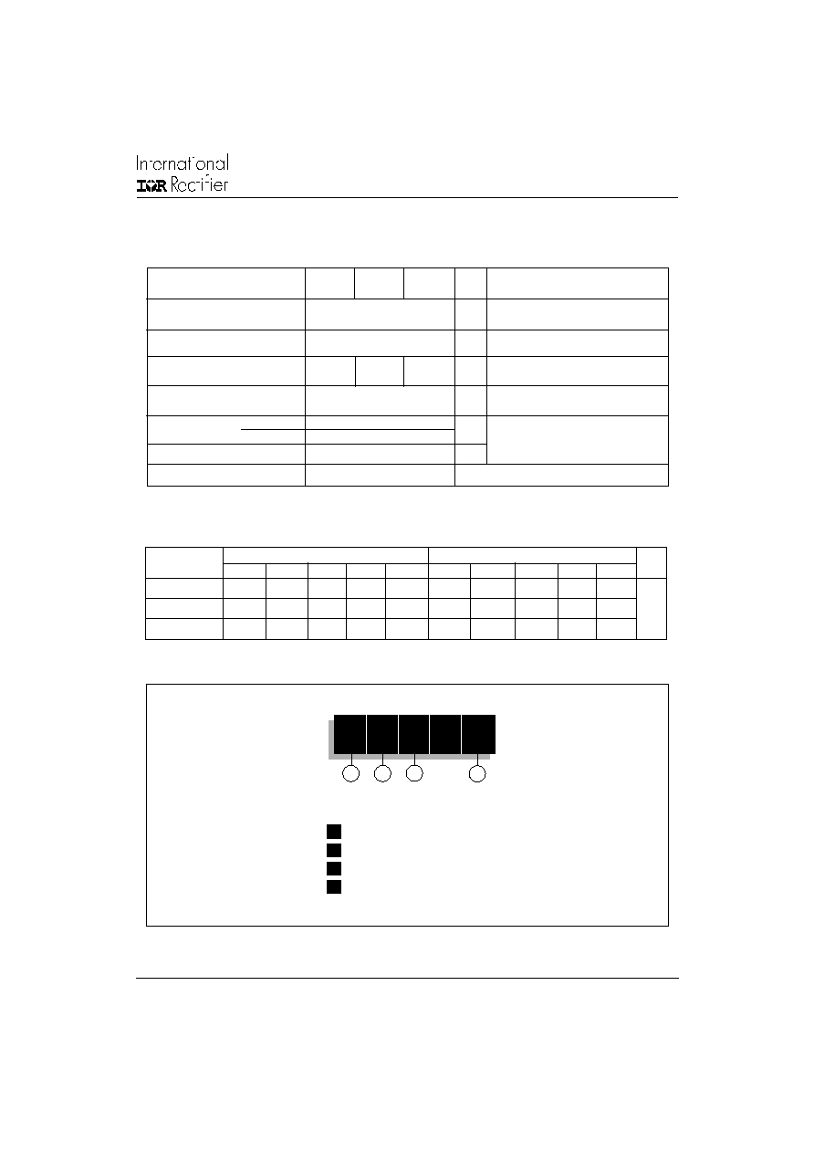
Thermal and Mechanical Specifications
T
J
Max. junction operating
-40 to 150
°C
temperature range
T
stg
Max. storage temperature
-40 to 150
°C
range
R
thJC
Max. thermal resistance,
0.2
0.16
0.14
K/W
DC operation, per junction
junction to case
R
thCS
Max. thermal resistance,
0.05
K/W
Mounting surface smooth, flat and greased
case to heatsink
Per module
T
Mounting
IAP to heatsink
4 to 6
Nm
torque ± 10%
busbar to IAP
4 to 6
wt
Approximate weight
200 (7.1)
g (oz)
Case Style
New Int-A-Pak
A mounting compound is recommended and
the
torque should be rechecked after a
period of 3 hours to allow for the spread of the
compound. Lubricated threads.
Parameter
IRK.166
IRK.196
IRK.236
Units Conditions
Sinusoidal conduction @ T
J
max.
Rectangular conduction @ T
J
max.
Devices
Units
180
o
120
o
90
o
60
o
30
o
180
o
120
o
90
o
60
o
30
o
IRK.166
0.025
0.03
0.038
0.055
0.089
0.018
0.031
0.041
0.057
0.089
IRK.196
0.016
0.019
0.024
0.034
0.053
0.012
0.02
0.026
0.035
0.054 K/W
IRK.236
0.009
0.010
0.014
0.018
0.025
0.008
0.012
0.015
0.019
0.025
R Conduction (per Junction)
(The following table shows the increment of thermal resistance R
thJC
when devices operate at different conduction angles than DC)
1
2
3
1
-
Module Type
2
-
Circuit Configuration
3
-
Current Rating: I
F(AV)
4
-
Voltage Code: Code x 100 = V
RRM
4
Device Code
Ordering Information Table
IRK
D
236
/
16
IRK.166, .196, .236 Series
4
Bulletin I27116 rev. C 03/02
www.irf.com
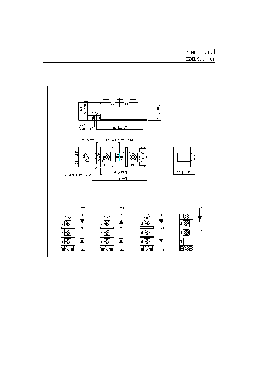
Outline Table
Dimensions are in millimeters and [inches]
NOTE: To order the Optional Hardware see Bulletin I27900
IRKD
IRKC
IRKJ
IRKE
1
2
3
1
2
3
1
2
3
1
2
IRK.166, .196, .236 Series
5
Bulletin I27116 rev. C 03/02
www.irf.com
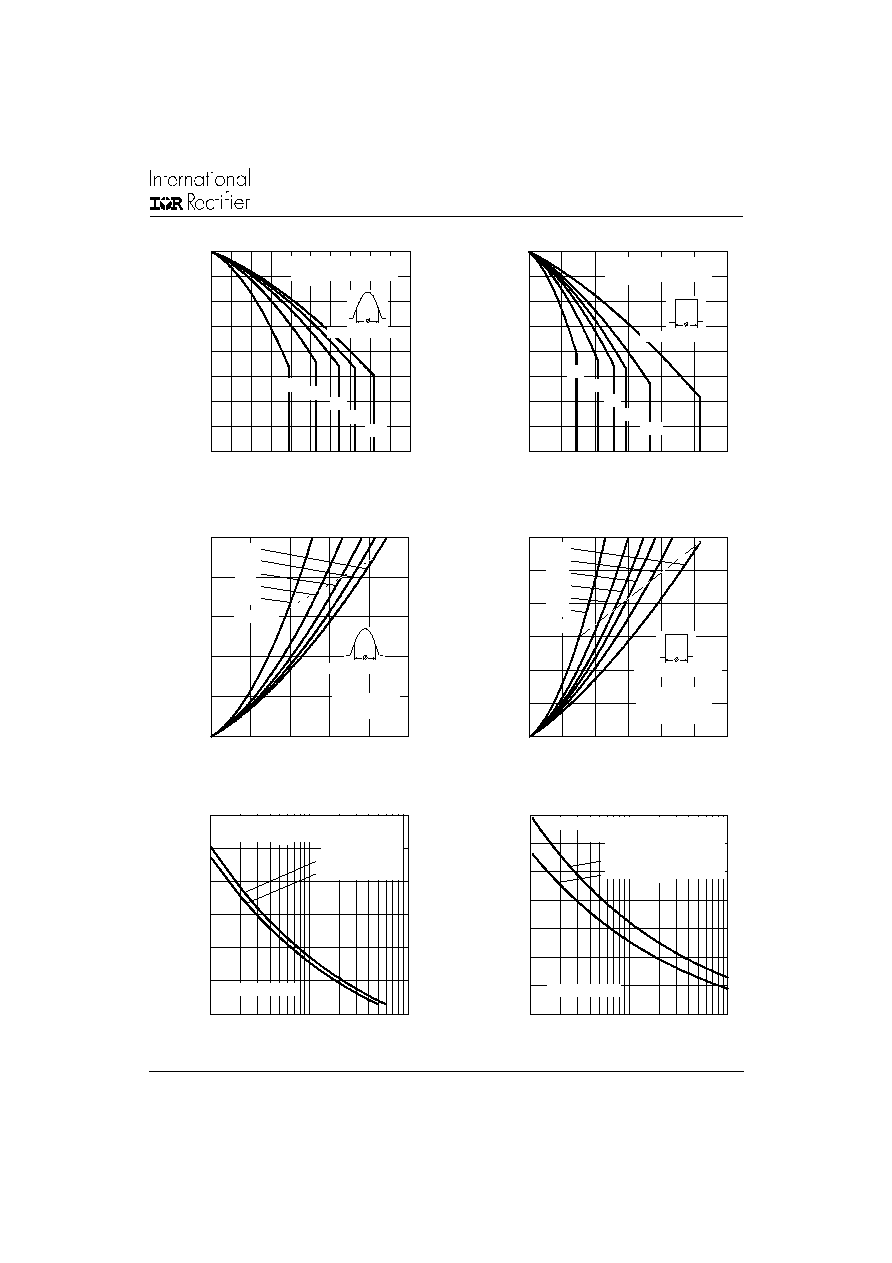
Fig.5 - Maximum Non-Repetitive Surge Current
Fig. 6 - Maximum Non-Repetitive Surge Current
Fig. 1 - Current Ratings Characteristics
Fig. 4 - On-State Power Loss Characteristics
Fig. 3 - On-State Power Loss Characteristics
Fig. 2 - Current Ratings Characteristics
70
80
90
1 0 0
1 1 0
1 2 0
1 3 0
1 4 0
1 5 0
0
4 0
80
12 0
1 6 0
2 00
3 0
6 0
9 0
1 2 0
1 8 0
M
a
x
i
m
u
m A
l
l
o
w
a
b
l
e
C
a
s
e
T
e
mp
e
r
a
t
u
r
e
(
C
)
C o nd uction A ng le
Ave rag e Forw a rd C urren t (A )
IRK.166.. Se rie s
R (D C ) = 0.20 K/W
thJ C
7 0
8 0
9 0
10 0
11 0
12 0
13 0
14 0
15 0
0
50
1 0 0
15 0
2 00
2 5 0
3 0 0
DC
30
60
90
120
180
M
a
x
i
m
u
m
Al
l
o
w
a
b
l
e C
a
s
e
T
e
m
p
er
a
t
u
r
e (
C
)
C o nd u ctio n P e rio d
A ve ra g e Forw ard C urre n t (A)
IRK.166.. Series
R (D C ) = 0.20 K/W
thJC
0
50
1 00
1 50
2 00
2 50
0
4 0
8 0
12 0
16 0
20 0
Averag e Forw ard C urre n t (A )
RM S Lim it
M
a
x
i
mu
m A
v
e
r
a
g
e
F
o
r
w
a
r
d
P
o
we
r
L
o
s
s
(
W
)
C o nd uc tio n Ang le
180
120
90
60
30
IRK.166.. Series
T = 15 0 C
J
0
50
10 0
15 0
20 0
25 0
30 0
0
5 0
1 00
15 0
20 0
25 0
3 00
D C
1 8 0
1 2 0
9 0
6 0
3 0
R M S Lim it
C o n d uc tio n P e r io d
A ve ra g e Forw ard C urre n t (A)
M
a
x
i
m
u
m
A
v
er
a
g
e F
o
r
w
a
r
d
P
o
w
e
r
L
o
s
s
(
W
)
IR K .1 6 6.. Se rie s
Pe r J u n ctio n
T = 15 0 C
J
1 0 00
1 5 00
2 0 00
2 5 00
3 0 00
3 5 00
4 0 00
1
10
1 0 0
P
e
ak
Ha
l
f
S
i
n
e
W
a
v
e
F
o
r
w
a
r
d C
u
r
r
e
n
t
(
A
)
N u m b e r O f Eq ua l A m p litud e Ha lf C yc le C urre nt Pu lses (N )
In itia l T = 1 5 0 C
@ 6 0 H z 0 .0 0 8 3 s
@ 5 0 H z 0 .0 1 0 0 s
At An y Ra ted Lo a d C o n d itio n A nd W ith
R a ted V A p p lie d F o llo w in g Surge .
R R M
J
IRK .1 6 6 .. Se rie s
50 0
1 0 00
1 5 00
2 0 00
2 5 00
3 0 00
3 5 00
4 0 00
0 .01
0 .1
1
P
e
ak
Ha
l
f
S
i
n
e
W
a
v
e
F
o
r
w
a
r
d
C
u
r
r
e
n
t
(
A
)
P u lse Train D ura tio n (s)
M axim um N on Rep etitive Surg e C urrent
Initial T = 150 C
N o V o ltag e Rea pp lied
Ra te d V Rea pp lied
Versus P ulse Train Dura tio n.
J
R R M
IRK.166.. Se ries