 | –≠–ª–µ–∫—Ç—Ä–æ–Ω–Ω—ã–π –∫–æ–º–ø–æ–Ω–µ–Ω—Ç: SD300N | –°–∫–∞—á–∞—Ç—å:  PDF PDF  ZIP ZIP |

SD300N/R
16 to 20
25 to 32
Features
Wide current range
High voltage ratings up to 3200V
High surge current capabilities
Stud cathode and stud anode version
Standard JEDEC types
Typical Applications
Converters
Power supplies
Machine tool controls
High power drives
Medium traction applications
Parameters
Units
I
F(AV)
380
380
A
@ T
C
100
70
∞C
I
F(RMS)
595
425
A
I
FSM
@
50Hz
6050
6050
A
@ 60Hz
6335
6335
A
I
2
t
@
50Hz
183
183
KA
2
s
@ 60Hz
167
167
KA
2
s
V
RRM
range
1600 to 2000
2500 to 3200
V
T
J
- 40 to 180
- 40 to 150
∞C
Major Ratings and Characteristics
case style
DO-205AB (DO-9)
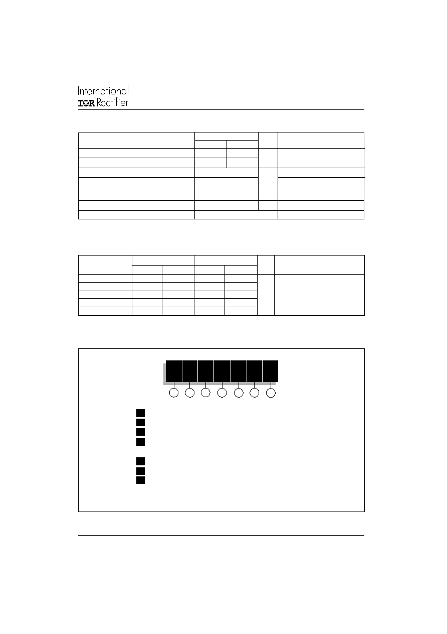
SD300N/R SERIES
STANDARD RECOVERY DIODES
Stud Version
1
380A
Bulletin I2081 rev.
C 03/03
www.irf.com

SD300N/R Series
2
www.irf.com
Bulletin I2081 rev.
C 03/03
Voltage
V
RRM
, maximum repetitive
V
RSM
, maximum non-
I
RRM
max.
Type number
Code
peak reverse voltage
repetitive peak rev. voltage
@ T
J
= T
J
max.
V
V
mA
16
1600
1700
20
2000
2100
25
2500
2600
28
2800
2900
32
3200
3300
ELECTRICAL SPECIFICATIONS
Voltage Ratings
SD300N/R
15
Forward Conduction
I
F(AV)
Max. average forward current
380
270
A
180∞ conduction, half sine wave
@ Case temperature
100
100
∞C
I
F(AV)
Max. average forward current
300
380
A
180∞ conduction, half sine wave
@ Case temperature
125
70
∞C
I
F(RMS)
Max. RMS forward current
595
425
A
DC @ T
C
= 88∞C (02 to 24), T
C
= 91∞C (25 to 32)
I
FSM
Max. peak, one-cycle forward,
6050
6050
t = 10ms
No voltage
non-repetitive surge current
6335
6335
t = 8.3ms
reapplied
5090
5090
t = 10ms
100% V
RRM
5330
5330
t = 8.3ms
reapplied
Sinusoidal half wave,
I
2
t
Maximum I
2
t for fusing
183
183
t = 10ms
No voltage
Initial T
J
= T
J
max.
167
167
t = 8.3ms
reapplied
129
129
t = 10ms
100% V
RRM
118
118
t = 8.3ms
reapplied
I
2
t
Maximum I
2
t for fusing
1830
1830
KA
2
s
t = 0.1 to 10ms, no voltage reapplied
V
F(TO)1
Low level value of threshold
voltage
V
F(TO)2
High level value of threshold
voltage
r
f
1
Low level value of forward
slope resistance
r
f
2
High level value of forward
slope resistance
V
FM
Max. forward voltage drop
1.83
1.83
V
I
pk
= 1180A, T
J
= T
J
max, t
p
= 10ms sinusoidal wave
Parameter
Units Conditions
0.66
0.66
(I >
x I
F(AV)
),T
J
= T
J
max.
0.75
0.75
(16.7% x
x I
F(AV)
< I <
x I
F(AV)
), T
J
= T
J
max.
m
1.05
1.05
(I >
x I
F(AV)
),T
J
= T
J
max.
0.95
0.95
(16.7% x
x I
F(AV)
< I <
x I
F(AV)
), T
J
= T
J
max.
V
KA
2
s
A
SD300N/R
16 to 20 25 to 32
SD300N/R Series
3
www.irf.com
Bulletin I2081 rev.
C 03/03
SD300N/R
16 to 20
25 to 32
T
J
Max. junction operating temperature range
-40 to 180
-40 to 150
T
stg
Max. storage temperature range
-55 to 200
-55 to 200
R
thJC
Max. thermal resistance, junction to case
0.11
DC operation
R
thCS
Max. thermal resistance, case
Mounting surface, smooth, flat and
to heatsink
greased
T
Max. allowed mounting torque ±10%
27
Nm
Not lubricated threads
wt
Approximate weight
250
g
Case style
DO-205AB (DO-9)
See Outline Table
∞C
K/W
0.04
Thermal and Mechanical Specifications
Parameter
Units
Conditions
16 to 20
25 to 32
16 to 20
25 to 32
180∞
0.019
0.019
0.013
0.013
120∞
0.023
0.023
0.023
0.023
90∞
0.028
0.028
0.030
0.030
K/W
T
J
= T
J
max.
60∞
0.042
0.042
0.044
0.044
30∞
0.073
0.073
0.074
0.074
Sinusoidal conduction Rectangular conduction
Conduction angle
Units
Conditions
Ordering Information Table
1
2
3
6
Device Code
SD 30
0
N
32
P
C
4
5
7
1
- Diode
2
- Essential part number
3
- 0 = Standard recovery
4
- N = Stud Normal Polarity (Cathode to Stud)
R = Stud Reverse Polarity (Anode to Stud)
5
- Voltage code: Code x 100 = V
RRM
(See Voltage Ratings table)
6
- P = Stud base DO-205AB (DO-9) 3/4" 16UNF-2A
7
- C = Ceramic Housing
NOTE: For metric Device M16 x 1.5 Contact Factory
R
thJC
Conduction
(The following table shows the increment of thermal resistence R
thJC
when devices operate at different conduction angles than DC)

SD300N/R Series
4
www.irf.com
Bulletin I2081 rev.
C 03/03
Outline Table
Conform to JEDEC DO-205AB (DO-9)
All dimensions in millimeters (inches)
MA
X
.
CERAMIC HOUSING
MAX.
MA
X
.
2
1
(
0
.8
2
)
MA
X
.
19 (0.75)
9.
5
(
0
.
3
7
)
M
I
N
.
DIA. 8.5 (0.33) NOM.
8
2
(
3
.2
3
)
M
I
N
.
DIA. 27.5 (1.08) MAX.
3
8
(
1
.5
0
)
1
6
(
0
.6
3
)
SW 32
21
0 (
8
.
27)
±
10 (
0
.
3
9
)
3/4"-16UNF-2A*
C.S. 35mm
4 (0.16) MAX.
3
9
(
1
.5
3
)
MA
X
.
2
(0.054 s.i.)
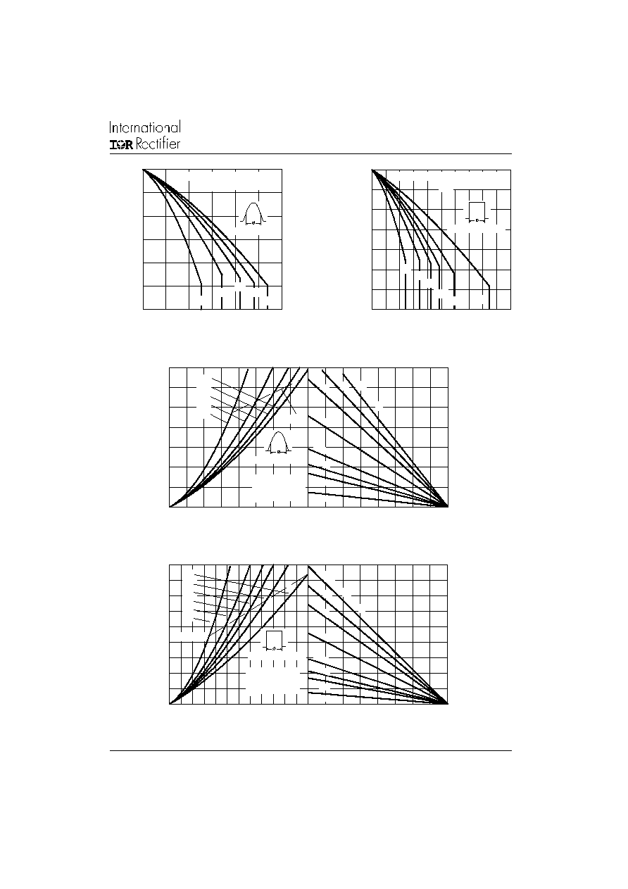
Fig. 1 - Current Ratings Characteristics
Fig. 2 - Current Ratings Characteristics
80
90
100
110
120
130
140
150
160
170
180
0
50 100 150 200 250 300 350 400
30∞
60∞
90∞
120∞
180∞
Average Forward Current (A)
Conduction Angle
M
a
x
i
mu
m
A
l
l
o
wa
b
l
e
Ca
s
e
T
e
m
p
e
r
at
u
r
e
(
∞
C
)
R (DC) = 0.11 K/ W
thJC
SD300N/ R Series (
1600V to 2000V)
80
90
100
110
120
130
140
150
160
170
180
0
100 200 300 400 500 600 700
30∞
60∞
90∞
180∞
DC
120∞
Average Forward Current (A)
Conduction Period
M
a
x
i
m
u
m A
l
l
o
w
a
b
l
e
Ca
s
e
T
e
mp
e
r
a
t
u
r
e
(∞
C)
R (DC) = 0.11 K/ W
thJC
SD300N/ R Series (
1600V to 2000V)
* FOR METRIC DEVICE: M16 X 1.5
CONTACT FACTORY
SD300N/R Series
5
www.irf.com
Bulletin I2081 rev.
C 03/03
Fig. 3 - Current Ratings Characteristics
Fig. 4 - Current Ratings Characteristics
Fig. 5 - Forward Power Loss Characteristics
80
90
100
110
120
130
140
150
0
100
200
300
400
500
30∞
60∞
90∞
180∞
DC
120∞
Average Forward Current (A)
Conduction Period
Ma
x
i
mu
m
A
l
l
o
w
a
b
l
e
C
a
s
e
T
e
m
p
er
a
t
u
r
e
(
∞
C
)
SD300N/ R Series (2500V to 3200V)
R (DC) = 0.11 K/ W
thJC
90
100
110
120
130
140
150
0
50
100
150
200
250
300
30∞
60∞
90∞
120∞
180∞
Average Forward Current (A)
Conduction Angle
M
a
x
i
m
u
m A
l
l
o
w
a
b
l
e C
a
s
e
T
e
mp
e
r
a
t
u
r
e (
∞
C
)
R (DC) = 0.11 K/ W
thJC
SD300N/ R Series (2500V to 3200V)
20
40
60
80 100 120 140 160 180
Maximum Allowable Ambient Temperature (∞C)
R
=
0.0
3 K
/W
- D
elt
a R
th
SA
0.0
6 K
/W
0.4 K
/ W
0.2 K
/ W
0.1
K/W
0.6 K/W
0.8 K/ W
2 K/W
0
100
200
300
400
500
600
700
0
50 100 150 200 250 300 350 400
180∞
120∞
90∞
60∞
30∞
RMS Limit
Conduc tion Angle
M
a
x
i
m
u
m A
v
er
a
g
e F
o
r
w
a
r
d
P
o
wer
L
o
s
s
(
W
)
Average Forward Current (A)
SD300N/ R Series
(
1600V to 2000V)
T = 180∞C
J
Fig. 6 - Forward Power Loss Characteristics
20
40
60
80 100 120 140 160 180
Maximum Allowable Ambient Temperature (∞C)
R
=
0.0
3 K
/W
- D
elta
R
th
SA
0.0
6 K
/ W
0.4 K/W
0.2 K
/W
0.1
K/W
0.6 K/W
0.8 K/W
2 K/ W
0
100
200
300
400
500
600
700
800
900
0
100
200
300
400
500
600
DC
180∞
120∞
90∞
60∞
30∞
RMS Limit
Conduction Period
M
a
x
i
m
u
m
A
v
e
r
a
g
e F
o
r
w
ar
d P
o
w
e
r
L
o
s
s
(
W
)
Average Forward Current (A)
SD300N/ R Series
(
1600V to 2000V)
T = 180∞C
J