 | ÐлекÑÑоннÑй компоненÑ: SD400CxxC | СкаÑаÑÑ:  PDF PDF  ZIP ZIP |
SD400_revD
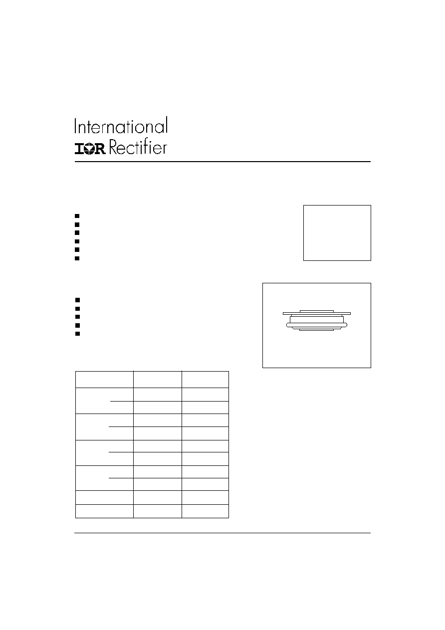
Features
Wide current range
High voltage ratings up to 2400V
High surge current capabilities
Diffused junction
Hockey Puk version
Case style DO-200AA
Typical Applications
Converters
Power supplies
Machine tool controls
High power drives
Medium traction applications
case style DO-200AA
Major Ratings and Characteristics
I
F(AV)
800
A
@ T
hs
55
°C
I
F(RMS)
1435
A
@ T
hs
25
°C
I
FSM
@
50Hz
8250
A
@ 60Hz
8640
A
I
2
t
@
50Hz
340
KA
2
s
@ 60Hz
311
KA
2
s
V
RRM
range
400 to 2400
V
T
J
- 40 to 190
°C
Parameters
SD400C..C
Units
SD400C..C SERIES
STANDARD RECOVERY DIODES
Hockey Puk Version
800A
1
Bulletin I2084 rev. D 11/01
www.irf.com
SD400C..C Series
2
Bulletin I2084 rev. D 11/01
www.irf.com
I
F(AV)
Max. average forward current
800 (425)
A
180° conduction, half sine wave
@ Heatsink temperature
55 (85)
°C
Double side (single side) cooled
I
F(RMS)
Max. RMS forward current
1435
A
@ 25°C heatsink temperature double side cooled
I
FSM
Max. peak, one-cycle forward,
8250
t = 10ms
No voltage
non-repetitive surge current
8640
t = 8.3ms
reapplied
6940
t = 10ms
50% V
RRM
7265
t = 8.3ms
reapplied
Sinusoidal halfwave,
I
2
t
Maximum I
2
t for fusing
340
t = 10ms
No voltage
Initial T
J
= T
J
max.
311
t = 8.3ms
reapplied
241
t = 10ms
50% V
RRM
220
t = 8.3ms
reapplied
I
2
t
Maximum I
2
t for fusing
3400
KA
2
s
t = 0.1 to 10ms, no voltage reapplied
V
F(TO)1
Low level value of threshold
voltage
V
F(TO)2
High level value of threshold
voltage
r
f
1
Low level value of forward
slope resistance
r
f
2
High level value of forward
slope resistance
V
FM
Max. forward voltage drop
1.86
V
I
pk
= 1930A, T
J
= T
J
max, t
p
= 10ms sinusoidal wave
A
KA
2
s
0.80
(16.7% x
x I
F(AV)
< I <
x I
F(AV)
), T
J
= T
J
max.
Parameter
SD400C..C
Units
Conditions
Forward Conduction
V
m
0.55
(16.7% x
x I
F(AV)
< I <
x I
F(AV)
), T
J
= T
J
max.
0.83
(I >
x I
F(AV)
),T
J
= T
J
max.
0.53
(I >
x I
F(AV)
),T
J
= T
J
max.
Voltage
V
RRM
, maximum repetitive
V
RSM
, maximum non-
I
RRM
max.
Type number
Code
peak reverse voltage
repetitive peak rev. voltage
@ T
J
= 150°C
V
V
mA
04
400
500
08
800
900
12
1200
1300
SD400C..C
16
1600
1700
15
20
2000
2100
25
2500
2600
28
2800
2900
32
3200
3300
ELECTRICAL SPECIFICATIONS
Voltage Ratings
SD400C..C Series
3
Bulletin I2084 rev. D 11/01
www.irf.com
R
thJ-hs
Conduction
(The following table shows the increment of thermal resistence R
thJ-hs
when devices operate at different conduction angles than DC)
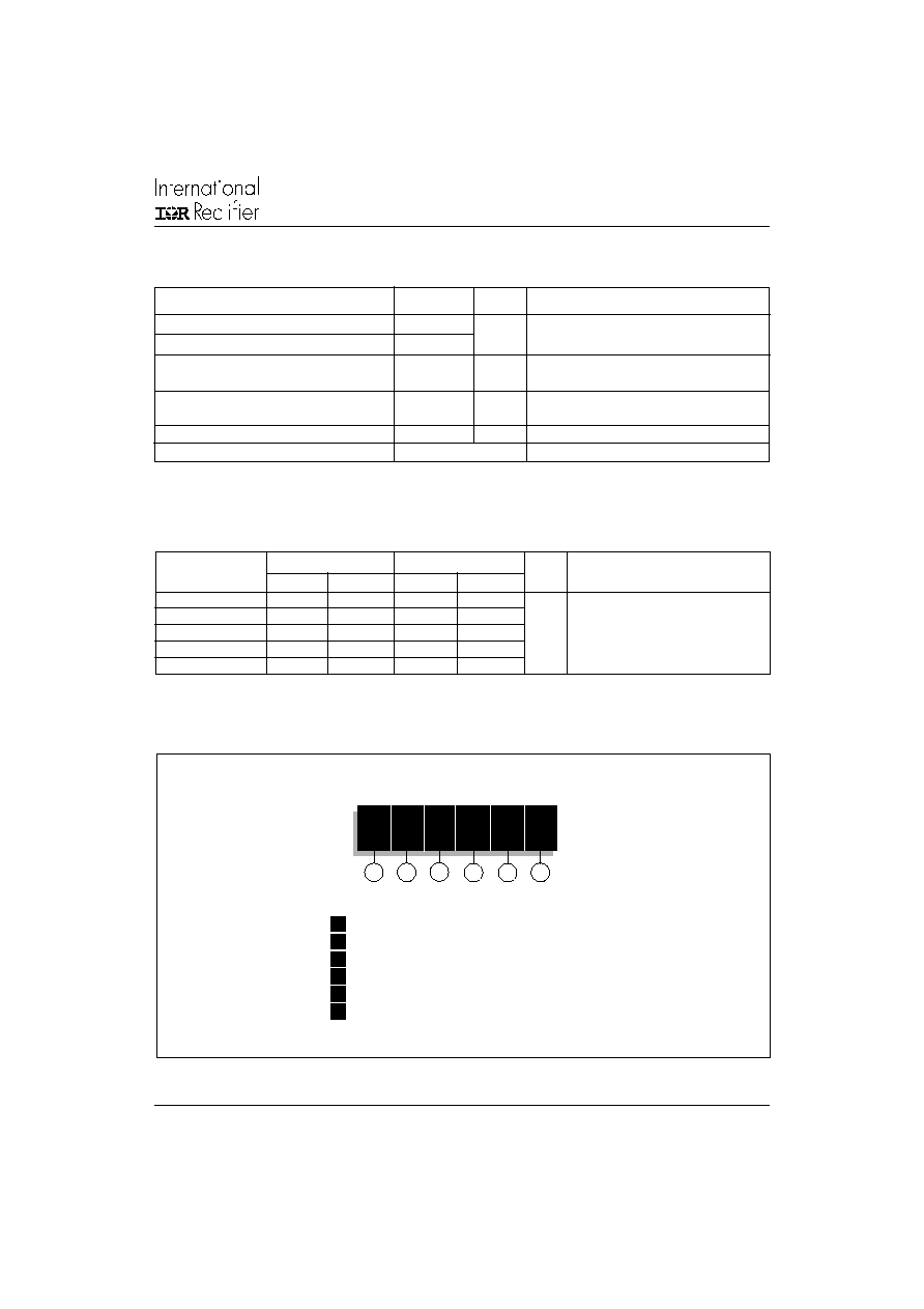
Ordering Information Table
1
-
Diode
2
-
Essential part number
3
-
0 = Standard recovery
4
-
C = Ceramic Puk
5
-
Voltage code: code x 100 = V
RRM
(see Voltage Ratings Table)
6
-
C = Puk Case DO-200AA
1
2
3
4
5
6
Device Code
SD 40
0
C
24
C
Sinusoidal conduction Rectangular conduction
Conduction angle
Units
Conditions
Single Side Double Side Single Side Double Side
180°
0.017
0.018
0.011
0.012
120°
0.020
0.020
0.020
0.020
90°
0.025
0.025
0.027
0.027
K/W
T
J
= T
J
max.
60°
0.037
0.036
0.038
0.038
30°
0.064
0.062
0.065
0.062
T
J
Max. junction operating temperature range
-40 to 190
T
stg
Max. storage temperature range
-55 to 200
R
thJ-hs
Max. thermal resistance, junction
0.163
DC operation single side cooled
to heatsink
0.073
DC operation double side cooled
F
Mounting force, ± 10%
4900
N
(500)
(Kg)
wt
Approximate weight
70
g
Case style
DO-200AA
See Outline Table
Parameter
SD400C..C
Units
Conditions
Thermal and Mechanical Specifications
°C
K/W
SD400C..C Series
4
Bulletin I2084 rev. D 11/01
www.irf.com
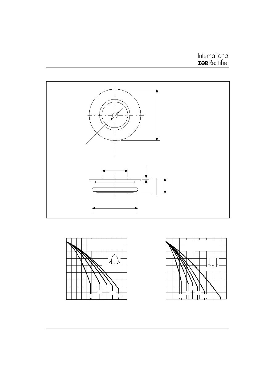
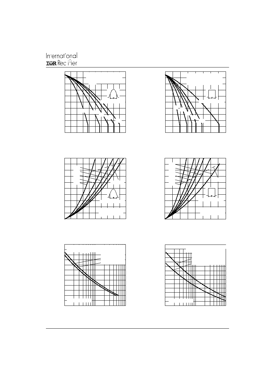
Fig. 1 - Current Ratings Characteristics
Fig. 2 - Current Ratings Characteristics
Outline Table
Case Style DO-200AA
All dimensions in millimeters (inches)
0.3 (0.01) MIN.
BOTH ENDS
4
2
(
1
.6
5
)
D
I
A
.
M
A
X
.
38 (1.50) DIA. MAX.
TWO PLACES
3.5(0.14) ± 0.1(0.004) DIA. NOM.x
1.8 (0.07) DEEP MIN. BOTH ENDS
19(0.75) DIA. MAX.
1
4
.4
(
0
.5
7
)
13.
7
(
0
.
5
4)
2 0
4 0
6 0
8 0
1 00
1 20
1 40
1 60
1 80
2 00
0
1 0 0
2 0 0
30 0
4 00
50 0
6 00
30
60
90
120
180
A ve ra g e Forw a rd C urren t (A)
M
a
x
i
m
u
m
A
l
l
o
w
a
b
l
e
He
at
s
i
n
k
T
e
m
p
e
r
a
t
u
r
e
(
C
)
C o nd uc tio n A ngle
SD 400C ..C Series
(Sin g le Side C oole d)
R (D C ) = 0.163 K/W
thJ-hs
20
40
60
80
1 00
1 20
1 40
1 60
1 80
2 00
0
1 0 0 2 0 0 3 0 0 4 0 0 50 0 6 0 0 70 0 8 00 90 0
30
60
90
180
D C
120
A ve rag e Forw ard C urre n t (A)
Ma
x
i
mu
m
A
l
l
o
w
a
b
l
e
H
e
a
t
s
i
n
k
T
e
mp
e
r
a
t
u
r
e
(
C
)
C o nd uc tion P e rio d
SD 400C ..C Se rie s
(Sing le Side C ooled)
R (D C ) = 0.163 K/W
th J-hs
Quote between upper and lower
pole pieces has to be considered
after application of Mounting Force
(see Thermal and Mechanical
Specification)
SD400C..C Series
5
Bulletin I2084 rev. D 11/01
www.irf.com
Fig. 3 - Current Ratings Characteristics
Fig. 4 - Current Ratings Characteristics
Fig. 5 - Forward Power Loss Characteristics
Fig. 6 - Forward Power Loss Characteristics
Fig. 8 - Maximum Non-Repetitive Surge Current
Single and Double Side Cooled
Fig. 7 - Maximum Non-Repetitive Surge Current
Single and Double Side Cooled
0
20
40
60
80
10 0
12 0
14 0
16 0
18 0
20 0
0
40 0
8 00
1 20 0
1 6 00
30
60
90
180
D C
120
A ve ra g e Forw a rd C urre n t (A )
M
a
x
i
m
u
m
A
l
l
o
w
a
b
l
e H
e
a
t
s
i
nk
T
e
m
p
er
a
t
u
r
e (
C
)
C o nd uc tion P e rio d
SD 400C ..C Series
(D ouble Side C ooled)
R (D C ) = 0.073 K/W
th J-hs
0
20
40
60
80
1 0 0
1 2 0
1 4 0
1 6 0
1 8 0
2 0 0
0
2 0 0
4 00
60 0
8 0 0
1 0 0 0
30
60
90
120
180
A ve ra g e Forw a rd C urren t (A )
Ma
x
i
mu
m A
l
l
o
wa
b
l
e
H
e
a
t
s
i
n
k
T
e
m
p
e
r
a
t
u
r
e
(
C
)
C o nd u ction A ng le
SD 400C ..C Series
(D oub le Sid e C ooled )
R (D C ) = 0.073 K/W
thJ-h s
0
2 0 0
4 0 0
6 0 0
8 0 0
1 0 0 0
1 2 0 0
1 4 0 0
1 6 0 0
1 8 0 0
2 0 0 0
0
2 0 0
4 00
6 0 0
8 0 0
1 0 0 0
180
120
90
60
30
RM S Lim it
C o nd uc tio n A n g le
Ma
x
i
mu
m A
v
e
r
a
g
e
F
o
r
w
a
r
d
P
o
w
e
r
L
o
s
s
(
W
)
A ve ra g e Forw a rd C urre n t (A )
SD 400C ..C Se rie s
T = 190 C
J
2 00 0
3 00 0
4 00 0
5 00 0
6 00 0
7 00 0
8 00 0
1
10
10 0
Num b e r O f E q ua l A m p litud e H a lf C y cle C urre nt P u lses (N )
P
e
ak
Ha
l
f
S
i
n
e
W
a
v
e
F
o
r
w
a
r
d C
u
r
r
e
n
t
(
A
)
SD 400C ..C Se rie s
In itia l T = 190 C
@ 60 H z 0.0083 s
@ 50 H z 0.0100 s
J
A t An y Rate d Loa d C on d itio n A nd W ith
Ra ted V Ap p lied Follow in g Su rg e .
R R M
2 000
3 000
4 000
5 000
6 000
7 000
8 000
9 000
0 .01
0.1
1
Pu lse Train D uration (s)
P
e
a
k
Ha
l
f
S
i
n
e
W
a
v
e
F
o
r
w
ar
d
C
u
r
r
e
n
t
(
A
)
V e rsus Pulse Train D ura tion .
M axim um Non Repe titive Surge C urren t
SD 400C ..C S erie s
In itia l T = 190 C
No V olta g e Re a pp lie d
Ra te d V Re a pp lie d
RRM
J
0
50 0
1 0 0 0
1 5 0 0
2 0 0 0
2 5 0 0
0
4 00
80 0
1 2 00
1 6 0 0
D C
180
120
90
60
30
RM S Lim it
C o nd uc tio n P erio d
M
a
x
i
mu
m A
v
e
r
a
g
e
F
o
r
w
a
r
d
P
o
w
e
r
L
o
s
s
(
W
)
A ve ra g e Forw ard C urren t (A )
SD 400C ..C S erie s
T = 190 C
J