 | –≠–ª–µ–∫—Ç—Ä–æ–Ω–Ω—ã–π –∫–æ–º–ø–æ–Ω–µ–Ω—Ç: IXBOD1 | –°–∫–∞—á–∞—Ç—å:  PDF PDF  ZIP ZIP |
Document Outline
- Main Menu
- Search by Product Family
- Breakover Diodes

H - 1
© 2000 IXYS All rights reserved
Breakover Diodes
Applications
l
Transient voltage protection
l
High-voltage switches
l
Crowbar
l
Lasers
l
Pulse generators
i
V
V
H
V
BO
I
H
I
BO
Application Note H - 6
Remark: For special selection of more than 2 pieces IXBOD 1-... for every
break down voltage of V
BO
> 2000 V please contact us.

H - 2
© 2000 IXYS All rights reserved
Symbol
Conditions Ratings
I
D
T
VJ
= 125∞C;
V = 0,8x V
BO
20
µA
V
BO
V
BO
(T
VJ
) = V
BO, 25∞C
[1 +
K
T
(T
VJ
- 25∞C)]
I
RMS
f = 50 HZ;
T
amb
= 50∞C
1.4
A
connection pins soldered to printed circuit
(conductor 0,035x2mm)
I
AVM
0.9
A
I
SM
t
p
= 0.1 ms;
T
amb
= 50∞C non repetitive
200
A
I≤t
t
p
= 0.1 ms;
T
amb
= 50∞C
2
A
2
s
T
amb
-40...+125
∞C
T
stg
-40...+125
∞C
T
VJm
125
∞C
K
T
Temperatur coefficient of V
BO
2∑10
-3
K
-1
K
P
coefficient for energy per pulse E
P
(material constant)
700
K/Ws
R
thJA
- natural convection
60
K/W
- with air speed 2 m/s
45
K/W
Weight
1
g
Symbol
Conditions
Characteristic Values
I
BO
T
VJ
=
25∞C
15
mA
I
H
T
VJ
=
25∞C
30
mA
V
H
T
VJ
=
25∞C
4 - 8
V
(dv/dt)
C
T
VJ
=
50∞C;
V
D
= 0.67∑(V
BO
+ 100V)
>
1000
V/µs
(di/dt)
C
T
VJ
= 125∞C;
V
D
= V
BO
; I
T
= 80A; f = 50 Hz
200
A/µs
t
q(typ)
T
VJ
= 125∞C
V
D
= 0.67∑V
BO
; V
R
= 0V
150
µs
dV/dt
(lin.)
= 200V/µs; I
T
= 80A; di/dt = -10A/µs
V
T
T
VJ
=125∞C; I
T
= 5A
1.7
V
V
(TO)
For power-loss calculations only
1.1
V
r
T
T
VJ
= 125∞C
0.12
V
BO
Standard
V
Types
600 ±50
IXBOD 1 -06
700 ±50
IXBOD 1 -07
800 ±50
IXBOD 1 -08
900 ±50
IXBOD 1 -09
1000 ±50
IXBOD 1 -10
V
BO
= 600-1000V
I
AVM
= 0.9 A
IXBOD 1 -06...10
Dimensions in mm (1 mm = 0.0394")
A
K
K
A
Single Breakover Diode
030
IXYS reserve at these the right to change limits, test conditions and dimensions; Data according to IEC 60747
H - 3
© 2000 IXYS All rights reserved
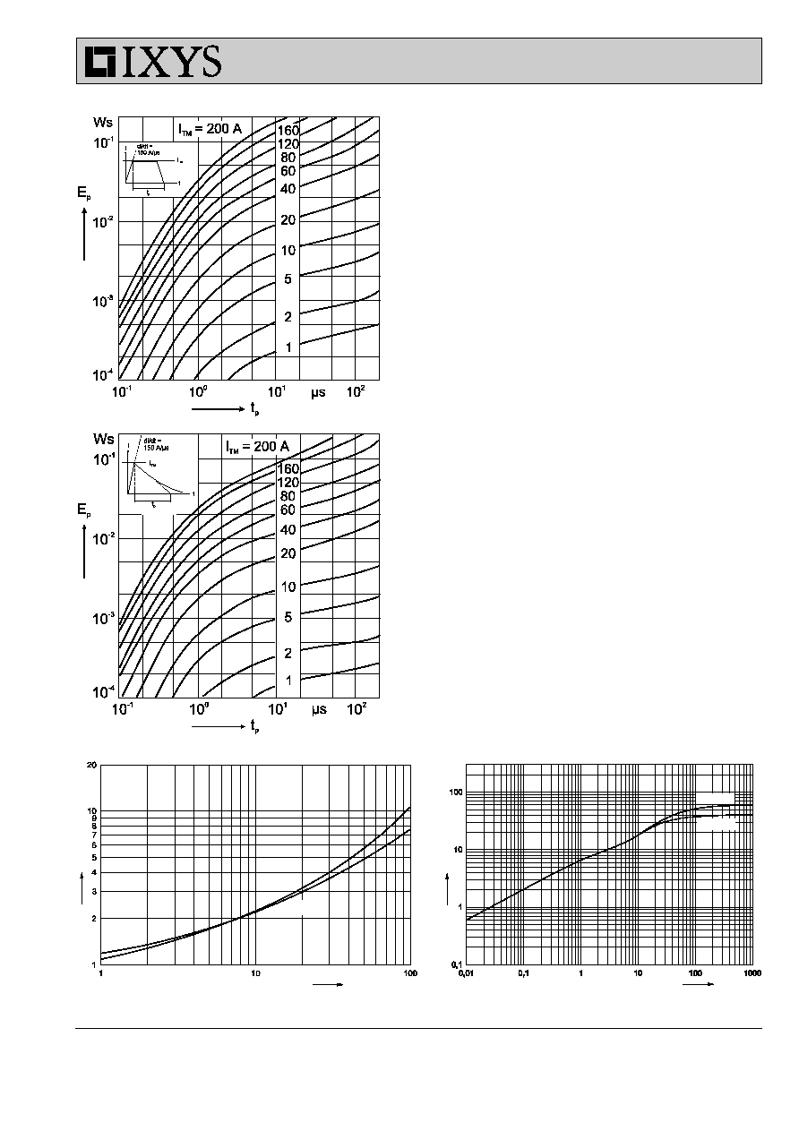
IXBOD 1 -06...10
Fig. 4 Transient thermal resistance.
Fig. 3 On-state voltage
V
a
= 0 m/s
V
a
= 2 m/s
Fig. 2 Energy per pulse for exponentially decaying
current pulse (see waveforms definition).
Fig. 1 Energy per pulse for trapezoidal current wafeforms
(see waveform definition).
t
[s]
T
VJ
= 125∞C
T
VJ
= 25∞C
i
T
[A]
[V]
V
T
[K/W]
Z
thJA

H - 4
© 2000 IXYS All rights reserved
Symbol
Test Conditions
2 BODs
3 BODs
4 BODs
D-Version
I
D
T
VJ
=
125∞C;V = 0,8x V
BO
100
100
100
100
µA
V
BO
V
BO
(T
VJ
) = V
BO, 25∞C
[1 +
K
T
(T
VJ
- 25∞C)]
I
RMS
f = 50 HZ;
T
amb
= 50∞C
2.0
1.4
1.1
0.3
A
connection pins soldered to printed circuit
(conductor 0,035x2mm)
I
AVM
1.25
0.9
0.7
0.2
A
I
SM
t
p
= 0.1 ms;
T
amb
= 50∞C non repetitive
200
200
200
50
A
I≤t
t
p
= 0.1 ms;
T
amb
= 50∞C
2
2
2
0.125
A
2
s
V
T
T
VJ
=125∞C; I
T
= 5A
3.4
5.1
6.8
27
V
V
(TO)
For power-loss calculations only
2.2
3.3
4.4
17.5
V
r
T
T
VJ
=125∞C
0.24
0.36
0.48
3
T
amb
-40...+125
-40...+125
-40...+125
-40...+125
∞C
T
stg
-40...+125
-40...+125
-40...+125
-40...+125
∞C
T
VJm
125
125
125
125
∞C
K
T
Temperatur coefficient of V
BO
2∑10
-3
2∑10
-3
2∑10
-3
2∑10
-3
K
-1
K
P
coefficient for energy per pulse E
P
(material constant)
700
700
700
700
K/Ws
R
thJA
- natural convection
20
20
20
20
K/W
- with air speed 2 m/s
16
16
16
16
K/W
Weight
typical
14
14
14
14
g
Breakover Diode Modules
V
BO
Standard
BOD -
V
Types
Elements
1200 ±50
IXBOD 1 -12R(D)
2
1300 ±50
IXBOD 1 -13R(D)
2
1400 ±50
IXBOD 1 -14R(D)
2
1500 ±50
IXBOD 1 -15R(D)
2
1600 ±50
IXBOD 1 -16R(D)
2
1700 ±50
IXBOD 1 -17R(D)
2
1800 ±50
IXBOD 1 -18R(D)
2
1900 ±50
IXBOD 1 -19R(D)
2
V
BO
Standard
BOD -
V
Types
Elements
2000 ±50
IXBOD 1 -20R(D)
3
2100 ±50
IXBOD 1 -21R(D)
3
2200 ±50
IXBOD 1 -22R(D)
3
2300 ±50
IXBOD 1 -23R(D)
3
2400 ±50
IXBOD 1 -24R(D)
3
2500 ±50
IXBOD 1 -25R(D)
3
2600 ±100 IXBOD 1 -26R(D)
3
2800 ±100 IXBOD 1 -28R(D)
3
3000 ±100 IXBOD 1 -30R(D)
3
3200 ±100 IXBOD 1 -32R(D)
3
V
BO
Standard
BOD -
V
Types
Elements
3400 ±100 IXBOD 1 -34R
4
3600 ±100 IXBOD 1 -36R
4
3800 ±100 IXBOD 1 -38R
4
4000 ±100 IXBOD 1 -40R
4
4200 ±100 IXBOD 1 -42R
4
Symbol
Test Conditions
Characteristic Values both Versions R & RD
2 BODs
3 BODs
4 BODs
I
BO
T
VJ
=
25∞C
15
15
15
mA
I
H
T
VJ
=
25∞C
30
30
30
mA
V
H
T
VJ
=
25∞C
4 - 8
4 - 8
4 - 8
V
(dv/dt)
C
T
VJ
=
50∞C;
V
D
= 0.67∑(V
BO
+ 100V)
- V
BO
bis 1500V
> 1000
-
-
V/µs
- V
BO
1600 - 2000V
> 1500
-
-
V/µs
- V
BO
2100 - 2500V
-
> 2000
-
V/µs
- V
BO
2600 - 3000V
-
> 2500
-
V/µs
- V
BO
3200 - 3400V
-
-
> 3000
V/µs
- V
BO
3600 - 4200V
-
-
> 3500
V/µs
(di/dt)
C
T
VJ
= 125∞C;
V
D
= V
BO
; I
T
= 80A; f = 50 Hz
200
200
200
A/µs
t
q(typ)
T
VJ
= 125∞C
V
D
= 0.67∑V
BO
; V
R
= 0V
150
150
150
µs
dv/dt
(lin.)
= 200V/µs; I
T
= 80A; di/dt = -10A/µs
IXBOD 1 -12R...42R(D)
2-3 BODs
Version: R
Version: RD
IXYS reserve at these the right to change limits, test conditions and dimensions; Data according to IEC 60747
032
H - 5
© 2000 IXYS All rights reserved
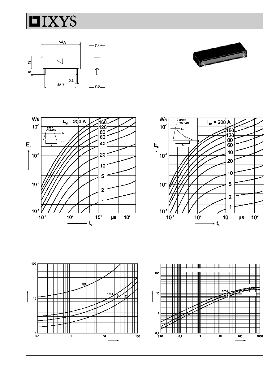
IXBOD 1 -12R...42R(D)
Fig. 8 Transient thermal resistance.
K
A
Dimensions in mm (1 mm = 0.0394")
Fig. 5 Energy per pulse for single BOD element
for trapezoidal wave current. E
P
must be multiplied
by number of elements for total energy.
Fig. 6 Energy per pulse for single BOD element
for exponentially decaying current pulse. E
P
must
be multiplied by number of elements for total
energy.
K
A
V
a
= 2 m/s
n = number of BOD-Elements in series
V
a
= 0 m/s
[K/W]
Z
thJA
t
[s]
Fig. 7 On-state voltage at T
VJ
= 125∞C.
[V]
V
T
i
T
[A]