
1 - 4
© 2005 IXYS All rights reserved
IXEH 25N120
IXEH 25N120D1
0549
Features
∑ NPT
3
IGBT
- positive temperature coefficient of
saturation voltage for easy paralleling
- fast switching
- short tail current for optimized
performance in resonant circuits
∑ optional HiPerFRED
TM
diode
- fast reverse recovery
- low operating forward voltage
- low leakage current
∑ TO-247 package
- industry standard outline
- epoxy meets UL 94V-0
Applications
∑ AC drives
∑ DC drives and choppers
∑ Uninteruptible power supplies (UPS)
∑ switched-mode and resonant-mode
power supplies
∑ inductive heating, cookers
IGBT
Symbol
Conditions
Maximum Ratings
V
CES
T
VJ
= 25∞C to 150∞C
1200
V
V
GES
± 20
V
I
C25
T
C
= 25∞C
36
A
I
C90
T
C
= 90∞C
24
A
I
CM
V
GE
=
±15 V; R
G
= 68
; T
VJ
= 125∞C
60
A
V
CEK
RBSOA, Clamped inductive load; L = 100 µH
V
CES
t
SC
V
CE
= 900V; V
GE
=
±15 V; R
G
= 68
; T
VJ
= 125∞C
10
µs
(SCSOA)
non-repetitive
P
tot
T
C
= 25∞C
200
W
I
C25
= 36 A
V
CES
= 1200 V
V
CE(sat) typ
= 2.6 V
NPT
3
IGBT
TO-247 AD
G
E
C
C (TAB)
IXEH 25N120
C
E
G
Symbol
Conditions
Characteristic Values
(T
VJ
= 25
∞C, unless otherwise specified)
min.
typ.
max.
V
CE(sat)
I
C
= 25 A; V
GE
= 15 V; T
VJ
= 25∞C
2.6
3.2
V
T
VJ
= 125∞C
3.2
V
V
GE(th)
I
C
= 0.6 mA; V
GE
= V
CE
4.5
6.5
V
I
CES
V
CE
= V
CES
;
V
GE
= 0 V; T
VJ
= 25∞C
0.2
mA
T
VJ
= 125∞C
0.2
mA
I
GES
V
CE
= 0 V; V
GE
=
± 20 V
200
nA
t
d(on)
205
ns
t
r
105
ns
t
d(off)
320
ns
t
f
175
ns
E
on
4.1
mJ
E
off
1.5
mJ
C
ies
V
CE
= 25 V; V
GE
= 0 V; f = 1 MHz
1.2
nF
Q
Gon
V
CE
= 600 V; V
GE
= 15 V; I
C
= 20 A
100
nC
R
thJC
0.63 K/W
Inductive load, T
VJ
= 125∞C
V
CE
= 600 V; I
C
= 20 A
V
GE
= ±15 V; R
G
= 68
IXEH 25N120D1
C
E
G
2 - 4
© 2005 IXYS All rights reserved
IXEH 25N120
IXEH 25N120D1
0549
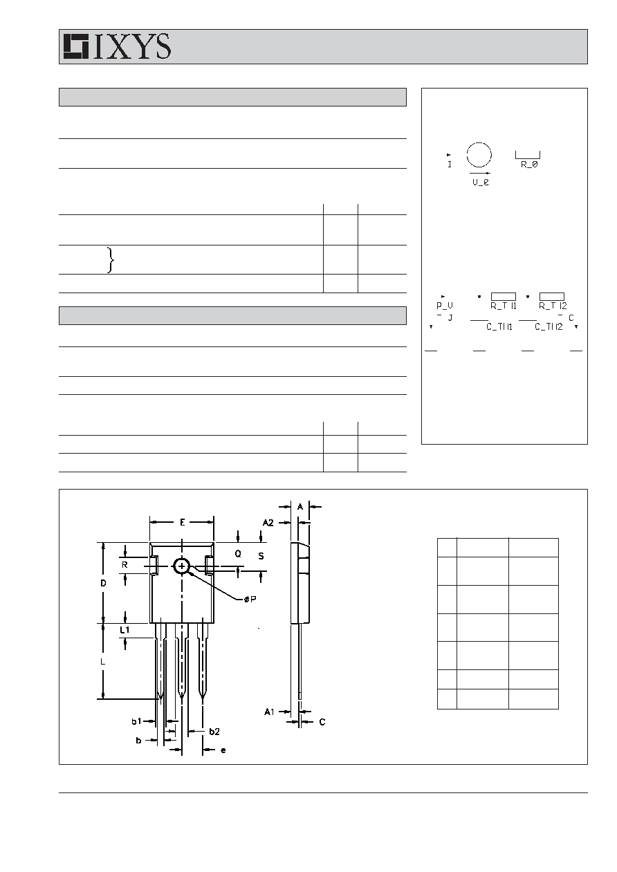
TO-247 AD Outline
Component
Symbol
Conditions
Maximum Ratings
T
VJ
-55...+150
∞C
T
stg
-55...+150
∞C
M
d
mounting torque
0.8...1.2
Nm
Symbol
Conditions
Characteristic Values
min.
typ.
max.
R
thCH
with heatsink compound
0.25
K/W
Weight
6
g
Diode [D1 version only
]
Symbol
Conditions
Maximum Ratings
I
F25
T
C
= 25∞C
31
A
I
F90
T
C
= 90∞C
19
A
Symbol
Conditions
Characteristic Values
min.
typ.
max.
V
F
I
F
= 25 A; T
VJ
= 25∞C
2.7
3.2
V
T
VJ
= 125∞C
2.1
V
I
RM
I
F
= 15 A; di
F
/dt = -400 A/µs; T
VJ
= 125∞C
16
A
t
rr
V
R
= 600 V; V
GE
= 0 V
130
ns
R
thJC
1.6 K/W
Equivalent Circuits for Simulation
Conduction
IGBT (typ. at V
GE
= 15 V; T
J
= 125∞C)
V
0
= 1.09 V; R
0
= 85 m
Free Wheeling Diode (typ. at T
J
= 125∞C)
V
0
= 1.3 V; R
0
= 32 m
Thermal Response
IGBT (typ.)
C
th1
= 0.004 J/K; R
th1
= 0.335 K/W
C
th2
= 0.133 J/K; R
th2
= 0.295 K/W
Free Wheeling Diode (typ.)
C
th1
= 0.004 J/K; R
th1
= 1.076 K/W
C
th2
= 0.078 J/K; R
th2
= 0.524 K/W
Dim.
Millimeter
Inches
Min.
Max.
Min.
Max.
A
4.7
5.3
.185
.209
A
1
2.2
2.54
.087
.102
A
2
2.2
2.6
.059
.098
b
1.0
1.4
.040
.055
b
1
1.65
2.13
.065
.084
b
2
2.87
3.12
.113
.123
C
.4
.8
.016
.031
D
20.80
21.46
.819
.845
E
15.75
16.26
.610
.640
e
5.20
5.72
0.205 0.225
L
19.81
20.32
.780
.800
L1
4.50
.177
P
3.55
3.65
.140
.144
Q
5.89
6.40
0.232 0.252
R
4.32
5.49
.170
.216
S
6.15 BSC
242 BSC
3 - 4
© 2005 IXYS All rights reserved
IXEH 25N120
IXEH 25N120D1
0549
0
200
400
600
800
1000
0
10
20
30
40
0
50
100
150
200
0
1
2
3
4
5
6
0
20
40
60
80
0
20
40
60
80
100
0
3
6
9
12
15
0
1
2
3
4
5
6
0
10
20
30
40
50
60
V
CE
V
I
C
V
CE
A
I
C
V
nC
Q
G
-di/dt
V
V
GE
I
RM
t
rr
A/
µs
FII30-12E
I
RM
t
rr
9 V
11 V
A
11 V
0
5
10
15
20
0
20
40
60
80
V
V
GE
A
I
C
0
1
2
3
4
0
10
20
30
40
50
V
V
F
I
F
A
ns
9 V
13 V
13 V
15 V
T
VJ
= 25∞C
T
VJ
= 125∞C
V
CE
= 20 V
T
VJ
= 125∞C
T
VJ
= 25∞C
T
VJ
= 125∞C
V
R
= 600 V
I
F
= 15 A
T
VJ
= 25∞C
V
GE
= 17 V
A
V
GE
= 17 V
T
VJ
= 125∞C
V
CE
= 600 V
I
C
= 20 A
15 V
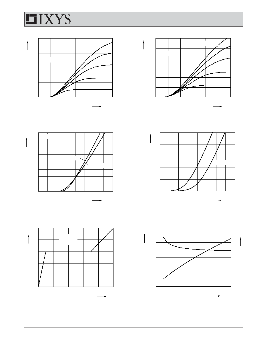
Fig. 1
Typ. output characteristics
Fig. 2
Typ. output characteristics
Fig. 3
Typ. transfer characteristics
Fig. 4
Typ. forward characteristics of
free wheeling diode
Fig. 5
Typ. turn on gate charge
Fig. 6
Typ. turn off characteristics of
free wheeling diode
4 - 4
© 2005 IXYS All rights reserved
IXEH 25N120
IXEH 25N120D1
0549
0
10
20
30
40
0
4
8
12
16
20
0
50
100
150
200
250
0
10
20
30
40
0.0
0.5
1.0
1.5
2.0
2.5
3.0
3.5
4.0
0
50
100
150
200
250
300
350
400
1
10
100
1000
10000
0.1
1
10
0
50
100
150
200
250
0.0
0.5
1.0
1.5
2.0
2.5
0
250
500
750
1000
1250
0
50
100
150
200
250
0
2
4
6
8
10
0
200
400
600
800
1000 1200
0
20
40
60
80
E
off
t
d(off)
t
f
E
on
t
r
E
off
t
d(off)
t
f
I
C
A
I
C
A
E
off
E
on
t
t
R
G
R
G
V
CE
t
ms
mJ
E
on
mJ
E
off
ns
t
I
CM
K/W
Z
thJC
V
A
mJ
ns
t
d(on)
V
CE
= 600 V
V
GE
= ±15 V
I
C
= 20 A
T
VJ
= 125∞C
V
CE
= 600 V
V
GE
= ±15 V
I
C
= 20 A
T
VJ
= 125∞C
V
CE
= 600 V
V
GE
= ±15 V
R
G
= 68
T
VJ
= 125∞C
V
CE
= 600 V
V
GE
= ±15 V
R
G
= 68
T
VJ
= 125∞C
R
G
= 68
T
VJ
= 125∞C
mJ
ns
single pulse
IGBT
diode
IXEH 25N120
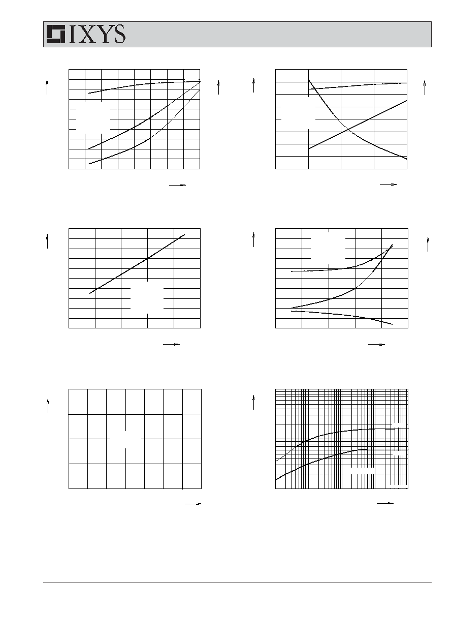
Fig. 7 Typ. turn on energy and switching
Fig. 8
Typ. turn off energy and switching
times versus collector current
times versus collector current
Fig. 9 Typ. turn on energy vs gate resistor
Fig.10 Typ. turn off energy and switching
times versus gate resistor
Fig. 11 Reverse biased safe operating area
Fig. 12 Typ. transient thermal impedance
RBSOA