© 2004 IXYS All rights reserved
V
CES
= 1700
V
I
C25
= 26
A
V
CE(sat)
= 5.2
V
t
fi(typ)
= 50 ns
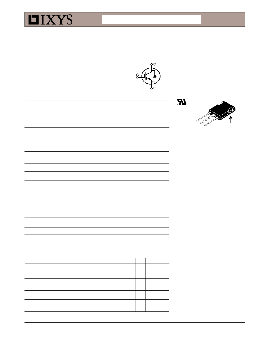
IXGR 32N170AH1
G = Gate,
C = Collector,
E = Emitter
Features
Electrically Isolated tab
High current handling capability
MOS Gate turn-on
- drive simplicity
Rugged NPT structure
Molding epoxies meet UL
94
V-0
flammability classification
Applications
Capacitor discharge & pulser circuits
AC motor speed control
DC servo and robot drives
DC choppers
Uninterruptible power supplies (UPS)
Switched-mode and resonant-mode
power supplies
DS99233(11/04)
Symbol
Test Conditions
Characteristic Values
(T
J
= 25
°C unless otherwise specified)
min.
typ.
max.
BV
CES
I
C
= 1mA, V
GE
= 0 V
1700
V
V
GE(th)
I
C
= 250
µA, V
CE
= V
GE
3.0
5.0
V
I
CES
V
CE
= 0.8 · V
CES
500
µA
V
GE
= 0 V
Note 1
T
J
= 125
°C
8
mA
I
GES
V
CE
= 0 V, V
GE
=
±20 V
±100
nA
V
CE(sat)
I
C
= I
C90
, V
GE
= 15 V
4.2
5.2
V
T
J
= 125
°C
4.8
V
Symbol
Test Conditions
Maximum Ratings
V
CES
T
J
= 25
°C to 150°C
1700
V
V
CGR
T
J
= 25
°C to 150°C; R
GE
= 1 M
1700
V
V
GES
Continuous
±20
V
V
GEM
Transient
±30
V
I
C25
T
C
= 25
°C
26
A
I
C90
T
C
= 90
°C
17
A
I
F90
14
A
I
CM
T
C
= 25
°C, 1 ms
200
A
SSOA
V
GE
= 15 V, T
VJ
= 125
°C, R
G
= 5
I
CM
= 70
A
(RBSOA)
Clamped inductive load
@ 0.8 V
CES
t
SC
T
J
= 125
°C, V
CE
= 1200 V; V
GE
= 15 V, R
G
= 10
10
µs
P
C
T
C
= 25
°C
200
W
T
J
-55 ... +150
°C
T
JM
150
°C
T
stg
-55 ... +150
°C
F
C
Mounting force with clamp
22...130/5...30
N/lb
V
ISOL
50/60 Hz, 1 minute
2500
~V
Maximum lead temperature for soldering
300
°C
1.6 mm (0.062 in.) from case for 10 s
Weight
5
g
High Voltage
IGBT with Diode
Advance Technical Information
Electrically Isolated Tab
ISOLATED TAB
E
G
C
ISOPLUS247 (IXGR)
E153432
IXYS reserves the right to change limits, test conditions, and dimensions.
IXYS MOSFETs and IGBTs are covered by
4,835,592
4,931,844
5,049,961
5,237,481
6,162,665
6,404,065 B1
6,683,344
6,727,585
one or moreof the following U.S. patents:
4,850,072
5,017,508
5,063,307
5,381,025
6,259,123 B1
6,534,343
6,710,405B2
6,759,692
4,881,106
5,034,796
5,187,117
5,486,715
6,306,728 B1
6,583,505
6,710,463
Symbol
Test Conditions
Characteristic Values
(T
J
= 25
°C unless otherwise specified)
min.
typ.
max.
g
fs
I
C
= I
C25
; V
CE
= 10 V
25
33
S
Note 2
C
ies
3700
pF
C
oes
V
CE
= 25 V, V
GE
= 0 V, f = 1 MHz
180
pF
C
res
44
pF
Q
g
155
nC
Q
ge
I
C
= I
C90
, V
GE
= 15 V, V
CE
= 0.5 V
CES
30
nC
Q
gc
51
nC
t
d(on)
46
ns
t
ri
57
ns
t
d(off)
270
500
ns
t
fi
50
100
ns
E
off
1.5
3.0 mJ
t
d(on)
48
ns
t
ri
42
ns
E
on
2.5
mJ
t
d(off)
300
ns
t
fi
70
ns
E
off
2.4
mJ
R
thJC
0.65 K/W
R
thCK
0.15
K/W
Inductive load, T
J
= 125
°°
°°
°C
I
C
= I
C90
, V
GE
= 15 V
R
G
= 2.7
, V
CE
= 0.8 V
CES
Note 3
Inductive load, T
J
= 25
°°
°°
°C
I
C
= I
C90
, V
GE
= 15 V
R
G
= 2.7
, V
CE
= 0.8 V
CES
Note 3
IXGR 32N170AH1
Notes: 1. Device must be heatsunk for high temperature leakage current
measurements to avoid thermal runaway.
2. Pulse test, t
300 µs, duty cycle 2 %
3. Switching times may increase for V
CE
(Clamp) > 0.8 · V
CES
, higher T
J
or
increased R
G
.
4. See DH60-18A and IXGH32N170A datasheets for additional
characteristics
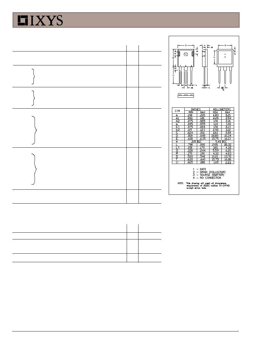
ISOPLUS247 Outline
Reverse Diode (FRED)
Characteristic Values
(T
J
= 25
°C, unless otherwise specified)
Symbol
Test Conditions
min.
typ.
max.
V
F
I
F
= 20A, V
GE
= 0 V, Note 2
2.7
V
I
RM
I
F
= 50A, V
GE
= 0 V, -di
F
/dt = 800 A/
µs
50
A
t
rr
V
R
= 600 V
150
ns
R
thJC
1.5 K/W
See IXGX32N170AH1 for
charcteristic curves