© 2001 IXYS All rights reserved
1 - 2
109
V
DSS
I
D25
R
DS(on)
600 V
38 A
70 m
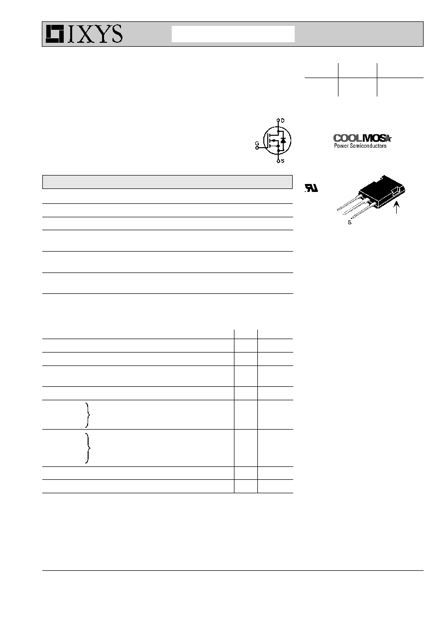
CoolMOS
Power MOSFET
in ISOPLUS247
TM
Package
N-Channel Enhancement Mode
Low R
DSon
, High V
DSS
MOSFET
Package with Electrically Isolated Base
IXKR 40N60C
Features
q
ISOPLUS247 package with DCB Base
- Electrical isolation towards the heatsink
- Low coupling capacitance to the heatsink for
reduced EMI
- High power dissipation
- High temperature cycling capability
of chip on DCB
- JEDEC TO247AD compatible
- Easy clip assembly
q
fast CoolMOS power MOSFET - 2
nd
generation
- High blocking capability
- Low on resistance
- Avalanche rated for unclamped
inductive switching (UIS)
- Low thermal resistance
due to reduced chip thickness
q
Enhanced total power density
Applications
q
Switched mode power supplies (SMPS)
q
Uninterruptible power supplies (UPS)
q
Power factor correction (PFC)
q
Welding
q
Inductive heating
Isolated base*
ISOPLUS 247
TM
E153432
G
D
G = Gate D = Drain S = Source
* Patent pending
CoolMOS is a trademark of
Infineon Technologies AG.
Advanced Technical Information
IXYS reserves the right to change limits, test conditions and dimensions.
MOSFET
Symbol
Conditions
Maximum Ratings
V
DSS
T
VJ
= 25∞C to 150∞C
600
V
V
GS
±20
V
I
D25
T
C
= 25∞C
38
A
I
D90
T
C
= 90∞C
25
A
dv/dt
V
DS
< V
DSS
; I
F
50A;
di
F
/dt
200A/µs
6
V/ns
T
VJ
= 150∞C
E
AS
I
D
= 10 A; L = 36 mH; T
C
= 25∞C
1.8
J
E
AR
I
D
= 20 A; L = 5 µH; T
C
= 25∞C
1
mJ
Symbol
Conditions
Characteristic Values
(T
VJ
= 25
∞
C, unless otherwise specified)
min.
typ.
max.
R
DSon
V
GS
= 10 V;
I
D
= I
D90
70 m
V
GSth
V
DS
= 20 V;
I
D
= 3 mA;
3.5
5.5
V
I
DSS
V
DS
= V
DSS
;
V
GS
= 0 V; T
VJ
= 25∞C
25
µA
T
VJ
= 125∞C
60
µA
I
GSS
V
GS
= ±20 V; V
DS
= 0 V
100
nA
Q
g
220
nC
Q
gs
55
nC
Q
gd
125
nC
t
d(on)
30
ns
t
r
95
ns
t
d(off)
100
ns
t
f
10
ns
V
F
(reverse conduction) I
F
= 20 A;
V
GS
= 0 V
0.9
1.1
V
R
thJC
0.45 K/W
V
GS
= 10 V; V
DS
= 350 V; I
D
= 50 A
V
GS
= 10 V; V
DS
= 380 V;
I
D
= 25 A; R
G
= 1.8
© 2001 IXYS All rights reserved
2 - 2
109
IXKR 40N60C
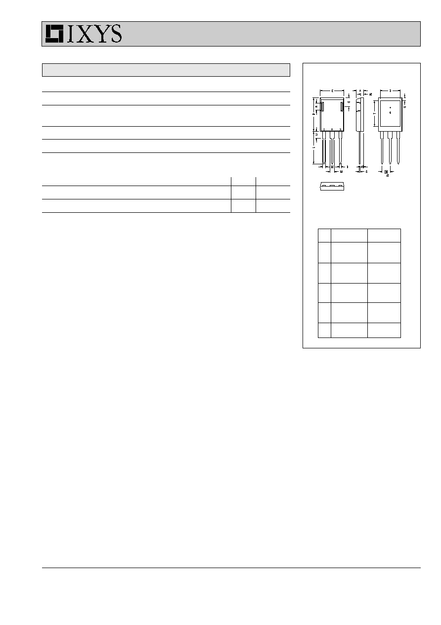
ISOPLUS 247 OUTLINE
ISOPLUS 247 OUTLINE
Dim.
Millimeter
Inches
Min.
Max.
Min. Max.
A
4.83
5.21
.190 .205
A
1
2.29
2.54
.090 .100
A
2
1.91
2.16
.075 .085
b
1.14
1.40
.045 .055
b
1
1.91
2.13
.075 .084
b
2
2.92
3.12
.115 .123
C
0.61
0.80
.024 .031
D
20.80
21.34
.819 .840
E
15.75
16.13
.620 .635
e 5.45 BSC
.215 BSC
L
19.81
20.32
.780 .800
L1
3.81
4.32
.150 .170
Q
5.59
6.20
.220 .244
R
4.32
4.83
.170 .190
1 Gate, 2 Drain (Collector)
3 Source (Emitter)
4 no connection
Component
Symbol
Conditions
Maximum Ratings
V
ISOL
I
ISOL
1 mA; 50/60 Hz
2500
V~
T
VJ
-40...+150
∞
C
T
stg
-40...+125
∞
C
T
L
1.6 mm from case for 10 s
300
∞
C
F
C
mounting force with clip
20 ... 120
N
Symbol
Conditions
Characteristic Values
min.
typ.
max.
R
thCH
with heatsink compound
0.25
K/W
Weight
6
g