1 - 3
© 2005 IXYS All rights reserved
0539
IXYS reserves the right to change limits, test conditions and dimensions.
Advanced Technical Information
IXRP 15N120
IXRA 15N120
V
CES
= ±1200 V
I
C25
= 25 A
V
CE(sat)
= 2.5 V
typ.
Features
∑ IGBT with NPT (non punch through)
structure
∑ reverse blocking capability
- function of series diode monolithically
integrated, no external series diode
required
- soft reverse recovery
∑ positive temperature coefficient of
saturation voltage
∑ Epoxy of TO-247 package meets
UL 94V-0
Applications
Converters requiring reverse blocking
capability:
- current source inverters
- matrix converters
- bi-directional switches
- resonant converters
- induction heating
- auxiliary switches for soft switching
in the main current path
IGBT
Symbol
Conditions
Maximum Ratings
V
CES
T
VJ
= 25∞C to 150∞C
±1200
V
V
GES
Continuous
± 20
V
I
C25
T
C
= 25∞C
25
A
I
C90
T
C
= 90∞C
15
A
I
CM
V
GE
= 0/15 V; R
G
= 47
; T
VJ
= 125∞C
30
A
V
CEK
RBSOA; Clamped inductive load; L = 100 µH
600
V
SCSOA
600 V
10
µs
P
tot
T
C
= 25∞C
300
W
IGBT with Reverse
Blocking capability
Symbol
Conditions
Characteristic Values
(T
VJ
= 25
∞C, unless otherwise specified)
min.
typ.
max.
V
CE(sat)
I
C
= 10 A; V
GE
= 15 V; T
VJ
= 25∞C
2.5
2.95
V
T
VJ
= 125∞C
3.3
V
V
GE(th)
I
C
= 1 mA; V
GE
= V
CE
3
6
V
I
CES
V
CE
= V
CES
;
V
GE
= 0 V; T
VJ
= 25∞C
50
µA
T
VJ
= 125∞C
1.0
mA
I
GES
V
CE
= 0 V; V
GE
=
± 20 V
500
nA
Q
Gon
V
CE
= 120 V; V
GE
= 15 V; I
C
= 10 A
36
nC
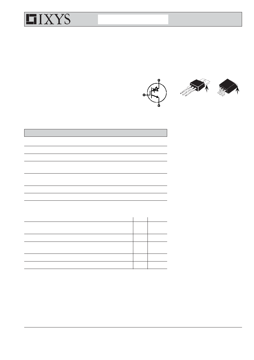
C
E
G
TO-220
G
E
G = Gate,
C = Collector,
E = Emitter,
TAB = Collector
C (TAB)
C
G
E
C
C (TAB)
TO-263
IXRP 15N120
IXRA 15N120
2 - 3
© 2005 IXYS All rights reserved
0539
IXYS reserves the right to change limits, test conditions and dimensions.
Advanced Technical Information
IXRP 15N120
IXRA 15N120
Component
Symbol
Conditions
Maximum Ratings
T
VJ
-55...+150
∞C
T
stg
-55...+125
∞C
M
d
mounting torque
0.8 - 1.2
Nm
F
C
mounting force with clip
20...120
N
Symbol
Conditions
Characteristic Values
typ.
R
thCH
with heatsink compound
0.25
K/W
Weight
6
g
IGBT
Symbol
Conditions
Characteristic Values
(T
VJ
= 25
∞C, unless otherwise specified)
typ.
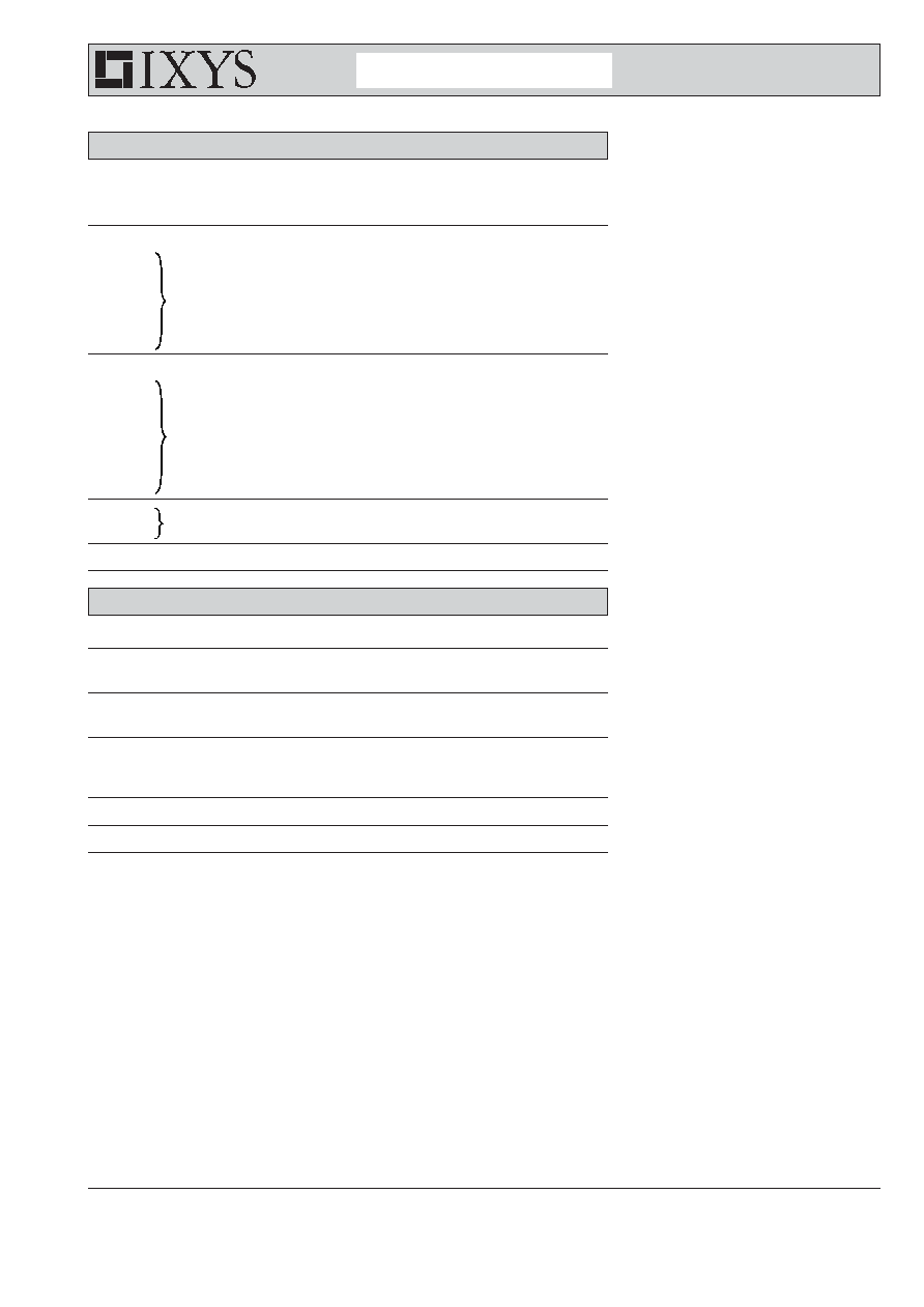
External diode DSEP 30-12 - diagramm see Fig. 1
t
d(on)
22
ns
t
r
18
ns
t
d(off)
210
ns
t
f
32
ns
E
on
1.1
mJ
E
off
0.13
mJ
Internal diode - diagramm see Fig. 2
t
d(on)
17.5
ns
t
r
16
ns
t
d(off)
212
ns
t
f
41
ns
E
on
3.0
mJ
E
off
0.1
mJ
E
rec int
0.65
mJ
I
RM
I
F
= 10 A; di
C
/dt = -800 A/µs; T
VJ
= 125∞C
25
A
t
rr
V
CE
= -600 V; V
GE
= 15 V
300
ns
R
thJC
0.65
K/W
Inductive load; T
VJ
= 125∞C
V
CE
= 600 V; I
C
= 10 A
V
GE
= ±15 V; R
G
= 47
Inductive load; T
VJ
= 125∞C
V
CE
= 600 V; I
C
= 10 A
V
GE
= ±15 V; R
G
= 47
3 - 3
© 2005 IXYS All rights reserved
0539
IXYS reserves the right to change limits, test conditions and dimensions.
Advanced Technical Information
IXRP 15N120
IXRA 15N120
U
U
Fig. 1
turn-on/turn-off with
external diode (DSEP 30-12)
Fig. 2
turn-on/turn-off with internal diode
U
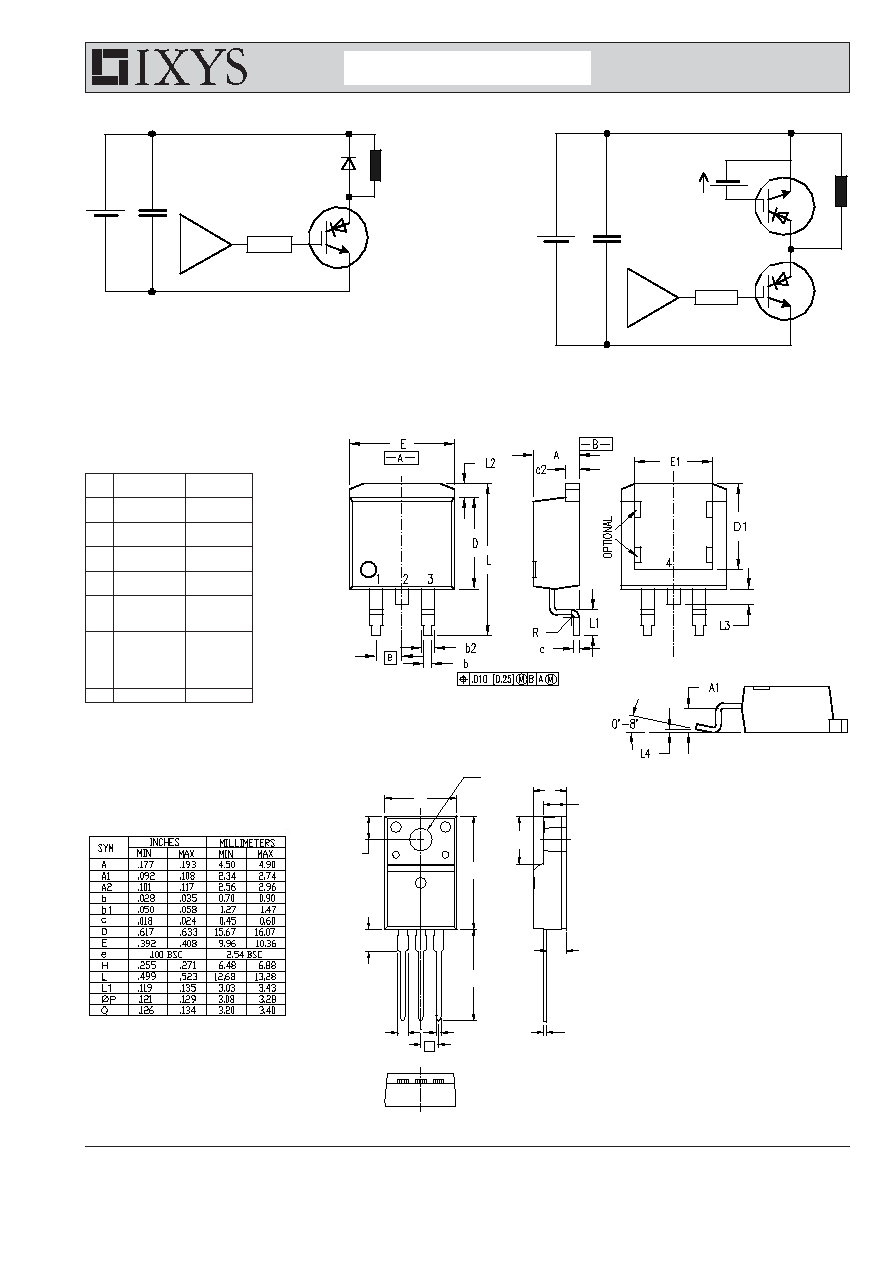
TO-220 AB Outline
ÿP
A
A1
H
A2
Q
L1
D
E
L
b
b1
c
e
TO-263 AA (D
2
PAK)
incl. middle lead
Dim.
Millimeter
Inches
Min.
Max.
Min.
Max.
A
4.06
4.83
.160
.190
A1
2.03
2.79
.080
.110
b
0.51
0.99
.020
.039
b2
1.14
1.40
.045
.055
c
0.46
0.74
.018
.029
c2
1.14
1.40
.045
.055
D
8.64
9.65
.340
.380
D1
7.11
8.13
.280
.320
E
9.65
10.29
.380
.405
E1
6.86
8.13
.270
.320
e
2.54
BSC
.100
BSC
L
14.61
15.88
.575
.625
L1
2.29
2.79
.090
.110
L2
1.02
1.68
.040
.066
L3
1.27
1.78
.050
.070
L4
0
0.38
0
.015
R
0.46
0.74
.018
.029