© 2000 IXYS All rights reserved
1 - 3
V
CES
T
VJ
= 25°C to 150°C
1200
V
V
GE
Continuous
±
20
V
I
C25
T
case
= 25°C, DC
78
A
I
C80
T
case
= 80°C, DC
52
A
I
CM
t
p
= Pulse width limited by T
VJM
140
A
P
tot
T
case
= 80°C
222
W
V
RRM
1200
V
I
F(AV)
T
case
= 80°C, rectangular d
= 0.5
27
A
I
F(RMS)
T
case
= 80°C, rectangular d = 0.5
38
A
I
FRM
T
case
= 80°C, t
P
= 10 µs, f = 5 kHz
tbd
A
I
FSM
T
VJ
= 45°C, t = 10 ms
200
A
T
VJ
= 150°C, t = 10 ms
180
A
P
tot
T
case
= 80°C
64
W
Symbol
Conditions
Maximum Ratings
I
dAV
T
case
= 80°C, sinusoidal 120°
120
A
I
FRMS
/I
TRMS
T
case
= 80°C, per leg
77
A
I
FSM
/I
TSM
T
VJ
= 25°C, t = 10 ms, V
R
= 0 V
750
A
T
VJ
= 150°C, t = 10 ms, V
R
= 0 V
670
A
I
2
t
T
VJ
= 25°C, t = 10 ms, V
R
= 0 V
2810
A
T
VJ
= 150°C, t = 10 ms, V
R
= 0V
2240
A
(di/dt)
cr
T
VJ
= T
VJM
repetitive, I
T
= 150 A
150
A/µs
f = 50 Hz, t
P
= 200 µs
V
D
=
2
/
3
V
DRM
I
G
= 0.45 A,
non repetitive, I
T
= I
d(AV)
/3
500
A/µs
di
G
/dt = 0.45 A/µs
(dv/dt)
cr
T
VJ
= T
VJM
; V
DR
=
2
/
3
V
DRM
1000
V/µs
R
GK
=
¥
; method 1 (linear voltage rise)
P
GM
T
VJ
= T
VJM
t
P
= 30 µs
10
W
I
T
= I
d(AV)
/3
t
P
= 300 µs
5
W
t
P
= 10 ms
1
W
P
GAVM
0.5
W
V
RRM
Type
V
1200
VVZB 120-12 io1
1400
VVZB 120-14 io1
1600
VVZB 120-16 io1
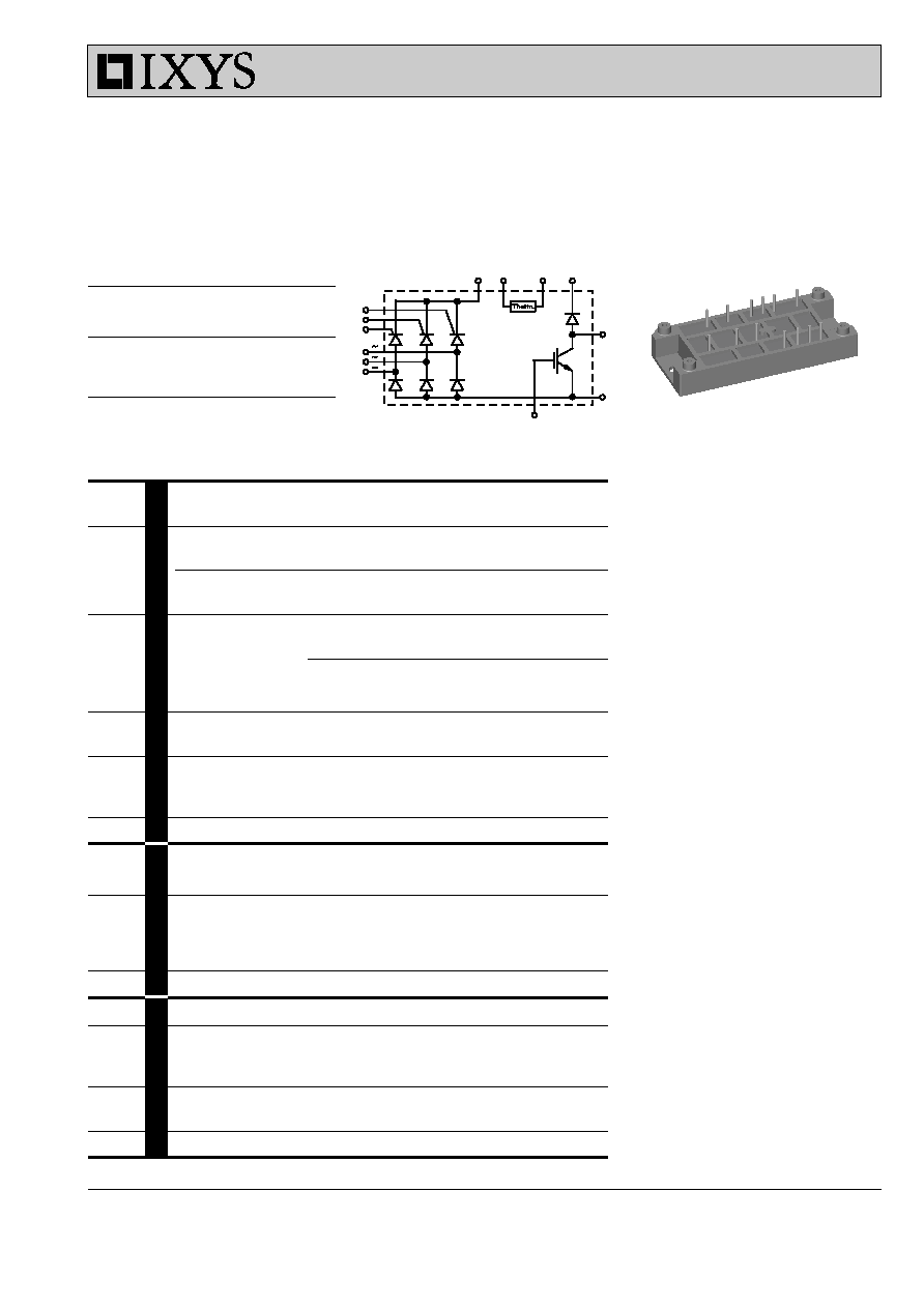
IGBT
Fast Recovery Diode
Rectifier Bridge
Features
· Soldering connections for PCB
mounting
· Isolation voltage 3600 V~
· Ultrafast freewheel diode
· Convenient package outline
Applications
· Drive Inverters with brake system
Advantages
· 2 functions in one package
· No external isolation
· Easy to mount with two screws
· Suitable for wave soldering
· High temperature and power cycling
capability
VVZB 120
Data according to IEC 60747
IXYS reserves the right to change limits, test conditions and dimensions.
031
V
RRM
= 1200-1600 V
I
dAV
= 120 A
Three Phase Half Controlled
Rectifier Bridge
with IGBT and Fast Recovery Diode
for Braking System
© 2000 IXYS All rights reserved
2 - 3
VVZB 120
Symbol
Conditions
Characteristic Values
(T
VJ
= 25°C, unless otherwise specified)
min.
typ.
max.
I
R
, I
D
V
R
= V
RRM
/V
DRM
,
0.3
mA
V
R
= V
RRM
/V
DRM
, T
VJ
= 150°C
5
mA
V
F
, V
T
I
F
= 100 A,
1.47
V
V
T0
For power-loss calculations only
0.85
V
r
T
T
VJ
= 150°C
5 m
W
V
GT
V
D
= 6 V;
T
VJ
= 25°C
1.5
V
T
VJ
= -40°C
1.6
V
I
GT
V
D
= 6 V;
T
VJ
= 25°C
100
mA
T
VJ
= -40°C
200
mA
V
GD
T
VJ
= T
VJM
; V
D
=
2
/
3
V
DRM
0.2
V
I
GD
T
VJ
= T
VJM
; V
D
=
2
/
3
V
DRM
10
mA
I
L
V
D
= 6 V; t
G
= 30 µs
450
mA
di
G
/dt = 0.45 A/µs; I
G
= 0.45 A
I
H
T
VJ
= T
VJM
; V
D
= 6 V; R
GK
=
¥
200
mA
t
gd
V
D
= ½ V
DRM
2
µs
di
G
/dt = 0.45 A/µs; I
G
= 0.45 A
t
q
T
VJ
= T
VJM
; V
R
= 100 V; V
D
=
2
/
3
V
DRM
; t
P
= 200 µs
150
µs
dv/dt = 10 V/µs; I
T
= 120 A; -di/dt = 10 A/µs
Q
S
T
VJ
= T
VJM
90
µC
I
RM
-di/dt = 0.64 A/µs; I
T
/I
F
= 50 A
11
A
R
thJC
per thyristor / diode; sine 120° el.
1 K/W
R
thJH
per thyristor / diode; sine 120° el.
1.3 K/W
V
BR(CES)
V
GS
= 0 V, I
C
= 1 mA
1200
V
V
GE(th)
I
C
= 10 mA
5
8
V
I
GES
V
GE
=
±
20 V
500
nA
I
CES
V
CE
= 0.8 V
CES
0.5
mA
V
CE
= 0.8 V
CES
,T
VJ
=
150°C
3
mA
V
CEsat
V
GE
= 15 V, I
C
= 50 A
3.35
V
t
SC
V
GE
= 15 V, V
CE
= 0.6 V
CES
, T
VJ
=
125°C,
10
µs
(SCSOA)
R
G
= 11
W
, non repetitive
RBSOA
V
GE
= 15 V, V
CE
= 0.8 V
CES
, T
VJ
=
125°C,
100
A
R
G
= 11
W
, Clamped Inductive load, L = 100 µH
C
ies
V
CE
= 25 V, f = 1 MHz, V
GE
= 0 V
9
nF
t
d(on)
65
ns
t
d(off)
200
ns
t
ri
tbd
ns
t
fi
tbd
ns
E
on
4.1
mJ
E
off
5.7
mJ
R
thJC
0.32 K/W
R
thJH
0.45 K/W
IGBT
Rectifier Bridge
V
CE
= 0.6 V
CES
, I
C
= 25 A
V
GE
= 15 V, R
G
= 11
W
Inductive load; L = 100 µH
T
VJ
=
125°C
© 2000 IXYS All rights reserved
3 - 3
VVZB 120
Symbol
Conditions
Characteristic Values
(T
VJ
= 25°C, unless otherwise specified)
min.
typ.
max.
I
R
V
R
= V
RRM
,
T
VJ
= 25°C
0.75
mA
V
R
= 0.8 V
RRM
,T
VJ
= 150°C
3
7
mA
V
F
I
F
= 30 A,
T
VJ
= 25°C
2.55
V
V
T0
For power-loss calculations only
1.65
V
r
T
T
VJ
= 150°C
18.2 m
W
I
RM
I
F
= 30 A,
-di
F
/dt = 240 A/µs
16
18
A
V
R
= 100 V
t
rr
I
F
= 1 A,
-di
F
/dt = 100 A/µs
40
60
ns
V
R
= 30 V
R
thJC
1.1 K/W
R
thJH
1.5 K/W
Common Specification
Maximum Ratings
T
VJ
-40...+150
°C
T
VJM
150
°C
T
stg
-40...+125
°C
V
ISOL
50/60 Hz
t = 1 min
3000
V~
I
ISOL
£
1 mA
t = 1 s
3600
V~
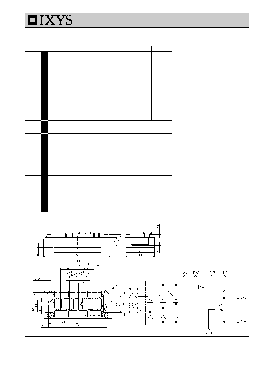
M
d
Mounting torque
(M5)
2-2.5
Nm
(10-32 unf)
18-22
lb.in.
Weight
typ.
80
g
d
S
Creep distance on surface
12.7
mm
d
A
Strike distance in air
11
mm
a
Maximum allowable acceleration
50
m/s
2
R
25
Thermistor
2.1
k
W
B
25/100
3560
K
Fast Recovery Diode
Module
Dimensions in mm (1 mm = 0.0394")