 | ÐлекÑÑоннÑй компоненÑ: LTC3035 | СкаÑаÑÑ:  PDF PDF  ZIP ZIP |
3035f.pm65
LTC3035
1
3035f
Wide Input Voltage Range: 1.7V to 5.5V
Wide Adjustable Output Voltage Range:
0.4V to 3.6V
Built-In Charge Pump Generates High Side Bias
Very Low Dropout: 45mV at 300mA
±
2% Voltage Accuracy Over Temperature,
Supply, Load
Fast Transient Recovery
Low Operating Current: I
IN
= 100
µA Typ
Low Shutdown Current: I
IN
= 1
µA Typ
Stable with Ceramic Capacitor Down to 1
µF
Output Current Limit
Thermal Overload Protected
Reverse Output Current Protected
Available in 8-Lead (3mm
× 2mm) DFN Package
TYPICAL APPLICATIO
U
FEATURES
DESCRIPTIO
U
The LTC
®
3035 is a micropower, VLDOTM (very low drop-
out) linear regulator which operates from input voltages as
low as 1.7V. The device is capable of supplying 300mA of
output current with a typical dropout voltage of only
45mV. To allow operation at low input voltages the LTC3035
includes a charge pump generator that provides the nec-
essary bias voltage for the internal LDO circuitry. Output
current comes directly from the input supply for high
efficiency regulation. The charge pump bias generator
requires only a 0.1
µF flying capacitor and a 1µF bypass
capacitor for operation. The low 0.4V internal reference
voltage allows the LTC3035 to be programmed to much
lower output voltages than commonly available in LDOs.
The output voltage is programmed via two tiny SMD
resistors. The LTC3035's low quiescent current makes it
an ideal choice for use in battery-powered systems.
Other features include high output voltage accuracy, ex-
cellent transient response, stability with ultralow ESR
ceramic capacitors as small as 1
µF, short-circuit and
thermal overload protection, output current limiting and
reverse output current protection. The LTC3035 is avail-
able in a tiny, low profile (3mm
× 2mm × 0.75mm) 8-lead
DFN package.
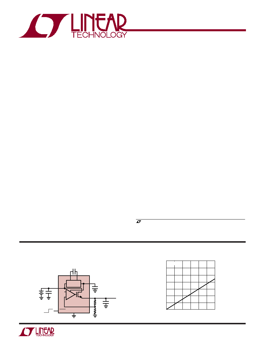
300mA VLDO Linear
Regulator with Charge Pump
Bias Generator
APPLICATIO S
U
Li-Ion to 3.3V Low Dropout Supplies
2
× AA to 1.8V Low Dropout Supplies
Low Power Handheld Devices
Low Voltage Logic Supplies
DSP Power Supplies
Cellular Phones
Portable Electronic Equipment
Handheld Medical Instruments
Post Regulator for Switching Supply Noise Rejection
3.3V Output Voltage from Li-Ion Battery
, LTC and LT are registered trademarks of Linear Technology Corporation.
VLDO is a trademark of Linear Technology Corporation.
All other trademarks are the property of their respective owners.
Protected by U.S. Patents, including 6411531, others pending.
I
OUT
(mA)
0
70
60
50
40
30
20
10
0
150
250
3035 TA01b
50
100
200
300
DROPOUT VOLTAGE (mV)
T
A
= 25
°C
Dropout Voltage vs Load Current
CP
0.4V
IN
SHDN
GND
Li-Ion
BATTERY
3.4V TO 4.2V
1
µF
0.1
µF
C
BIAS
1
µF
C
OUT
1
µF
3035 TA01a
294k
40.2k
V
OUT
3.3V
300mA
OFF ON
CM
BIAS
OUT
ADJ
BIAS
GENERATOR
LTC3035
+
LTC3035
2
3035f
Order Options Tape and Reel: Add #TR
Lead Free: Add #PBF Lead Free Tape and Reel: Add #TRPBF
Lead Free Part Marking:
http://www.linear.com/leadfree/
ABSOLUTE AXI U
RATI GS
W
W
W
U
PACKAGE/ORDER I FOR ATIO
U
U
W
(Notes 1, 2)
V
IN
to GND .................................................. 0.3V to 6V
SHDN to GND ............................................. 0.3V to 6V
CP, CM, BIAS to GND ................................. 0.3V to 6V
ADJ to GND ................................................ 0.3V to 6V
V
OUT
to GND ............................................... 0.3V to 6V
Operating Junction Temperature
(Note 3) ........................................... 40
°C to 125°C
Storage Temperature Range ................ 65
°C to 125°C
Output Short Circuit Duration .......................... Indefinite
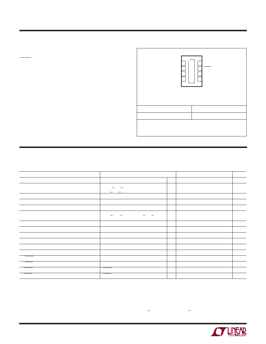
ORDER PART NUMBER
Consult LTC Marketing for parts specified with wider operating temperature ranges.
LTC3035EDDB
TOP VIEW
9
DDB PACKAGE
8-LEAD (3mm
× 2mm) PLASTIC DFN
5
6
7
8
4
3
2
1
CP
CM
GND
IN
BIAS
SHDN
ADJ
OUT
T
JMAX
= 125
°C,
JA
= 76
°C/W
EXPOSED PAD (PIN 9) IS GND,MUST BE SOLDERED TO PCB
DDB PART MARKING
LBRM
ELECTRICAL CHARACTERISTICS
The
denotes specifications which apply over the full specified temperature
range, otherwise specifications are at T
A
= 25
°
C. V
IN
= 3.6V, V
OUT
= 3.3V, C
FLY
= 0.1
µ
F, C
OUT
= 1
µ
F, C
IN
= 1
µ
F, C
BIAS
= 1
µ
F (all
capacitors ceramic) unless otherwise noted.
PARAMETER
CONDITIONS
MIN
TYP
MAX
UNITS
V
IN
Operating Voltage (Note 4)
1.7
5.5
V
V
BIAS
Output Voltage Range
2.63V < V
IN
< 5.5V
4.8
5
5.3
V
1.7V < V
IN
< 2.63V
1.85 · V
IN
1.90 · V
IN
1.95 · V
IN
V
V
OUT
Output Voltage Range
V
ADJ
3.6
V
V
IN
Operating Current
I
OUT
= 10
µA
100
200
µA
V
IN
Shutdown Current
V
SHDN
= 0V
1
5
µA
V
ADJ
Regulation Voltage (Note 5)
1mA < I
OUT
< 300mA, 1.7V < V
IN
< 5.5V,
0.392
0.4
0.408
V
V
OUT
= 1.5V
I
ADJ
ADJ Input Current
V
ADJ
= 0.4V
50
0
50
nA
OUT Load Regulation (Referred to ADJ Pin)
I
OUT
= 1mA to 300mA
0.2
mV
Dropout Voltage (Note 6)
V
IN
= 1.7V, V
ADJ
= 0.37V, I
OUT
= 300mA
45
100
mV
I
OUT
Continuous Output Current
300
mA
I
OUT
Short Circuit Output Current
V
ADJ
= V
OUT
= 0
760
mA
V
OUT
Output Noise Voltage
F = 10Hz to 100kHz, I
OUT
= 150mA
150
µVrms
V
IH
SHDN Input High Voltage
1.1
V
V
IL
SHDN Input Low Voltage
0.3
V
I
IH
SHDN Input High Current
SHDN = V
IN
1
1
µA
I
IL
SHDN Input Low Current
SHDN = 0V
1
1
µA
Note 1: Absolute Maximum Ratings are those values beyond which the life
of a device may be impaired.
Note 2: This IC includes overtemperature protection that is intended to
protect the device during momentary overload conditions. Junction
temperature will exceed 125
°C when overtemperature protection is active.
Continuous operation above the specified maximum operating junction
temperature may impair device reliability.
Note 3: The LTC3035 regulator is tested and specified under pulse load
conditions such that T
J
T
A
. The LTC3035 is 100% production tested at
25
°C. Performance at 40°C and 125°C is assured by design,
characterization and correlation with statistical process control.
Note 4: Min Operating Input Voltage required for regulation is:
V
IN
> V
OUT
+ V
DROPOUT
and V
IN
> 1.7V
LTC3035
3
3035f
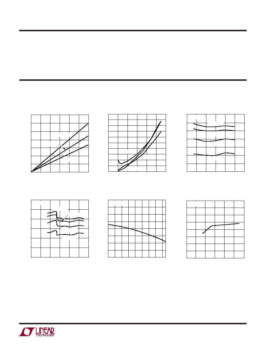
TYPICAL PERFOR A CE CHARACTERISTICS
U
W
Dropout Voltage vs Load Current
ADJ Voltage vs Input Voltage
ADJ Voltage vs Temperature
V
IN
Shutdown Current
V
IN
No Load Operating Current
V
IN
No Load Operating Current
I
OUT
(mA)
0
70
60
50
40
30
20
10
0
150
250
3035 G01
50
100
200
300
DROPOUT VOLTAGE (mV)
T
A
= 125
°C
T
A
= 40
°C
T
A
= 25
°C
V
IN
(V)
0
0
I
IN
(
µ
A)
1.0
2.0
3.0
1
2
3
4
LT1108 · TPC12
5
4.0
5.0
0.5
1.5
2.5
3.5
4.5
6
T
A
= 40
°C
T
A
= 85
°C
T
A
= 25
°C
V
IN
(V)
3
115
110
105
100
95
90
85
80
4.5
5.5
3035 G03
3.5
4
5
6
I
IN
(
µ
A)
V
OUT
= 3.3V
T
A
= 40
°C
T
A
= 25
°C
T
A
= 85
°C
T
A
= 125
°C
V
IN
(V)
0
60
I
IN
(
µ
A)
70
80
90
100
120
1
2
3
4
3035 G04
5
6
110
V
OUT
= 1.5V
T
A
= 40
°C
T
A
= 25
°C
T
A
= 125
°C
T
A
= 85
°C
TEMPERATURE (
°C)
45
396
ADJUST VOLTAGE (mV)
397
399
400
401
402
403
5
35
55
3035 G05
398
25
15
75
95
115
404
V
OUT
= 3.3V
V
IN
(V)
0
ADJ VOLTAGE (mV)
4
3035 G06
2
1
5
3
6
404
403
402
401
400
399
398
397
396
V
OUT
= 1.5V
ELECTRICAL CHARACTERISTICS
Note 5: Operating conditions are limited by maximum junction
temperature. The regulated output voltage specification will not apply for
all possible combinations of input voltage and output current. When
operating at maximum input voltage, the output current range must
be limited.
Note 6: Dropout voltage is minimum input to output voltage differential
needed to maintain regulation at a specified output current. In dropout, the
output voltage will be equal to V
IN
V
DROPOUT
.
LTC3035
4
3035f
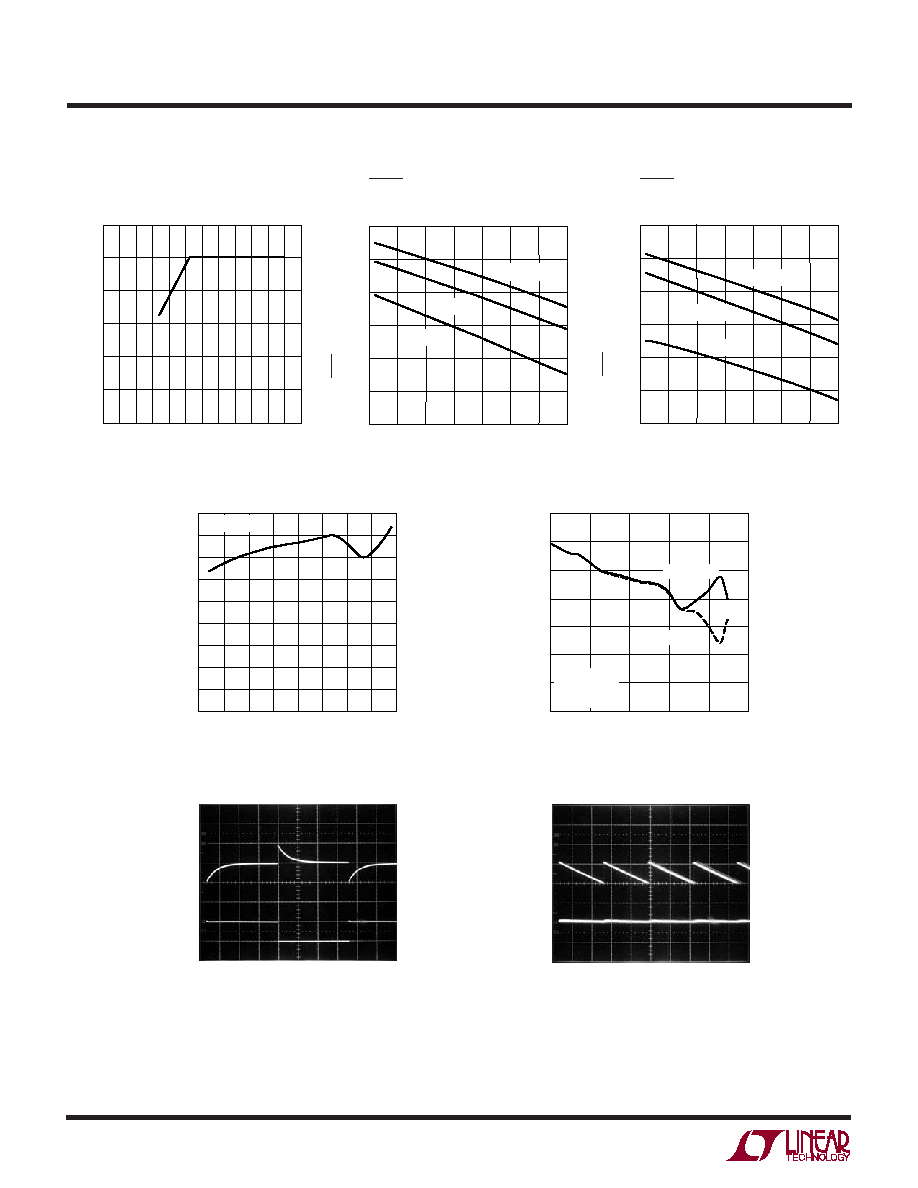
TYPICAL PERFOR A CE CHARACTERISTICS
U
W
V
IN
Ripple Rejection vs Frequency
Current Limit vs Input Voltage
V
IN
(V)
1.5
CURRENT LIMIT (mA)
500
600
700
5.5
5
3035 G10
400
300
0
2
3
4
2.5
3.5
4.5
100
200
900
800
V
OUT
= 0V
Transient Response
V
OUT
20mV/DIV
AC
I
OUT
300mA
200
µs/DIV
V
IN
= 3.6V
V
OUT
= 3.3V
C
OUT
= 1
µF
3035 G11
10mA
BIAS Output Ripple
V
BIAS
50mV/DIV
AC
V
OUT
5mV/DIV
AC
500
µs/DIV
V
IN
= 3.6V
V
OUT
= 3.3V
C
BST
= 1
µF
C
FLY
= 0.1
µF
C
OUT
= 1
µF
I
OUT
= 1mA
3035 G12
FREQUENCY (Hz)
100
50
60
70
1M
3035 G13
40
30
1k
10k
100k
10M
20
10
0
REJECTION (dB)
C
OUT
= 10
µF
V
IN
= 3.6V
V
OUT
= 3.3V
I
OUT
= 100mA
C
OUT
= 1
µF
BIAS Voltage vs Input Voltage
SHDN Threshold (Rising)
vs Temperature
SHDN Threshold (Falling)
vs Temperature
V
IN
(V)
0
0
BIAS VOLTAGE (V)
1
2
3
4
6
1
2
3
4
3035 G07
5
0.5
1.5
2.5
3.5
4.5
5.5 6
5
TEMPERATURE (
°C)
45
400
SHDN THRESHOLD (mV)
500
700
1000
5
55
80
3035 G08
600
900
800
20
30
105
130
V
IN
= 1.7V
V
IN
= 3.6V
V
IN
= 5.5V
TEMPERATURE (
°C)
45
400
SHDN THRESHOLD (mV)
500
700
1000
5
55
80
3035 G09
600
900
800
20
30
105
130
V
IN
= 1.7V
V
IN
= 3.6V
V
IN
= 5.5V
LTC3035
5
3035f
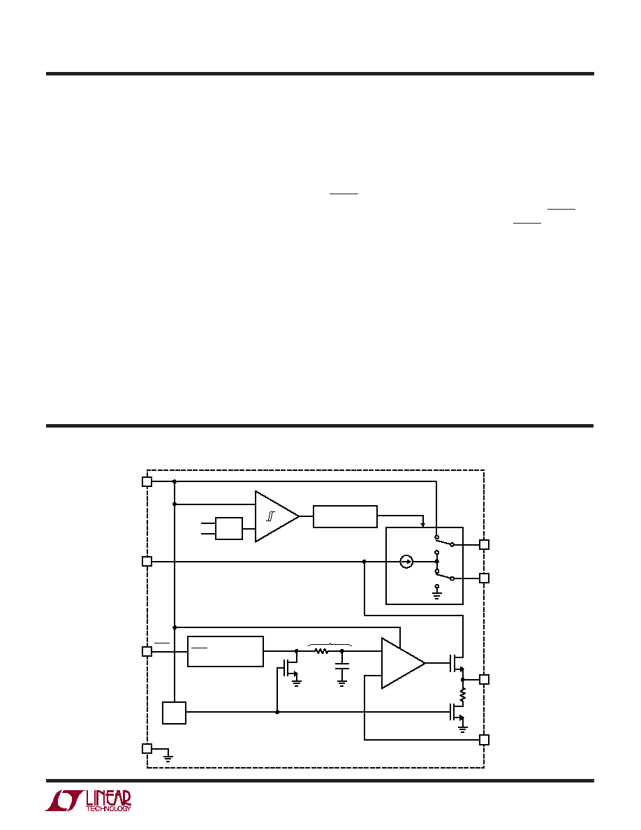
BLOCK DIAGRA
W
BIAS
UVLO
+
+
BIAS
5V
1.9 · V
IN
CP
800kHz
OSCILLATOR
CHARGE
PUMP
EN
REFERENCE
SHDN
0.400V
SOFT-START
BIAS
2.5k
8
1
CM
2
OUT
5
ADJ
6
V
MIN
V
IN
4
SHDN
7
GND
PINS 3, 9
3035 BD
U
U
U
PI FU CTIO S
CP (Pin 1): Flying Capacitor Positive Terminal.
CM (Pin 2): Flying Capacitor Negative Terminal.
GND (Pin 3): Ground. Connect to a ground plane.
IN (Pin 4): Input Supply Voltage. The output load current
is supplied directly from IN. The IN pin should be locally
bypassed to ground if the LTC3035 is more than a few
inches away from another source of bulk capacitance. In
general, the output impedance of a battery rises with
frequency, so it is usually adviseable to include an input
bypass capacitor when supplying IN from a battery. A
capacitor of 1
µF is usually sufficient.
OUT (Pin 5): Regulated Output Voltage. The OUT pin
supplies power to the load. A minimum ceramic output
capacitor of at least 1
µF is required to ensure stability.
Larger output capacitors may be required for applications
with large transient loads to limit peak voltage transients.
See the Applications Information section for more infor-
mation on output capacitance.
ADJ (Pin 6): Adjust Input Pin. This is the input to the error
amplifier. The ADJ pin reference voltage is 0.4V referenced
to ground. The output voltage range is 0.4V to 3.6V and is
set by connecting ADJ to a resistor divider from OUT to
GND.
SHDN (Pin 7): Shutdown Input, Active Low. This pin is
used to put the LTC3035 into shutdown. The SHDN pin
current is typically less than 10nA. The SHDN pin cannot
be left floating and must be tied to a valid logic level if
not used.
BIAS (Pin 8): BIAS Output Voltage Pin. BIAS is the output
of the charge pump and provides the high side supply for
the LTC3035 LDO circuitry. This pin should be locally
bypassed to ground by a 1
µF or greater capacitor as close
as possible to the pin. Nothing else should be connected
to this pin.
Exposed Pad (Pin 9): Ground and Heat Sink. Must be
soldered to PCB ground plane or large pad for optimal
thermal performance.


