 | –≠–ª–µ–∫—Ç—Ä–æ–Ω–Ω—ã–π –∫–æ–º–ø–æ–Ω–µ–Ω—Ç: AT90-1283 | –°–∫–∞—á–∞—Ç—å:  PDF PDF  ZIP ZIP |
Digital Attenuator, 15.5 dB, 5-Bit,
TTL Driver, DC-3.5 GHz
AT90
-
1283
CSP-1
V 4.00
Electrical Specifications
T
A
= +25∞C
Parameter
Test Conditions
Frequency Units
Min
Typical
Max
Insertion Loss
--
DC - 3.5 GHz
dB
--
2.8
3.2
Attenuation
Accuracy
Individual Bits 0.5-1-4-8 dB
Individual Bit 2 dB
Any Combination of Bits
1 to 15.5 dB
DC - 3.5 GHz
DC - 3.5 GHz
DC - 3.5 GHz
dB
dB
dB
--
--
--
--
--
--
±(.3 +5% of atten setting)
±(.4 +10% of atten setting)
±(.5 +7% of atten setting)
VSWR
Full Range
DC - 3.5 GHz Ratio
--
1.6:1
1.8:1
Switching Speed
50% Cntl to 90%/10% RF
10% to 90% or 90% to 10%
--
--
nS
nS
--
--
75
20
150
50
1 dB Compression
--
--
50 MHz
0.5 - 3.5 GHz
dBm
dBm
--
--
+21
+29
--
--
Input IP
3
Two-tone inputs up to +5 dBm
50 MHz
0.5-3.5 GHz
dB
dB
--
--
+35
+48
--
--
+Vcc
--
--
V
4.75
5.0
5.25
Logic "0"
Sink Current is 20 µA max.
--
V
0.0
--
0.8
Logic "1"
Source Current is 20 µA max.
--
V
2.0
--
5.0
Icc
Vcc min to max, Logic "0" or
"1"
--
mA
--
6
10
Features
n
Attenuation: 0.5 dB Steps to 15.5 dB
n
Single Positive Supply
n
Contains Internal DC to DC Converter
n
Low DC Power Consumption
n
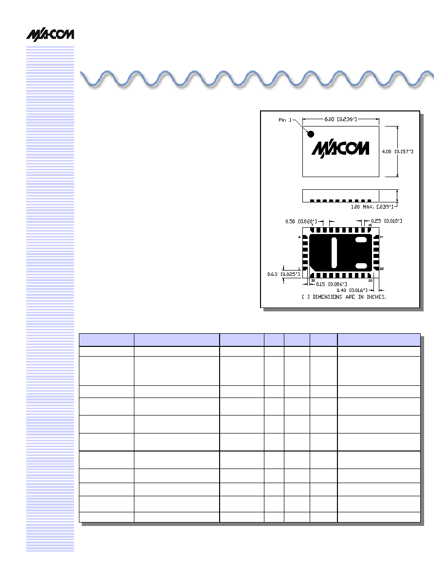
Small Footprint, JEDEC Package
n
Integral TTL Driver
n
50 ohm Impedance
Description
M/A-COM's AT90-1283 is a GaAs FET 5-bit digital
attenuator with integral TTL driver. Step size is 0.5 dB
providing a 15.5 dB total attenuation range. This device is
in an FQFP-N plastic surface mount package. The AT90-
1283 is ideally suited for use where accuracy, fast speed,
very low power consumption and low costs are required.
Digital Attenuator, 15.5 dB, 5-Bit, TTL Driver, DC - 3.5 GHz
AT90-1283
Specifications subject to change without notice.
n
North America: Tel. (800) 366-2266
n
Asia/Pacific: Tel.+81-44-844-8296, Fax +81-44-844-8298
n
Europe: Tel. +44 (1344) 869 595, Fax+44 (1344) 300 020
Visit www.macom.com for additional data sheets and product information.
V 4.00
2
Absolute Maximum Ratings
8
Parameter
Absolute Maximum
Max. Input Power
0.05 GHz
0.5 - 3.5 GHz
+27 dBm
+34 dBm
+Vcc
+5.5V
Logic Voltages
9
-0.5 to +Vcc + 0.5V
Operating Temperature
-40∞C to +85∞C
Storage Temperature
-65∞C to +125∞C
8. Operation of this device above any one of these
parameters may cause permanent damange.
9. Standard CMOS TTL interface, latch-up will occur if logic
signal is applied prior to power supply.
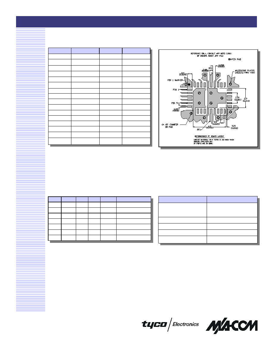
Recommended PCB Layout
7
Truth Table
0 = TTL Low; 1 = TTL High
Pin Configuration
Pin #
Function
Pin #
Function
1
GND
17
NC
2
C8
18
NC
3
C4
19
+Vcc
2
4
C2
20
NC
5
C1
21
Cp
4
6
C0.5
22
NC
7
GND
23
Cp
4
8
NC
24
NC
9
NC
25
-Vee
3,5
10
NC
1
26
GND
11
GND
27
RF2
12
RF1
28
GND
13
GND
29
NC
1
14
NC
30
-Vee
3,5
15
NC
31
NC
16
NC
32
+Vcc
2,6
1.
Pins 10 & 29 must be isolated
2.
Pin 19 must be connected to Pin 32.
3.
Pin 25 must be connected to Pin 30.
4.
.01 µF cap must be between pins 21 & 23.
5.
-Vee
produced internally and requires a .1 µF cap to GND.
6.
+Vcc requires a .1 µF cap to GND.
C8
C4
C2
C1
C0.5
Attenuation
0
0
0
0
0
Loss, Reference
0
0
0
0
1
0.5 dB
0
0
0
1
0
1.0 dB
0
0
1
0
0
2.0 dB
0
1
0
0
0
4.0 dB
1
0
0
0
0
8.0 dB
1
1
1
1
1
15.5 dB
7. Application Note C2083 is available on line at
www.macom.com
Digital Attenuator, 15.5 dB, 5-Bit, TTL Driver, DC - 3.5 GHz
AT90-1283
Specifications subject to change without notice.
n
North America: Tel. (800) 366-2266
n
Asia/Pacific: Tel.+81-44-844-8296, Fax +81-44-844-8298
n
Europe: Tel. +44 (1344) 869 595, Fax+44 (1344) 300 020
Visit www.macom.com for additional data sheets and product information.
V 4.00
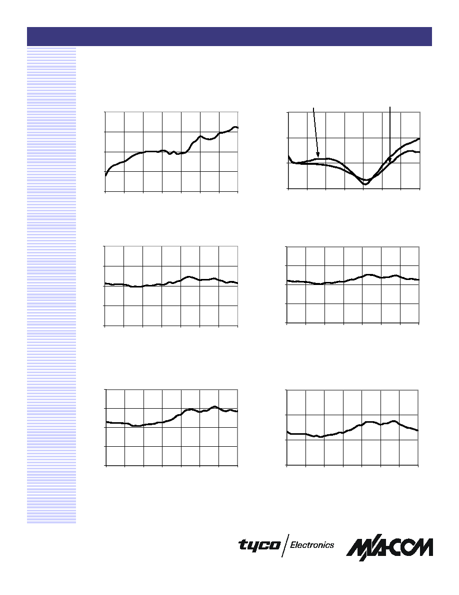
Typical Performance Curves
3
Attenuation Error, 1 dB Bit
Attenuation Error, 0.5 dB Bit
Attenuation Error, 2 dB Bit
Attenuation Error, 4 dB Bit
-1.0
-0.5
0.0
0.5
1.0
0
500
1000
1500
2000
2500
3000
3500
Frequency (MHz)
Error (dB)
-1.0
-0.5
0.0
0.5
1.0
0
500
1000
1500
2000
2500
3000
3500
Frequency (MHz)
Error (dB)
-1.0
-0.5
0.0
0.5
1.0
0
500
1000
1500
2000
2500
3000
3500
Frequency (MHz)
Error (dB)
-0.5
0.0
0.5
1.0
0
500
1000
1500
2000
2500
3000
3500
Frequency (MHz)
Error (dB)
VSWR @ Insertion Loss
Insertion Loss
1.0
1.5
2.0
2.5
3.0
0
500
1000
1500
2000
2500
3000
3500
Frequency (MHz)
Loss (dB)
1.00
1.25
1.50
1.75
0
500
1000
1500
2000
2500
3000
3500
Frequency (MHz)
VSWR Ratio
Input
Output

Digital Attenuator, 15.5 dB, 5-Bit, TTL Driver, DC - 3.5 GHz
AT90-1283
Specifications subject to change without notice.
n
North America: Tel. (800) 366-2266
n
Asia/Pacific: Tel.+81-44-844-8296, Fax +81-44-844-8298
n
Europe: Tel. +44 (1344) 869 595, Fax+44 (1344) 300 020
Visit www.macom.com for additional data sheets and product information.
V 4.00
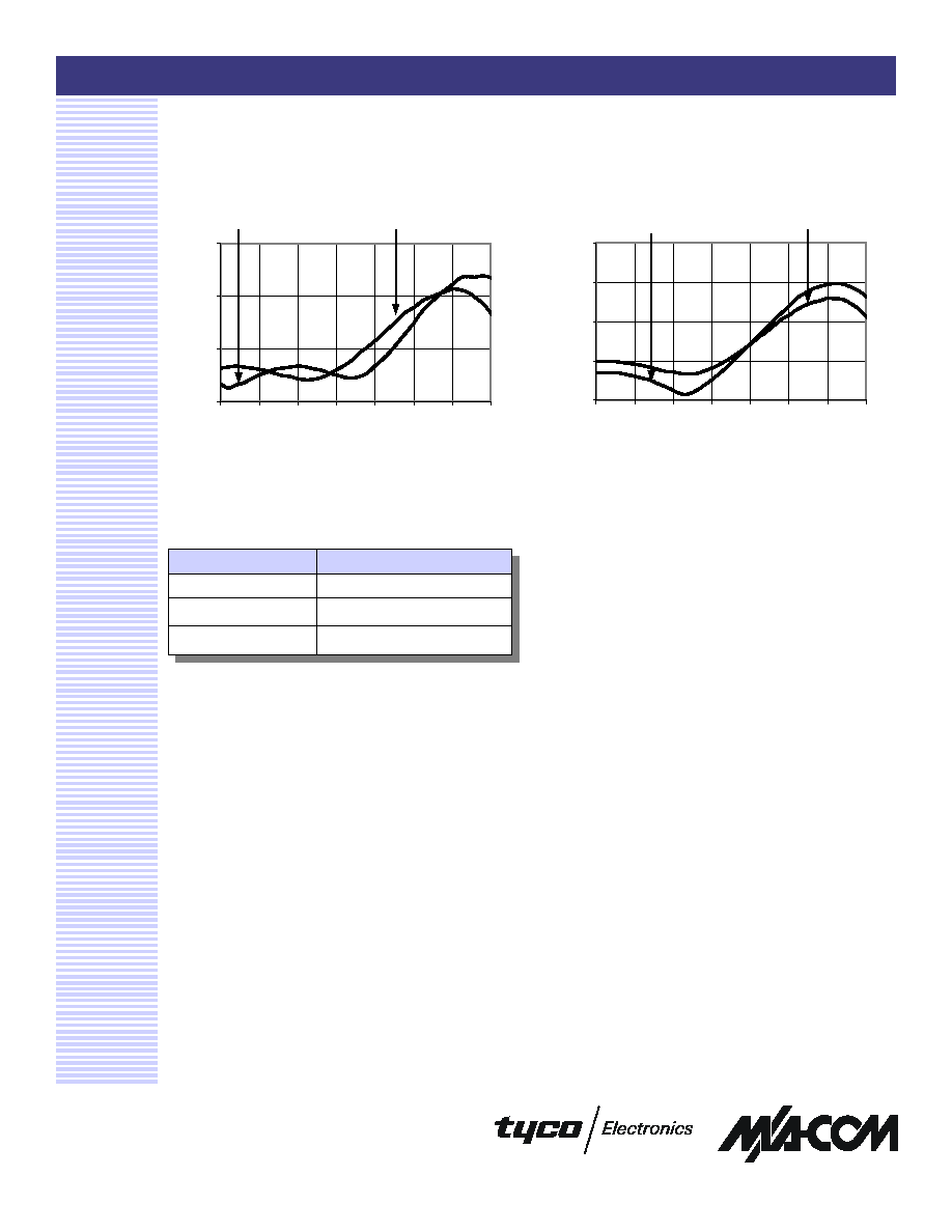
Typical Performance Curves
4
Attenuation Error, 8 dB Bit
Attenuation Error, Max. Attenuation
-0.5
0.0
0.5
1.0
0
500
1000
1500
2000
2500
3000
3500
Frequency (MHz)
Error (dB)
-1.0
0.0
1.0
2.0
3.0
0
500
1000
1500
2000
2500
3000
3500
Frequency (MHz)
Error (dB)
VSWR, 1 dB Bit
VSWR, 0.5 dB Bit
VSWR, 2 dB Bit
VSWR, 4 dB Bit
1.0
1.2
1.4
1.6
0
500
1000
1500
2000
2500
3000
3500
Frequency (MHz)
VSWR Ratio
Input
Output
1.0
1.2
1.4
1.6
0
500
1000
1500
2000
2500
3000
3500
Frequency (MHz)
VSWR Ratio
Input
Output
1.0
1.2
1.4
1.6
1.8
0
500
1000
1500
2000
2500
3000
3500
Frequency (MHz)
VSWR Ratio
Input
Output
1.0
1.2
1.4
1.6
0
500
1000
1500
2000
2500
3000
3500
Frequency (MHz)
VSWR Ratio
Input
Output
Digital Attenuator, 15.5 dB, 5-Bit, TTL Driver, DC - 3.5 GHz
AT90-1283
Specifications subject to change without notice.
n
North America: Tel. (800) 366-2266
n
Asia/Pacific: Tel.+81-44-844-8296, Fax +81-44-844-8298
n
Europe: Tel. +44 (1344) 869 595, Fax+44 (1344) 300 020
Visit www.macom.com for additional data sheets and product information.
V 4.00
Typical Performance Curves
5
Ordering Information
Part Number
Package
AT90-1283
Bulk Packaging
AT90-1283TR
Tape and Reel (1K Reel)
AT90-1283-TB
Units Mounted on Test Board
VSWR, 8 dB Bit
VSWR, Maximum Attenuation
1.0
1.2
1.4
1.6
0
500
1000
1500
2000
2500
3000
3500
Frequency (MHz)
VSWR Ratio
Input
Output
1.0
1.2
1.4
1.6
1.8
0
500
1000
1500
2000
2500
3000
3500
Frequency (MHz)
VSWR Ratio
Input
Output