M/A-COM
n
North America: Tel. (800) 366-2266, Fax (800) 618-8883
n
Asia/Pacific: Tel.+85 2 2111 8088, Fax +85 2 2111 8087
n
Europe: Tel. +44 (1344) 869 595, Fax+44 (1344) 300 020
www.macom.com
Specifications subject to change without notice.
V1.01
Features
∑
Small Size and Low Profile
∑
Industry Standard SOT-26 SMT Plastic Package
∑
Typical Isertion Loss: 0.6dB
∑
Typical Isolation: 15dB
∑
1 Watt Power Handling
Description
M/A-COM's DS52-0008 is an IC-based monolithic power divider
using M/A-COM's GMIC technology in a low cost SOT-26
plastic package. This 2-way power divider is ideally suited for
applications where small size, low insertion loss, superior phase/
amplitude tracking and low cost are required. Typical
applications include personal communications systems and other
communication applications where size and PCB real estate are at
a premium. Available in Tape and Reel.
The DS52-0008 is fabricated using a passive-integrated circuit
process. The process features full-chip passivation for increased
performance and reliability.
Typical Electrical Specifications
1
, T
A
= +25∞C
Parameter
Units
Min
Typ
Max
Insertion Loss above 3.0dB
dB
--
0.6
0.8
Isolation
dB
13
15
--
VSWR RF Input
--
--
1.3 : 1
1.4 : 1
Amplitude Balance
dB
--
0.1
0.25
Phase Balance
Degrees
--
3.0
5.0
1. All specifications apply with a 50-Ohm source and load impedance.
Low Cost Two-Way GMIC SMT Power Divider
824 - 960 MHz
DS52-0008
Ordering Information
Part Number
Package
DS52-0008
SOT-26 Lead Plastic Package
DS52-0008-TR
Forward Tape and Reel
1
DS52-0008-RTR
Reverse Tape and Reel
1
1. If specific reel size is required, consult factory for part number
assignment.
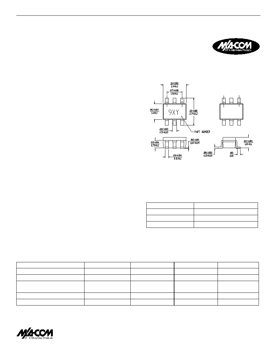
SOT-26

M/A-COM
n
North America: Tel. (800) 366-2266, Fax (800) 618-8883
n
Asia/Pacific: Tel.+85 2 2111 8088, Fax +85 2 2111 8087
n
Europe: Tel. +44 (1344) 869 595, Fax+44 (1344) 300 020
www.macom.com
Specifications subject to change without notice.
V1.01
Phase Balance vs. Frequency
(Relative to RF1)
-5
-4
-3
-2
-1
0
824
858
892
926
960
Frequency MHz
Phase, degrees
1. Exceeding these limits may cause permanent damage.
2. With internal load dissipation of 0.125 W Maximum.
Absolute Maximum Ratings
1
Parameter
Absolute Maximum
Input Power
2
1 W CW
Operating Temperature
-40∞C to +85∞C
Storage Temperature
-65∞C to +150∞C
Typical Performance
@ +25∞C
Phase Balance
VSWR
Recommended PCB Configuration
Functional Diagram
VSWR vs. Frequency
1
1.2
1.4
1.6
1.8
2
824
858
892
926
960
Frequency MHz
VSWR
Input
Output
Isolation
-40
-35
-30
-25
-20
-15
-10
-5
0
824
858
892
926
960
Frequency MHz
Isolation dB
Insertion Loss
I n s e r t i o n L o s s v s . F r e q u e n c y
-1
-0.75
-0.5
-0.25
0
8 2 4
8 5 8
8 9 2
9 2 6
9 6 0
F r e q u e n c y M H z
Insertion Loss dB
DS52-0008