Series Number
3003 9th Avenue SW
DU6629
PO Box 50
DU1330
Watertown, SD 57201
DU1352
Toll free: 888-978-2638
DU1311
Ph: 605-886-3326
DU1971
Fax: 605-886-8995
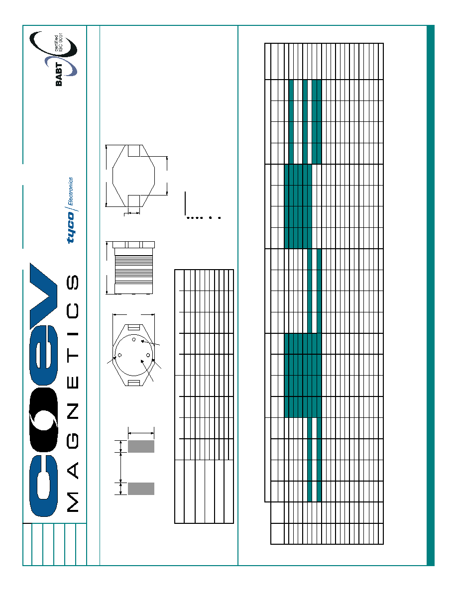
SMD Unshielded Power Inductor Series; Part Numbering Sequence: ( Series Number ) - ( Suffix Code )(Tolerance), example DU1330-220M
Bulk Packaging add (-B) to end of Part Numbering Sequence. example DU1330-220M-B
Series
Number
Units
L
W
H
Y
Z
A
B
C
inches
0.260"
0.177"
0.115"
0.190"
0.050"
0.140"
0.055"
0.160"
[ mm ]
[ 6.60 ]
[ 4.50 ]
[ 2.92 ]
[ 4.83 ]
[ 1.27 ]
[ 3.56 ]
[ 1.40 ]
[ 4.06 ]
inches
0.510"
0.370"
0.130"
0.300"
0.100"
0.110"
0.115"
0.290"
[ mm ]
[ 12.95 ]
[ 9.40 ]
[ 3.30 ]
[ 7.62 ]
[ 2.54 ]
[ 2.79 ]
[ 2.92 ]
[ 7.37 ]
inches
0.510"
0.370"
0.205"
0.300"
0.100"
0.110"
0.115"
0.290"
[ mm ]
[ 12.95 ]
[ 9.40 ]
[ 5.21 ]
[ 7.62 ]
[ 2.54 ]
[ 2.79 ]
[ 2.92 ]
[ 7.37 ]
inches
0.510"
0.370"
0.450"
0.300"
0.100"
0.110"
0.115"
0.290"
[ mm ]
[ 12.95 ]
[ 9.40 ]
[ 11.43 ]
[ 7.62 ]
[ 2.54 ]
[ 2.79 ]
[ 2.92 ]
[ 7.37 ]
inches
0.730"
0.600"
0.291"
0.500"
0.100"
0.110"
0.115"
0.490"
[ mm ]
[ 18.54 ]
[ 15.24 ]
[ 7.40 ]
[ 12.70 ]
[ 2.54 ]
[ 2.79 ]
[ 2.92 ]
[ 12.45 ]
DU6629
DU1330
DU1352
DU1311
DU1971
L
1
Suffix
DCR
2
I
SAT
3
I
RMS
5
Tolerance
DCR
2
I
SAT
3
I
RMS
5
Tolerance
DCR
2
I
SAT
3
I
RMS
6
Tolerance
DCR
2
I
SAT
3
I
RMS
7
Tolerance
DCR
2
I
SAT
3
I
RMS
7
Tolerance
µH
Codes
A
A
Suffix
4
A
A
Suffix
4
A
A
Suffix
4
A
A
Suffix
4
A
A
Suffix
4
1.0
1R0
0.050
2.90
2.90
M
0.0092
9.00
6.80
M
0.009
20.00
8.60
M
1.5
1R5
0.050
2.60
2.80
M
0.0104
8.00
6.40
M
BRN GRN RED
2.2
2R2
0.070
2.30
2.40
M
0.0120
7.00
6.10
M
0.014
16.00
7.10
M
RED RED RED
3.3
3R3
0.080
2.00
2.00
M
0.0150
6.40
5.40
M
0.018
14.00
6.20
M
ORG ORG RED
4.7
4R7
0.090
1.50
1.50
M
0.0184
5.40
4.80
M
YEL VIO RED
5.6
5R6
0.020
12.00
5.30
M
GRN BLU RED
6.8
6R8
0.130
1.20
1.40
M
0.0270
4.60
4.40
M
0.015
10.00
5.00
M
BLU GRY RED
8.0
8R0
0.022
9.50
4.00
M
GRY BLK RED
10
100
0.160
1.10
1.30
M
0.110
2.40
2.00
M
0.0380
3.80
3.90
M
0.040
8.00
3.50
M
0.031
10.00
4.30
M
BRN BLK ORG
15
150
0.230
0.90
1.20
M
0.150
2.00
1.50
M
0.0460
3.00
3.10
M
0.050
7.00
3.00
M
0.036
8.00
4.00
M
BRN GRN ORG
22
220
0.370
0.70
0.80
M
0.230
1.60
1.30
M
0.0850
2.60
2.70
M
0.070
5.50
2.50
M
0.047
7.00
3.50
M
RED RED ORG
33
330
0.510
0.58
0.60
M
0.300
1.40
1.10
M
0.1012
2.00
2.10
M
0.080
4.00
2.00
M
0.066
5.50
3.00
M
ORG ORG ORG
47
470
0.640
0.50
0.50
M
0.390
1.00
0.80
M
0.1400
1.60
1.80
M
0.110
3.80
1.60
M
0.086
4.50
2.60
M
YEL VIO ORG
68
680
0.860
0.40
0.40
M
0.660
0.90
0.70
M
0.2000
1.40
1.50
M
0.170
3.00
1.20
M
0.130
3.50
2.30
M
BLU GRY ORG
100
101
1.270
0.31
0.30
M
0.840
0.70
0.60
M
0.2800
1.20
1.30
M
0.220
2.50
1.20
M
0.190
3.00
1.80
M
BRN BLK YEL
150
151
2.000
0.27
0.25
M
1.200
0.60
0.50
M
0.4000
1.00
1.00
M
0.340
2.00
0.90
M
0.250
2.60
1.50
M
BRN GRN YEL
220
221
3.110
0.22
0.20
M
1.900
0.50
0.40
M
0.6100
0.80
0.80
M
0.440
1.60
0.70
M
0.380
2.40
1.20
M
RED RED YEL
330
331
4.800
0.18
0.16
M
2.700
0.40
0.30
M
1.0200
0.60
0.60
M
0.700
1.20
0.60
M
0.560
1.90
1.00
M
ORG ORG YEL
470
471
6.600
0.16
0.15
M
4.000
0.30
0.20
M
1.2700
0.50
0.50
M
0.950
1.00
0.30
M
0.850
1.40
0.82
M
YEL VIO YEL
680
681
9.200
0.10
0.12
M
5.300
0.20
0.10
M
2.0200
0.40
0.40
M
1.200
1.00
0.20
M
1.100
1.20
0.72
M
BLU GRY YEL
1000
102
13.800
0.10
0.07
M
8.400
0.10
0.05
M
3.0000
0.30
0.30
M
2.000
0.80
0.10
M
1.800
1.00
0.56
M
BRN BLK GRN
1) Tested at 100kHz, 100mVrms @20∞C
6) Current applied to produce a typical 15∞C temperature rise from nominal inductance.
2) DCRs (DC resistances) are maximums @20∞C.
7) Current applied to produce a typical 40∞C temperature rise from nominal inductance.
3) DC (Direct Current) current applied to produce a typical 10% drop in inductance.
4) Suffix of M=20%
5) Current applied to produce a typical 30∞C temperature rise from nominal inductance.
Call Toll Free: 888-978-2638 Website: www.tycopowercomponents.com
Maximum Dimensions
Nominal Dimensions
DU6629
DU1330
Dot Code
1st 2nd 3rd
BRN BLK RED
DU1352
DU1311
DU1971
Significant Digit
H
Y
W
L
Z
Suffix Code
XXX
1st significant digit
3rd significant digit
2nd significant digit
Parts will be marked with Significant Digit Dots OR Suffix code
B
A
C
B
Suggested Land Pattern
Features:
High enerty storage and low resistance
Ideal for DC-DC step-up or step-down conversion
Reliable surface mounting, flat top for pick and place
Robust temperature deflection to provent damage
during solder reflow
Drop in replacements for industry prevalent
competitor series
Operating temperature -40∞C to +85∞C
Specifications subject to change without notice.
Item
Specification
Test Method/Condition
Environmental
Static Humidity
After exposure part remains within
specified electrical parameters for
L, Q and DCR.
Storage Life
After exposure part remains within
specified electrical parameters for
L, Q and DCR.
Moisture Resistance
After exposure, part shall not
Per MIL-STD 202 Method 106, ten 24 hour cycles at +25∞C to
have a shorted or open winding.
+65∞C at 80 to 95% R.H. During any of the first 9 cycles, inductors
are revolved from the chamber and exposed to -10∞C for 3 hours.
Allow parts to dry for 2 hours before measurements are taken.
Temperature Cycle
After exposure part remains
10 cycles (Air to Air) 1 cycle shall consist of:
within specified electrical
30 minutes exposure to +85∞C
parameters for L, Q and DCR.
30 minutes exposure to -40∞C
Allow 20 minutes transition between extremes.
Temperature Shock
After exposure part remains
10 cycles (Air to Air) 1 cycle shall consist of:
within specified electrical
30 minutes exposure to -45∞C
parameters for L, Q and DCR.
30 minutes exposure to +125∞C
15 seconds maximum transition between temperatures
General
Storage Temperature
Range
-40∞C to +85∞C
Operating Temperature
Range
-40∞C to +85∞C
Flammability
IEC 695-2-2
Withstands needle-flame test
Other
Vibration
After exposure part remains
Inductors shall be randomly vibrated per NAVMAT P9492
within specified electrical
profile. Samples shall be subjected to 0.04G/Hz for a
parameters for L, Q and DCR.
minimum of 15 minutes per axis, for each of the three axes.
Mechanical Shock
After exposure part remains
Test per MIL-STD 202 method 213 test condition A, test
within specified electrical
mounted samples 3 axes, 6 times, totaling 18 shocks.
parameters for L, Q and DCR.
(50Gs, 11ms, half-sine).
Solderability
Wetting shall cover 90% minimum
of each termination
Component Adhesion
(Push Test)
4 pounds
Apply and measure force with a digital force gauge set.
Resistance to Solvent
No sign of degradation in
Withstands 6 minutes of alcohol.
appearance or marking detail.
Withstands 3 minutes forced spray Freon TMS
Load Life
After exposure, part shall not
Parts to be stored at 110∞C for 1000 hours with rated current
have a shorted or open winding.
applied. Parts to be tested at: start, 500 and 1000 hours. Allow
2 hours at room temperature before testing.
Series
Revision
Sheet 3 of 3
Subject parts to an environment of +50∞C 90 to 100% R.H. for 46 to 50
hours. After exposure, allow parts to dry for 2 hours before measurements
are taken.
Expose parts to an environment of +50∞C with 90 to 95% R.H. for 100
hours. After exposure, allow parts to dry for 2 hours before measurements
are taken.
DU SERIES
C
For Print Distribution to Customers
Dip pads in RMA flux, 63/37 solder (Sn/Pb) at 232∞C for 5 seconds ±2
seconds.
