Surface Mount
Abrupt Tuning Varactors
MA45430 Series
M/A-COM, Inc.
North America:
Tel. (800) 366-2266
s
Asia/Pacific: Tel. +81 3 3263 8761
s
Europe: Tel. +44 (1344) 869 595
Fax (800) 618-8883
Fax +81 3 3263 8769
Fax +44 (1344) 300 020
1
Specifications Subject to Change Without Notice.
V3.00
Features
q
Surface Mount Package
q
Low Cost
q
High Quality Factor
q
Tape and Reel Packaging Available
q
SPC Controlled Process for Superior C-V Repeatability
q
Available as Singles and Common Cathode Pairs
Description
The MA45430 series are abrupt junction silicon tuning
varactors in the SOT-23 surface mount package. These
thermal oxide passivated diodes feature high capacitance
ratio and quality factor. They are well suited for tuning in
the HF to UHF frequency bands. The standard capaci-
tance tolerance is ±10%, with tighter tolerances available.
Capacitance matching at one or more bias voltages is
also available.
Applications
The MA45430 series tuning varactor is useful for tuning
applications in the HF through UHF ranges. Applications
include VCOs and voltage tuned filters in radios, cable
TV tuners and test instruments where low cost and excel-
lent lot-to-lot repeatability are critical.
Ordering Information
The part numbers shown are for single diodes. When
ordering diodes in common cathode pairs add suffix
"CK." For example, MA45436CK specifies model number
MA45436 as a common cathode pair. To order parts on
tape and reel add suffix T/R to the end of the part num-
ber. i.e. MA45436CK - T/R.
Mounting Information
The diagram below indicates the recommended mount-
ing pad configuration for the SOT-23 package. Solder
paste containing flux should be screened onto the pads
to a thickness of 0.005 inches. The SOT-23 device is
placed in position, firmly adhering to the solder paste.
Permanent attachment is performed by a reflow soldering
procedure. The tab temperature must not exceed 275∞C
and the body temperature must not exceed 250∞C.
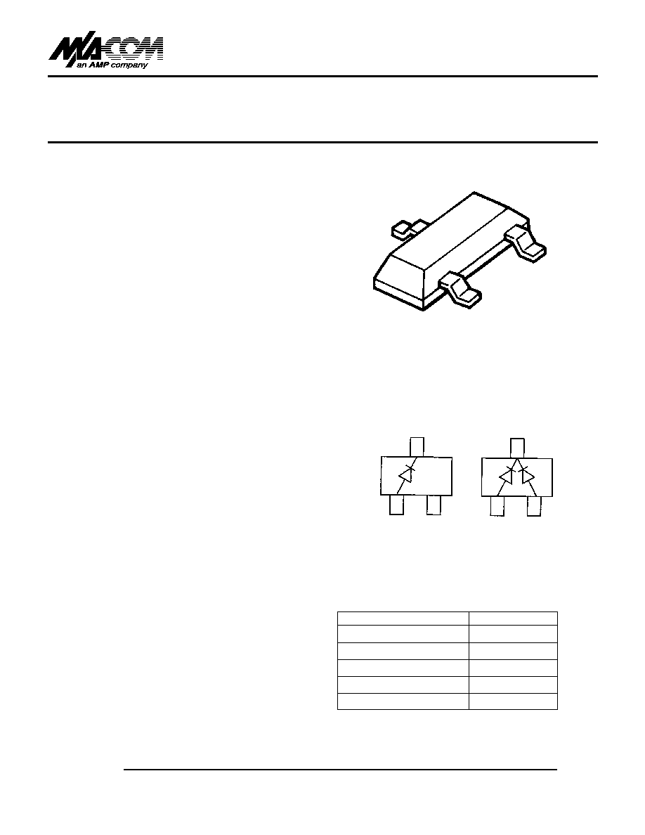
SOT-23
Configurations
TOP VIEW
(SINGLE)
(COMMON CATHODE PAIR)
Absolute Maximum Ratings at 25∞C
Note:
1. At 25
∞
C case temperature. Derate linearly to 0 mW at 150
∞
C.
Parameter
Absolute Maximum
Reverse Voltage
30 V
Forward Current
50 mA
Total Power Dissipation
1
250 mW
Junction Operating Temperature
-55∞C to +150∞C
Storage Temperature
-55∞C to +150∞C

Surface Mount Abrupt Tuning Varactors
MA45430 Series
V3.00
M/A-COM, Inc.
North America:
Tel. (800) 366-2266
s
Asia/Pacific: Tel. +81 3 3263 8761
s
Europe: Tel. +44 (1344) 869 595
Fax (800) 618-8883
Fax +81 3 3263 8769
Fax +44 (1344) 300 020
2
Specifications Subject to Change Without Notice.
Electrical Specifications
@ 25∞C
Minimum Breakdown Voltage (V
B
) = 30 Volts at 10µA
Maximum Reverse Current (I
R
) = 100 nA at 24 Volts
Lower capacitance values available upon request
* Available as single diodes only.
Total
Capacitance
Minimum
Model
C
T4
± 10%
Capacitance Ratio
Minimum
Number
(pF)
C
T0
/C
T30
Q
MA45436
4.7
4.5
1800
MA45437
5.6
4.5
1700
MA45438
6.8
4.5
1600
MA45439
8.2
4.5
1500
MA45440
10.0
4.5
1300
MA45441
12.0
4.6
1200
MA45444*
22.0
4.6
1000
MA45445*
27.0
4.7
900
MA45446*
33.0
4.7
750
MA45448*
47.0
4.7
400
Test
V
R
= 4 V
V
R
= 0/30 V
V
R
= 4 V
Conditions
f = 1 MHz
f = 1 MHz
f = 50 MHz
Typical Performance Curve
MA46H070≠MA46H073
Reverse Voltage (Volts)
Capacitance vs. Reverse Voltage
0.1
1
10
100
100
10
1
Total Capacitance (pF)
MA45448
MA45446
MA45444
MA45440
MA45438
MA45436
CAPACITANCE vs REVERSE VOLTAGE
Case Style
SOT-23 (High Profile)
Note:
1. Applicable on all sides
INCHES
MILLIMETERS
DIM.
MIN.
MAX.
MIN.
MAX.
A
--
0.048
--
1.22
B
--
0.008
--
0.20
C
--
0.040
--
1.00
D
0.013
0.020
0.35
0.50
E
0.003
0.006
0.08
0.15
F
0.110
0.119
2.80
3.00
G
0.047
0.056
1.20
1.40
H
0.037 typical
0.95 typical
J
0.075 typical
1.90 typical
K
0.103
2.60
L
0.024
0.60
DIM.
GRADIENT
M
10∞ max.
1
N
2∞...30∫
DIMENSIONS MILLIMETERS (INCHES)