
GaAs SPST High Isolation Terminated
Switch, 0.5 - 2.0 GHz
SW
-393
SOIC-8
V 3.00
Features
!
Terminated RF Output
!
High Isolation: 42 dB up to 2 GHz
!
Single Positive Control
!
CMOS Compatible Logic
!
Low Cost SOIC 8 Plastic Package
Description
M/A-COM's SW-393 is a GaAs monolithic SPST
terminated switch in a low cost SOIC 8-lead plastic
package. The SW-393 is ideally suited for use where low
power consumption and high isolation are required.
Typical applications include PCS and GSM LO Switching,
switch matrices and switched filter banks in systems such as
radio and cellular equipment.
The SW-393 is fabricated using a mature 1-micron gate
length GaAs MESFET process. The process features full
chip passivation for increased performance and reliability.
Electrical Specifications
1
: T
A
= 25�C
Parameter
Test Conditions
Frequency
Units
Min
Typ
Max
Insertion Loss
0.5 - 2.0 GHz
dB
--
1.6
1.8
Isolation
0.5 - 1.0 GHz
1.0 - 2.0 GHz
dB
dB
50
40
53
42
--
--
VSWR
0.5 - 1.5 GHz
0.5 - 2.0 GHz
Ratio
Ratio
--
--
1.5:1
1.7:1
--
--
1 dB Compression
Input Power, +5V Control/Supply
0.5 GHz
0.9 GHz
1.5 GHz
dBm
dBm
dBm
--
--
--
25
25
26
--
--
--
Trise, Tfall
10% to 90% RF, 90% to 10% RF
�s
--
2
--
Ton, Toff
50% Control to 90% RF,
Control to 10% RF
�s
--
2
--
Transients
In-Band
mV
--
26
--
Input IP
2
2-Tone, 5 MHz spacing,
+10 dBm each
0.5 GHz
0.9 GHz
dBm
dBm
--
--
53
58
--
--
Input IP
3
2-Tone, 5 MHz spacing,
+10 dBm each
0.5 GHz
0.9 GHz
dBm
dBm
--
--
39
38
--
--
1. All measurements taken at 900 MHz in a 50 Ohm system unless otherwise specified. Loss varies at 0.003 dB/�C.

GaAs SPST High Isolation Terminated Switch, 0.5 - 2.0 GHz
SW-393
V 3.00
M/A-COM Inc. and its affiliates reserve the right to make changes to the product(s)
or information contained herein without notice.
Visit www.macom.com for additional data sheets and product information.
!
North America: Tel. (800) 366-2266
!
Asia/Pacific: Tel.+81-44-844-8296, Fax +81-44-844-8298
!
Europe: Tel. +44 (1344) 869 595, Fax+44 (1344) 300 020
2
Functional Schematic
Pin Configuration
Pin No.
Function
Pin No.
Function
1
GND
5
GND
2
RF1
6
CTL
3
GND
7
RF2
4
GND
8
GND
Absolute Maximum Ratings
2
2. Operation of this device above any one of these
parameters may cause permanent damage.
Parameter
Absolute Maximum
Input Power
+34 dBm
Operating Voltage (V
S
, V
CTL
)
+8.5 Volts
Operating Temperature
-40�C to +85�C
Storage Temperature
-65�C to +150�C
Truth Table
Control
RF1 - RF2
0
Off
1
On
"0" = 0 � 0.2 VDC, "1" = +5 � 0.2 VDC, Vs = +5 � 0.2 VDC
Blocking capacitors are required on all RF ports. V
S
can be
applied at RF1 or RF2 using 10K or greater pull-up resistors.
8
7
6
5
1
2
3
4
V
S
10k
50
Ohms
GaAs SPST High Isolation Terminated Switch, 0.5 - 2.0 GHz
SW-393
V 3.00
M/A-COM Inc. and its affiliates reserve the right to make changes to the product(s)
or information contained herein without notice.
Visit www.macom.com for additional data sheets and product information.
!
North America: Tel. (800) 366-2266
!
Asia/Pacific: Tel.+81-44-844-8296, Fax +81-44-844-8298
!
Europe: Tel. +44 (1344) 869 595, Fax+44 (1344) 300 020
3
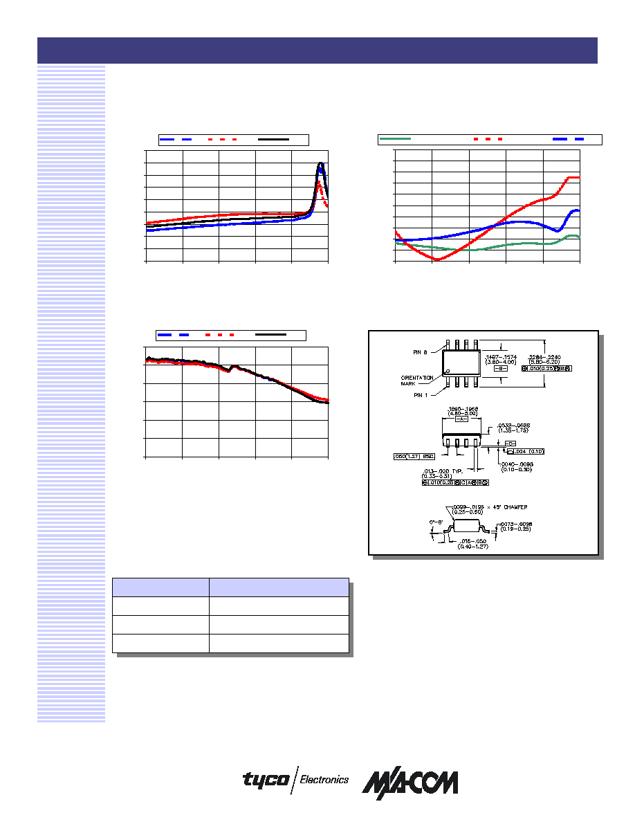
Typical Performance Curves
VSWR vs. Frequency
Insertion Loss vs. Frequency
Isolation vs. Frequency
Ordering Information
Part Number
Package
SW-393 PIN
SOIC 8-Lead Plastic Package
SW-393TR
Tape and Reel
3
SW-393SMB
Sample Board
3. Refer to Application Note M513 for reel size information.
OUTLINE DRAWING
0
0.5
1
1.5
2
2.5
3
3.5
4
4.5
0.5
1
1.5
2
2.5
3
Frequency (GHz)
IL (dB)
-40C
+85C
+25C
1
1.2
1.4
1.6
1.8
2
2.2
2.4
2.6
2.8
3
0.5
1
1.5
2
2.5
3
Frequency (GHz)
VSWR
Output Insertion Loss
Output Isolation
Input
0
10
20
30
40
50
60
0.5
1
1.5
2
2.5
3
Frequency (GHz)
ISOL (dB)
-40C
+85C
+25C