 | –≠–ª–µ–∫—Ç—Ä–æ–Ω–Ω—ã–π –∫–æ–º–ø–æ–Ω–µ–Ω—Ç: SW-461 | –°–∫–∞—á–∞—Ç—å:  PDF PDF  ZIP ZIP |

V2.00
Features
∑
High Isolation: 40 dB
∑
Low Current draw: < 2mA @ +5 V
< 10mA @ -5V
∑
5V CMOS Logic
∑
45mm PBGA Package
∑
JEDEC MO-151 Foot Print
PBGA Package Outline
Electrical Specifications: T
A
= +25∞C
1
, Control Voltage = +5.0V
=
=
=
=
4x6 RF Switch Matrix
4x6 RF Switch Matrix
4x6 RF Switch Matrix
4x6 RF Switch Matrix
800
800
800
800 ---- 900 MHz
900 MHz
900 MHz
900 MHz
SW-461
Description
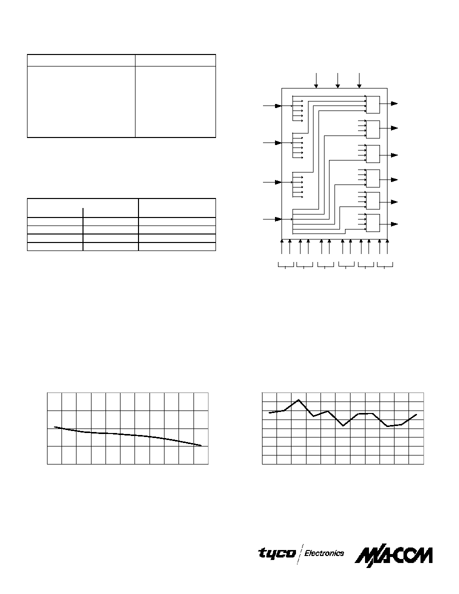
M/A-COM's SW-461 is a multi-chip module containing six
SP4T GaAs switches, each with a driver/decoder and four
GaAs 6-way power dividers. The SW-461 utilizes Plastic Ball
Grid Array (PBGA) interconnect technology to achieve high
circuit density and superior high frequency performance. This
device is ideal for telephony applications in the AMPS
frequency bands.
The SW-461 is constructed with a multi layer PCB using a ball
grid array for the I/O connects. The combination of several
state-of-the-art technologies achieves high performance at a low
cost.
Ordering Information
Part Number
Package
SW-461
45mm PBGA Package
Parameter
Test Conditions
Units
Min.
Typ.
Max.
Insertion Loss
800 - 900 MHz
dB
-11.5
-12
VSWR
800 - 900 MHz
1.5:1
1.9:1
Isolation
800 - 900 MHz
dB
42
57
Balance
800 - 900 MHz
dB
0.7
1.2
P
1dB
800 - 900 MHz
dBm
33
1. All measurements in a 50
system.
North America: Tel. (800) 366-2266, Fax (800) 618-8883
Asia/Pacific: Tel.+81-44-844-8296, Fax +81-44-844-8298
Europe: Tel. +44 (1344) 869 595, Fax+44 (1344) 300 020
Specifications subject to change without notice.
Visit www.macom.com for additional data sheets and product information.
V 2.0
V2.00
50
55
60
65
70
75
80
85
90
0.8
0.81
0.82
0.83
0.84
0.85
0.86
0.87
0.88
0.89
0.9
FREQUENCY (MHz)
dB
20
25
30
35
40
0.8
0.81
0.82
0.83
0.84
0.85
0.86
0.87
0.88
0.89
0.9
FREQUENCY (MHz)
dB
Typical Performance Curves
Parameter
Absolute Maximum
Maximum Voltage
-5V, 5V
Maximum Current
-10 mA, 20 mA
Maximum Disspated Power
150 mW
Total Maximum Input Power
36 dBm
Storage Temperature
-65∞C to +150∞C
Operating Temperature
0∞ to 65∞C
Absolute Maximum Ratings
1
1. Exceeding any one or a combination of these limits may cause
permanent damage.
Power Divider Isolation
Output to Output Isolation
Selected
A
B
Input
0
0
1
1
0
2
0
1
3
1
1
4
Output
n
Control Pair
3
Truth Table
1,2
1. "0" = 0±0.2V
2. "1" = 5±0.2V
3. n = SP4T 1 through 6
SP4T
3
SP4T
2
SP4T
1
SP4T
4
SP4T
5
SP4T
6
OUT 4
OUT 3
OUT 2
OUT 1
OUT 5
OUT 6
IN 4
IN 3
IN 2
IN 1
Switch Control Pairs
2A 2B 3A 3B 4A 4B 5A 5B 6A 6B
+5V
GND
-5V
SP4T
SP4T
SP4T
SP4T
SP4T
SP4T
1A 1B
Functional Schematic
V 2.0
North America: Tel. (800) 366-2266, Fax (800) 618-8883
Asia/Pacific: Tel.+81-44-844-8296, Fax +81-44-844-8298
Europe: Tel. +44 (1344) 869 595, Fax+44 (1344) 300 020
Specifications subject to change without notice.
Visit www.macom.com for additional data sheets and product information.

V2.00
50
60
70
80
90
100
0.8
0.81
0.82
0.83
0.84
0.85
0.86
0.87
0.88
0.89
0.9
FREQUENCY (MHz)
ISOL
AT
ION d
B
10
10.2
10.4
10.6
10.8
11
11.2
11.4
11.6
11.8
12
0.8
0.81
0.82
0.83
0.84
0.85
0.86
0.87
0.88
0.89
0.9
FREQUENCY (MHz)
INSERT
I
ON L
O
SS d
B
0
2
4
6
8
10
12
14
16
18
20
0.8
0.81
0.82
0.83
0.84
0.85
0.86
0.87
0.88
0.89
0.9
FREQUENCY (MHz)
RET
URN L
O
SS d
B
14.5
14.6
14.7
14.8
14.9
15
15.1
15.2
15.3
15.4
15.5
0.8
0.81
0.82
0.83
0.84
0.85
0.86
0.87
0.88
0.89
0.9
FREQUENCY (MHz)
RE
TURN L
O
S
S
d
B
-70
-60
-50
-40
-30
-20
0.80
0.81
0.82
0.83
0.84
0.85
0.86
0.87
0.88
0.89
0.90
FREQUENCY (MHz)
ISOL
AT
ION d
B
c
Typical Performance Curves (Cont'd)
Input Return Loss vs. Frequency
Insertion Loss vs. Frequency
Adjacent Input Isolation
On/Off Switch Isolation
Output Return Loss vs. Frequency
North America: Tel. (800) 366-2266, Fax (800) 618-8883
Asia/Pacific: Tel.+81-44-844-8296, Fax +81-44-844-8298
Europe: Tel. +44 (1344) 869 595, Fax+44 (1344) 300 020
Specifications subject to change without notice.
Visit www.macom.com for additional data sheets and product information.
V 2.0