 | –≠–ª–µ–∫—Ç—Ä–æ–Ω–Ω—ã–π –∫–æ–º–ø–æ–Ω–µ–Ω—Ç: MAX1619 | –°–∫–∞—á–∞—Ç—å:  PDF PDF  ZIP ZIP |
________________General Description
The MAX1619 is a precise digital thermometer that reports
the temperature of both a remote sensor and its own
package. The remote sensor is a diode-connected transis-
tor--typically a low-cost, easily mounted 2N3904 NPN
type--that replaces conventional thermistors or thermo-
couples. Remote accuracy is ±3∞C for multiple transistor
manufacturers, with no calibration needed. The remote
channel can also measure the die temperature of other
ICs, such as microprocessors, that contain an on-chip,
diode-connected transistor.
The 2-wire serial interface accepts standard System
Management Bus (SMBus
Æ
) Write Byte, Read Byte, Send
Byte, and Receive Byte commands to program the alarm
thresholds and to read temperature data. The data format
is 7 bits plus sign, with each bit corresponding to 1∞C, in
two's complement format. Measurements can be done
automatically and autonomously, with the conversion rate
programmed by the user or programmed to operate in a
single-shot mode. The adjustable rate allows the user to
control the supply-current drain.
The MAX1619 is nearly identical to the popular MAX1617A,
with the additional feature of an overtemperature alarm out-
put (OVERT) that responds to the remote temperature; this
is optimal for fan control.
________________________Applications
Desktop and Notebook
Central Office
Computers
Telecom Equipment
Smart Battery Packs
Test and Measurement
LAN Servers
Multichip Modules
Industrial Controls
____________________________Features
o
Two Channels Measure Both Remote and Local
Temperatures
o
No Calibration Required
o
SMBus 2-Wire Serial Interface
o
Programmable Under/Overtemperature Alarms
o
OVERT
Output for Fan Control
o
Supports SMBus Alert Response
o
Supports Manufacturer and Device ID Codes
o
Accuracy
±2∞C (+60∞C to +100∞C, local)
±3∞C (-40∞C to +125∞C, local)
±3∞C (+60∞C to +100∞C, remote)
o
3µA (typ) Standby Supply Current
o
70µA (max) Supply Current in Auto-Convert Mode
o
+3V to +5.5V Supply Range
o
Write-Once Protection
o
Small 16-Pin QSOP Package
MAX1619
Remote/Local Temperature Sensor with Dual-
Alarm Outputs and SMBus Serial Interface
________________________________________________________________
Maxim Integrated Products
1
MAX1619
SMBCLK
ADD0 ADD1
V
CC
STBY
GND
ALERT
SMBDATA
DXP
DXN
INTERRUPT
TO
µ
C
FAN
CONTROL
+3V TO +5.5V
200
0.1
µ
F
CLOCK
10k EACH
DATA
2N3904
2200pF
OVERT
___________________Pin Configuration
16
15
14
13
12
11
10
9
1
2
3
4
5
6
7
8
V
CC
N.C.
STBY
SMBCLK
N.C.
SMBDATA
ALERT
ADD0
OVERT
TOP VIEW
MAX1619
QSOP
GND
DXP
ADD1
DXN
N.C.
GND
GND
Typical Operating Circuit
19-1483; Rev 0; 4/99
PART
MAX1619MEE
-55∞C to +125∞C
TEMP. RANGE
PIN-PACKAGE
16 QSOP
Ordering Information
SMBus is a registered trademark of Intel Corp.
For free samples & the latest literature: http://www.maxim-ic.com, or phone 1-800-998-8800.
For small orders, phone 1-800-835-8769.

MAX1619
Remote/Local Temperature Sensor with Dual-
Alarm Outputs and SMBus Serial Interface
2
_______________________________________________________________________________________
ABSOLUTE MAXIMUM RATINGS
ELECTRICAL CHARACTERISTICS
(V
CC
= +3.3V,
T
A
= 0∞C to +85∞C
, configuration byte = XCh, unless otherwise noted.)
Stresses beyond those listed under "Absolute Maximum Ratings" may cause permanent damage to the device. These are stress ratings only, and functional
operation of the device at these or any other conditions beyond those indicated in the operational sections of the specifications is not implied. Exposure to
absolute maximum rating conditions for extended periods may affect device reliability.
V
CC
to GND ..............................................................-0.3V to +6V
DXP, ADD_ to GND ....................................-0.3V to (V
CC
+ 0.3V)
DXN to GND ..........................................................-0.3V to +0.8V
SMBCLK, SMBDATA, ALERT, OVERT,
STBY to GND............................................................-0.3V to +6V
SMBDATA, ALERT, OVERT Current....................-1mA to +50mA
DXN Current .......................................................................±1mA
ESD Protection (all pins, Human Body Model) ..................2000V
Continuous Power Dissipation (T
A
= +70∞C)
QSOP (derate 8.30mW/∞C above +70∞C) .....................667mW
Operating Temperature Range .........................-55∞C to +125∞C
Junction Temperature ......................................................+150∞C
Storage Temperature Range .............................-65∞C to +150∞C
Lead Temperature (soldering, 10sec) .............................+300∞C
T
A
= +60∞C to +100∞C
Monotonicity guaranteed
ADD0, ADD1; momentary upon power-on reset
DXP forced to 1.5V
Logic inputs
forced to V
CC
or GND
Auto-convert mode
From stop bit to conversion complete (both channels)
V
CC
, falling edge
T
A
= 0∞C to +85∞C
V
CC
input, disables A/D conversion, rising edge
Autoconvert mode, average
measured over 4sec. Logic
inputs forced to V
CC
or GND.
CONDITIONS
µA
160
Address Pin Bias Current
V
0.7
DXN Source Voltage
µA
8
10
12
80
100
120
Remote-Diode Source Current
%
-25
25
Conversion Rate Timing Error
ms
94
125
156
Conversion Time
µA
120
180
35
70
Average Operating Supply Current
-2
2
Bits
8
Temperature Resolution (Note 1)
µA
5
Standby Supply Current
3
10
mV
50
POR Threshold Hysteresis
V
1.0
1.7
2.5
Power-On Reset Threshold
∞C
-3
3
Initial Temperature Error,
Local Diode (Note 2)
V
3.0
5.5
Supply Voltage Range
V
2.60
2.80
2.95
Undervoltage Lockout Threshold
mV
50
Undervoltage Lockout Hysteresis
UNITS
MIN
TYP
MAX
PARAMETER
T
R
= +60∞C to +100∞C
T
R
= -55∞C to +125∞C (Note 4)
-3
3
∞C
-5
5
Temperature Error, Remote Diode
(Notes 2, 3)
Including long-term drift
-2.5
2.5
∞C
-3.5
3.5
Temperature Error, Local Diode
(Notes 1, 2)
0.25 conv/sec
2.0 conv/sec
T
A
= +60∞C to +100∞C
T
A
= 0∞C to +85∞C
High level
Low level
ADC AND POWER SUPPLY
SMBus static
Hardware or software standby,
SMBCLK at 10kHz

MAX1619
Remote/Local Temperature Sensor with Dual-
Alarm Outputs and SMBus Serial Interface
_______________________________________________________________________________________
3
ELECTRICAL CHARACTERISTICS (continued)
(V
CC
= +3.3V,
T
A
= 0∞C to +85∞C
, configuration byte = XCh, unless otherwise noted.)
STBY, SMBCLK, SMBDATA; V
CC
= 3V to 5.5V
t
HIGH
, 90% to 90% points
t
LOW
, 10% to 10% points
(Note 5)
SMBCLK, SMBDATA
Logic inputs forced to V
CC
or GND
ALERT, OVERT, forced to 5.5V
STBY, SMBCLK, SMBDATA; V
CC
= 3V to 5.5V
ALERT, OVERT, SMBDATA forced to 0.4V
CONDITIONS
µs
4
SMBCLK Clock High Time
µs
4.7
SMBCLK Clock Low Time
kHz
DC
100
SMBus Clock Frequency
pF
5
SMBus Input Capacitance
µA
-1
1
Logic Input Current
µA
1
ALERT, OVERT Output High
Leakage Current
V
2.2
Logic Input High Voltage
V
0.8
Logic Input Low Voltage
mA
6
Logic Output Low Sink Current
UNITS
MIN
TYP
MAX
PARAMETER
t
SU:DAT
, 10% or 90% of SMBDATA to 10% of SMBCLK
t
SU:STO
, 90% of SMBCLK to 10% of SMBDATA
t
HD:STA
, 10% of SMBDATA to 90% of SMBCLK
t
SU:STA
, 90% to 90% points
ns
250
SMBus Data Valid to SMBCLK
Rising-Edge Time
µs
4
SMBus Stop-Condition Setup Time
µs
4
SMBus Start-Condition Hold Time
ns
500
SMBus Repeated Start-Condition
Setup Time
µs
4.7
SMBus Start-Condition Setup Time
t
HD:DAT
(Note 6)
µs
0
SMBus Data-Hold Time
Master clocking in data
µs
1
SMBCLK Falling Edge to SMBus
Data-Valid Time
SMBus INTERFACE
ELECTRICAL CHARACTERISTICS
(V
CC
= +3.3V,
T
A
= -55∞C to +125∞C
, configuration byte = XCh, unless otherwise noted.) (Note 4)
CONDITIONS
Monotonicity guaranteed
T
A
= +60∞C to +100∞C
Bits
8
Temperature Resolution (Note 1)
-2
2
T
R
= +60∞C to +100∞C
T
A
= -55∞C to +125∞C
∞C
-3
3
Initial Temperature Error,
Local Diode (Note 2)
V
3.0
5.5
Supply Voltage Range
From stop bit to conversion complete (both channels)
Autoconvert mode
ms
94
125
156
Conversion Time
%
-25
25
Conversion Rate Timing Error
-3
3
T
R
= -55∞C to +125∞C
∞C
UNITS
MIN
TYP
MAX
-5
5
PARAMETER
Temperature Error, Remote Diode
(Notes 2, 3)
ADC AND POWER SUPPLY
0
6
3
9
12
50
5k
500k
50k
5M
500
50M
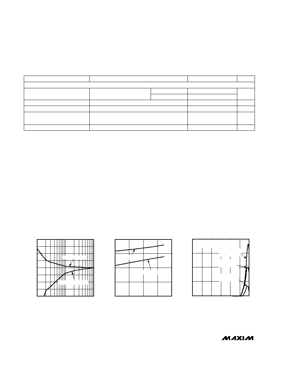
TEMPERATURE ERROR vs.
POWER-SUPPLY NOISE FREQUENCY
MAX1619-03
FREQUENCY (Hz)
TEMPERATURE ERROR (∞C)
V
IN
= SQUARE WAVE APPLIED TO
V
CC
WITH NO 0.1
µ
F V
CC
CAPACITOR
V
IN
= 250mVp-p
REMOTE DIODE
V
IN
= 100mVp-p
LOCAL DIODE
V
IN
= 100mVp-p
REMOTE DIODE
-20
-10
-15
0
-5
10
5
20
15
TEMPERATURE ERROR
vs. PC BOARD RESISTANCE
MAX1619-01
LEAKAGE RESISTANCE (M
)
TEMPERATURE ERROR (∞C)
1
10
100
PATH = DXP TO GND
PATH = DXP TO V
CC
(5V)
-2
-1
0
1
2
-50
50
100
0
150
TEMPERATURE ERROR
vs. REMOTE-DIODE TEMPERATURE
MAX1619-02
TEMPERATURE (∞C)
TEMPERATURE ERROR (∞C)
MOTOROLA MMBT3904
ZETEX FMMT3904
RANDOM
SAMPLES
__________________________________________Typical Operating Characteristics
(T
A
= +25∞C, unless otherwise noted.)
MAX1619
Remote/Local Temperature Sensor with Dual-
Alarm Outputs and SMBus Serial Interface
4
_______________________________________________________________________________________
ELECTRICAL CHARACTERISTICS (continued)
(V
CC
= +3.3V,
T
A
= -55∞C to +125∞C
, configuration byte = XCh, unless otherwise noted.) (Note 4)
Note 1:
Guaranteed but not 100% tested.
Note 2:
Quantization error is not included in specifications for temperature accuracy. For example, if the MAX1619 device tempera-
ture is exactly +66.7∞C, the ADC may report +66∞C, +67∞C, or +68∞C (due to the quantization error plus the +1/2∞C offset
used for rounding up) and still be within the guaranteed ±1∞C error limits for the +60∞C to +100∞C temperature range
(Table 2).
Note 3:
A remote diode is any diode-connected transistor from Table 1. T
R
is the junction temperature of the remote diode. See
Remote Diode Selection for remote diode forward voltage requirements.
Note 4:
Specifications from -55∞C to +125∞C are guaranteed by design, not production tested.
Note 5:
The SMBus logic block is a static design that works with clock frequencies down to DC. While slow operation is possible, it
violates the 10kHz minimum clock frequency and SMBus specifications, and may monopolize the bus.
Note 6:
Note that a transition must internally provide at least a hold time in order to bridge the undefined region (300ns max) of
SMBCLK's falling edge.
CONDITIONS
UNITS
MIN
TYP
MAX
PARAMETER
STBY, SMBCLK, SMBDATA
2.2
Logic Input High Voltage
V
2.4
STBY, SMBCLK, SMBDATA; V
CC
= 3V to 5.5V
V
0.8
Logic Input Low Voltage
ALERT, OVERT forced to 5.5V
µA
1
ALERT, OVERT Output High
Leakage Current
Logic inputs forced to V
CC
or GND
µA
-2
2
Logic Input Current
V
CC
= 3V
V
CC
= 5.5V
ALERT, OVERT, SMBDATA forced to 0.4V
mA
6
Logic Output Low Sink Current
SMBus INTERFACE
MAX1619
Remote/Local Temperature Sensor with Dual-
Alarm Outputs and SMBus Serial Interface
_______________________________________________________________________________________
5
0
2
4
8
6
10
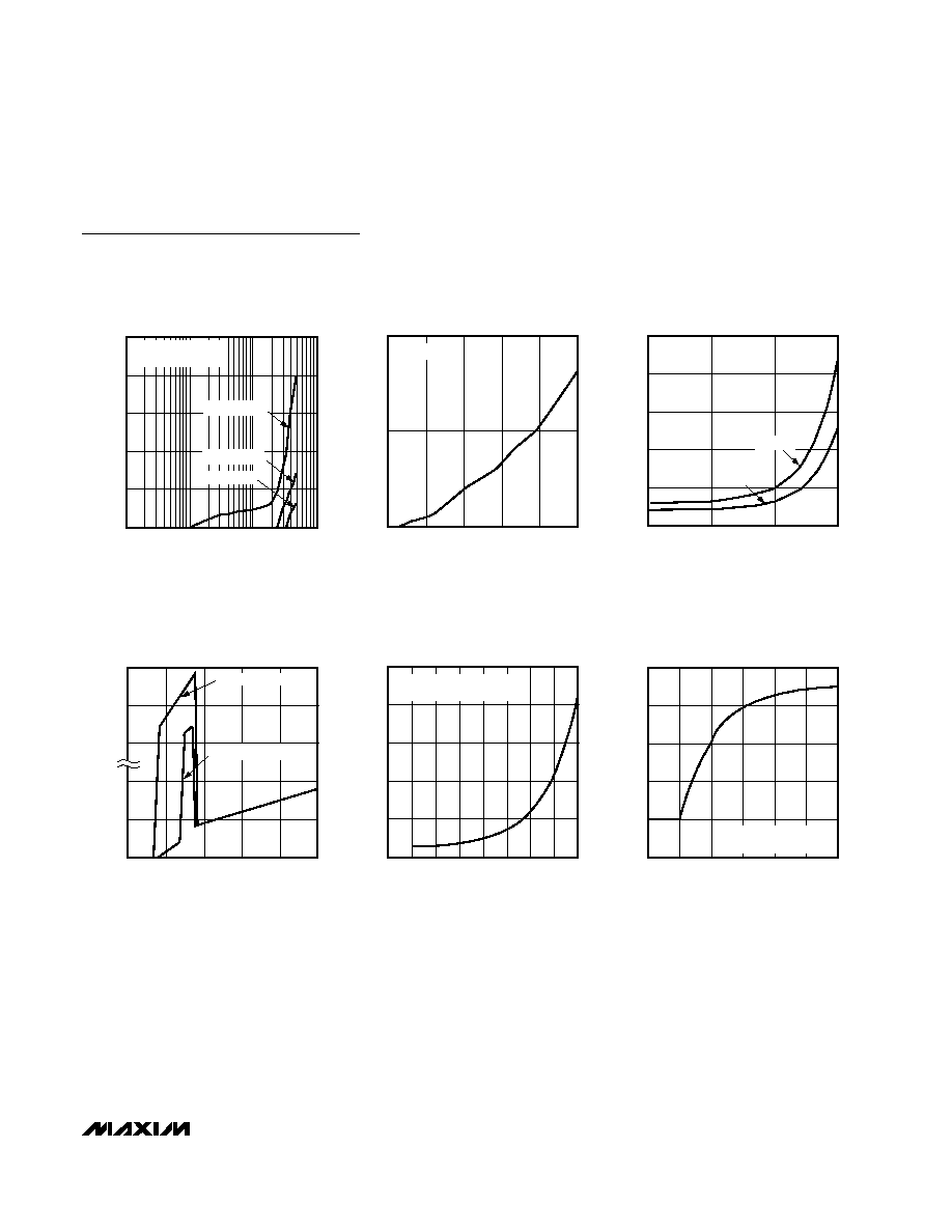
TEMPERATURE ERROR vs.
COMMON-MODE NOISE FREQUENCY
MAX1619-04
FREQUENCY (MHz)
TEMPERATURE ERROR (∞C)
0.1
10
100
1
V
IN
= 100mVp-p
V
IN
= SQUARE WAVE
AC-COUPLED TO DXN
V
IN
= 50mVp-p
V
IN
= 25mVp-p
0
10
20
0
40
60
80
20
100
TEMPERATURE ERROR vs.
DXP≠DXN CAPACITANCE
MAX1619-07
DXP≠DXN CAPACITANCE (nF)
TEMPERATURE ERROR (∞C)
V
CC
= 5V
0
100
400
200
300
500
0
1
0.0625
4
0.25
2
0.125
0.5
8
OPERATING SUPPLY CURRENT
vs. CONVERSION RATE
MAX1619-10
CONVERSION RATE (Hz)
SUPPLY CURRENT (
µ
A)
V
CC
= 5V
AVERAGED MEASUREMENTS
0
10
20
30
40
50
1
100
10
1000
STANDBY SUPPLY CURRENT
vs. CLOCK FREQUENCY
MAX1619-08
SMBCLK FREQUENCY (kHz)
SUPPLY CURRENT (
µ
A)
V
CC
= 5V
V
CC
= 3.3V
0
3
60
6
20
100
0
3
1
4
2
5
STANDBY SUPPLY CURRENT
vs. SUPPLY VOLTAGE
MAX1619-09
SUPPLY VOLTAGE (V)
SUPPLY CURRENT (
µ
A)
ADD0, ADD1 = GND
ADD0, ADD1 = HIGH-Z
0
25
100
50
75
125
-2
8
0
4
2
6
10
INTERNAL DIODE
RESPONSE TO THERMAL SHOCK
MAX1619-11
TIME (sec)
TEMPERATURE (∞C)
16-QSOP IMMERSED
IN +115∞C FLUORINERT BATH
Typical Operating Characteristics (continued)
(T
A
= +25∞C, unless otherwise noted.)