 | –≠–ª–µ–∫—Ç—Ä–æ–Ω–Ω—ã–π –∫–æ–º–ø–æ–Ω–µ–Ω—Ç: MAX1669 | –°–∫–∞—á–∞—Ç—å:  PDF PDF  ZIP ZIP |
For free samples & the latest literature: http://www.maxim-ic.com, or phone 1-800-998-8800.
For small orders, phone 1-800-835-8769.
General Description
The MAX1669 fan controller includes a precise digital
thermometer that reports the temperature of a remote
sensor. The remote sensor is a diode-connected transis-
tor--typically a low-cost, easily mounted 2N3906 PNP
type--replacing conventional thermistors or thermocou-
ples. Remote accuracy is ±3∞C for transistors from multi-
ple manufacturers, with no calibration needed. The
MAX1669 has an independent fan controller with a low-
current logic output requiring external power compo-
nents to interface to a DC brushless fan. The fan
controller has two modes of operation: a low-frequency
(20Hz to 160Hz) PWM mode intended for driving the fan
motor, or a high-impedance DAC output that generates
a variable DC control voltage. In PWM mode, the FAN
frequency can be synchronized to an external clock.
Other key features include general-purpose inputs/out-
puts (GPIOs) for fan presence detection and a thermo-
stat output intended as a fan override signal in case the
host system loses the ability to communicate. The inter-
nal ADC has a wide input voltage range and gives
overrange readings when too large an input voltage is
applied. Other error-checking includes temperature
out-of-range indication and diode open/short faults.
The MAX1669 is available in a space-saving 16-pin
QSOP package that allows it to fit adjacent to the
SLOT1 connector.
Applications
Pentium
Æ
CPU Cooling
Desktop Computers
Notebook Computers
Servers
Workstations
Features
o Measures Remote CPU Temperature
o No Calibration Required
o 20Hz to 160Hz PWM Output for Fan
o PWM Frequency Sync Input (260kHz)
o Flexible Fan Interface: Linear or PWM
o SMBus 2-Wire Serial Interface
o Programmable Under/Overtemperature Alarms
o ALERT Latched Interrupt Output
o OVERT Thermostat Output
o Two GPIO Pins
o Write-Once Configuration Protection
o Supports SMBus Alert Response
o ±3∞C Temperature Accuracy (-40∞C to +125∞C,
remote)
o 3µA Standby Supply Current
o +3V to +5.5V Supply Range
o Small 16-Pin QSOP Package
MAX1669
Fan Controller and Remote Temperature Sensor
with SMBus Serial Interface
________________________________________________________________ Maxim Integrated Products
1
16
15
14
13
12
11
10
9
1
2
3
4
5
6
7
8
I/O1
OVERT
ALERT
SMBDATA
SMBCLK
PGND
FAN
SYNC
V
CC
TOP VIEW
MAX1669
QSOP
I/O2
ADD0
AGND
ADD1
ADD2
DXN
DXP
19-1574; Rev 0; 1/00
PART
MAX1669EEE
-40∞C to +85∞C
TEMP. RANGE
PIN-PACKAGE
16 QSOP
Pentium is a registered trademark of Intel Corp.
Pin Configuration
Ordering Information
Typical Operating Circuit appears at end of data sheet.

MAX1669
Fan Controller and Remote Temperature Sensor
with SMBus Serial Interface
2
_______________________________________________________________________________________
ABSOLUTE MAXIMUM RATINGS
ELECTRICAL CHARACTERISTICS
(V
CC
= +3.3V, T
A
= 0∞C to +85∞C, unless otherwise noted. Typical values are at T
A
= +25∞C.)
Stresses beyond those listed under "Absolute Maximum Ratings" may cause permanent damage to the device. These are stress ratings only, and functional
operation of the device at these or any other conditions beyond those indicated in the operational sections of the specifications is not implied. Exposure to
absolute maximum rating conditions for extended periods may affect device reliability.
V
CC
to AGND...........................................................-0.3V to +6V
DXP, ADD_ to AGND.................................-0.3V to (V
CC
+ 0.3V)
DXN to AGND.......................................................-0.3V to +0.8V
SMBCLK, SMBDATA, ALERT, SYNC,
I/O1, I/O2, OVERT, FAN to AGND ......................-0.3V to +6V
FAN to PGND ............................................-0.3V to (V
CC
+ 0.3V)
PGND to AGND ....................................................-0.3V to +0.3V
PWM Current....................................................-50mA to +50mA
SMBDATA Current .............................................-1mA to +50mA
I/O1, I/O2 Current...............................................-1mA to +25mA
DXN Current ......................................................................±1mA
ESD Protection (all pins, Human Body Model) .................2000V
Continuous Power Dissipation (T
A
= +70∞C)
16-Pin QSOP (derate 8.30mW/∞C above +70∞C).......667mW
Operating Temperature Range (extended) ......-55∞C to +125∞C
Junction Temperature .....................................................+150∞C
Storage Temperature Range ............................-65∞C to +150∞C
Lead Temperature (soldering, 10s) ................................+300∞C
FAN output set to
DAC mode
FAN output set to
150Hz mode
T
R
= 0∞C to +100∞C, diode ideality factor = 1.013
High level
PWM mode, V
FAN
forced to 0.4V
PWM mode, V
FAN
forced to 2.9V
Monotonicity guaranteed
V
DXP
forced to V
DXN
+ 0.65V
SMBus static
Autoconvert mode
From stop bit to conversion complete
V
CC
, falling edge
V
CC
input, disables A/D conversion,
rising edge
Autoconvert mode,
average measured over 1s
CONDITIONS
mA
-10
FAN Output Sink Current
mA
10
FAN Output Source Current
V
0.7
DXN Source Voltage
80
100
120
µA
Remote-Diode Source Current
Hz
1.6
2
2.4
Conversion Rate
ms
47
62
78
Conversion Time
µA
360
µA
75
150
Average Operating Supply Current
∞C
Temperature Error, Remote Diode (Note 2)
Bits
8
Resolution (Note 1)
3
10
µA
Standby Supply Current
mV
50
POR Threshold Hysteresis
V
1
1.9 2.5
Power-On Reset Threshold
-3
3
V
3
5.5
Supply Voltage Range
V
2.6 2.8 2.95
Undervoltage Lockout Threshold
mV
50
Undervoltage Lockout Hysteresis
UNITS
MIN
TYP
MAX
PARAMETER
SMBCLK at 10kHz
3
Low level
8
10
12
ADC AND POWER SUPPLY
FAN OUTPUT

MAX1669
Fan Controller and Remote Temperature Sensor
with SMBus Serial Interface
_______________________________________________________________________________________
3
ELECTRICAL CHARACTERISTICS (continued)
(V
CC
= +3.3V, T
A
= 0∞C to +85∞C, unless otherwise noted. Typical values are at T
A
= +25∞C.)
Logic Input High Voltage
PARAMETER
MIN
TYP
MAX
UNITS
FAN PWM Frequency Error
-20
+20
%
FAN Total Unadjusted Error
-4
4
%FS
FAN Output Voltage High
2.96
3.06
V
CONDITIONS
PWM mode, any setting
DAC mode, any setting, R
L
= 10k
to GND
DAC mode, FAN duty factor = 1111b,
I
OUT
= 5mA
SYNC Input Low Period
500
ns
SYNC Input High Period
500
ns
SYNC Capture Range
140
260
400
kHz
2.1
V
Logic Input Low Voltage
0.8
V
SMBDATA, ALERT, OVERT, I/O1, I/O2
Output Low Sink Current
6
mA
FAN Output Voltage Low
0.05
0.2
V
ALERT, OVERT, I/O1, I/O2 Output
High Leakage Current
1
µA
Logic Input Current
-1
1
µA
SMBus Input Capacitance
5
pF
SMBus Clock Frequency
DC
100
kHz
SMBCLK Clock Low Time (t
LOW
)
4.7
µs
SMBCLK Clock High Time (t
HIGH
)
4
µs
SMBus Rise Time
1
µs
SMBus Fall Time
300
ns
SMBus Start Condition Setup Time
4.7
µs
SMBus Repeated Start Condition Setup
Time (t
SU:STA
)
500
ns
SMBus Start Condition Hold Time (t
HD:STA
)
4
µs
SMBus Stop Condition Setup Time (t
SU:STO
)
4
µs
SMBus Data Valid to SMBCLK
Rising-Edge Time (t
SU:DAT
)
250
ns
Pin forced to 5.5V
Logic inputs forced to V
CC
or GND
ADD_, I/O1, I/O2, SYNC, SMBCLK, SMBDATA;
V
CC
= 3V to 5.5V
ADD_, I/O1, I/O2, SYNC, SMBCLK, SMBDATA;
V
CC
= 3V to 5.5V
SMBCLK, SMBDATA
(Note 3)
Pin forced to 0.4V
10% to 10% points
90% to 90% points
SMBCLK, SMBDATA, 10% to 90% points
SMBCLK, SMBDATA, 90% to 10% points
90% to 90% points
DAC mode, FAN duty factor = 0000b,
I
OUT
= -5mA
10% of SMBDATA to 90% of SMBCLK
90% of SMBCLK to 10% of SMBDATA
10% or 90% of SMBDATA to 10% of SMBCLK
SMBus Data-Hold Time (
t
HD:DAT
)
0
µs
SMBus Bus-Free Time (t
BUF
)
4.7
µs
SMBCLK Falling Edge to SMBus
Data-Valid Time
1
µs
(Note 4)
Between start/stop conditions
Master clocking-in data
SMBus INTERFACE (Figures 7, 8)

Note 1: Guaranteed but not 100% tested.
Note 2: T
R
is the junction temperature of the remote diode. The temperature error specification is optimized to and guaranteed for a
diode-connected 2N3906 transistor with ideality factor = 1.013. Variations in the ideality factor "m" of the actual transistor
used will increase the temperature error by *. See the Temperature Error vs. Remote Diode Temperature graph in the
Typical Operating Characteristics for typical temperature errors using several random 2N3906s. See Remote Diode
Selection for remote diode forward-voltage requirements.
Note 3: The SMBus logic block is a static design that works with clock frequencies down to DC. While slow operation is possible, it
violates the 10kHz minimum clock frequency and SMBus specifications, and may monopolize the bus.
Note 4: Note that a transition must internally provide at least a hold time in order to bridge the undefined region (300ns max) of
SMBCLK's falling edge.
Note 5: Specifications to -40∞C are guaranteed by design and not production tested.
MAX1669
Fan Controller and Remote Temperature Sensor
with SMBus Serial Interface
4
_______________________________________________________________________________________
ELECTRICAL CHARACTERISTICS
(V
CC
= +3.3V, T
A
= -40∞C to +85∞C, unless otherwise noted.) (Note 5)
Pin forced to 0.4V
ADD_, I/O1, I/O2, SYNC, SMBCLK, SMBDATA;
V
CC
= 3V to 5.5V
ADD_, I/O1, I/O2, SYNC, SMBCLK, SMBDATA;
V
CC
= 3V to 5.5V
Logic inputs forced to V
CC
or GND
Pin forced to 5.5V
µA
-1
1
Logic Input Current
µA
1
ALERT, OVERT, I/O1, I/O2 Output
High Leakage Current
V
0.2
FAN Output Voltage Low
mA
6
SMBDATA, ALERT, OVERT, I/O1, I/O2
Output Low Sink Current
V
0.8
Logic Input Low Voltage
V
2.1
Logic Input High Voltage
DAC mode, FAN duty factor = 1111b,
I
OUT
= 5mA
DAC mode, any setting, R
L
= 10k
to GND
PWM mode, any setting
PWM mode, V
FAN
forced to 0.4V
PWM mode, V
FAN
forced to 2.9V
Monotonicity guaranteed
Autoconvert mode
From stop bit to conversion complete
T
R
= -55∞C to +125∞C, diode ideality factor = 1.013
Autoconvert mode, average measured over
1sec, FAN output set to 150Hz mode
CONDITIONS
V
2.94
FAN Output Voltage High
%FS
-5
5
FAN Total Unadjusted Error
%
-25
+25
FAN PWM Frequency Error
mA
-10
FAN Output Sink Current
mA
10
FAN Output Source Current
Hz
1.6
2.4
Conversion Rate
ms
47
Conversion Time
µA
100
Average Operating Supply Current
Bits
8
Temperature Resolution (Note 1)
∞C
-5
5
Temperature Error, Remote Diode (Note 2)
UNITS
MIN
MAX
PARAMETER
DAC mode, FAN duty factor = 0000b,
I
OUT
= -5mA
V
3
5.5
Supply Voltage Range
ADC AND POWER SUPPLY
FAN OUTPUT
SMBus INTERFACE
*
.
.
T
m
k
T
C
R
=
-
+
(
)
∞
( )
1 013
1
273 15
MAX1669
Fan Controller and Remote Temperature Sensor
with SMBus Serial Interface
_______________________________________________________________________________________
5
40
-30
1
10
100
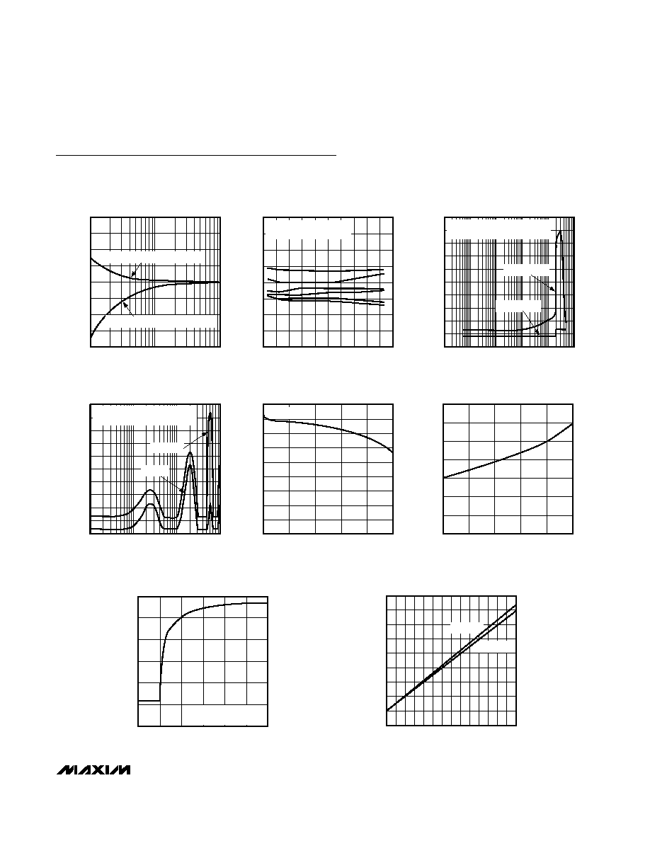
TEMPERATURE ERROR
vs. LEAKAGE RESISTANCE
-10
MAX1669-01
LEAKAGE RESISTANCE (M
)
TEMPERATURE ERROR (∞C)
10
30
-40
-20
0
20
PATH = DXP TO V
CC
(5V); CONFIG = 02h
PATH = DXP TO GND; CONFIG = 02h
-2.0
-1.0
-1.5
0.5
0
-0.5
1.5
1.0
2.0
-60
20
-20
60
100
-40
40
0
80
120 140
TEMPERATURE ERROR
vs. REMOTE DIODE TEMPERATURE
MAX1669-02
TEMPERATURE (∞C)
TEMPERATURE ERROR (
∞
C)
RANDOM 2N3906s FROM
DIFFERENT MANUFACTURERS
18
-2
1K
10K
100K
1M
10M
100M
TEMPERATURE ERROR vs.
POWER-SUPPLY NOISE FREQUENCY
2
0
MAX1669-03
PSNF (Hz)
TEMPERATURE ERROR (
∞
C)
6
14
10
4
8
16
12
V
IN
= SQUARE WAVE APPLIED TO
V
CC
WITH NO 0.1
µF V
CC
CAPACITOR
V
IN
= 100mVp-p
V
IN
= 250mVp-p
7
-2
1M
1G
100M
10M
TEMPERATURE ERROR vs.
COMMON-MODE NOISE FREQUENCY
1
-1
5
3
8
2
0
6
4
MAX1669-04
FREQUENCY (Hz)
TEMPERATURE ERROR (
∞
C)
V
IN
= 50mVp-p AC-COUPLED TO DXN
C = DXN - DXP CAPACITANCE
C = 27nF
C = 2200pF
-16
-12
-14
-6
-8
-10
0
-2
-4
2
0
20
10
30
40
50
TEMPERATURE ERROR
vs. DXP - DXN CAPACITANCE
MAX1669-05
DXP-DXN CAPACITANCE (nF)
TEMPERATURE ERROR (
∞
C)
V
CC
= 5V
0
2
1
4
3
6
5
7
3.0
4.0
3.5
4.5
5.0
5.5
STANDBY SUPPLY CURRENT
vs. SUPPLY VOLTAGE
MAX1669-06
SUPPLY VOLTAGE (V)
STANDBY SUPPLY CURRENT (
µ
A)
0
40
20
80
60
100
120
-2
2
4
0
6
8
10
RESPONSE TO THERMAL SHOCK
MAX1669-07
TIME (sec)
TEMPERATURE (
∞
C)
CMPT3906 IMMERSED IN
+115∞C FLUORINERT BATH
0
20
60
40
80
120
100
140
160
180
0
4
2
5
7 8
10
12
3
1
6
9
11
13 14
PWM FREQUENCY vs. CODE (F3F2F1F0)
MAX1669-08
CODE (F3F2F1F0)
PWM FREQUENCY (Hz)
V
CC
= +3.3V
V
CC
= +5V
Typical Operating Characteristics
(Temperature error = measured - actual, T
A
= +25∞C, unless otherwise noted.)