 | –≠–ª–µ–∫—Ç—Ä–æ–Ω–Ω—ã–π –∫–æ–º–ø–æ–Ω–µ–Ω—Ç: MAX16801B | –°–∫–∞—á–∞—Ç—å:  PDF PDF  ZIP ZIP |
General Description
The MAX16801A/B/MAX16802A/B high-brightness (HB)
LED driver-control ICs contain all the circuitry required
for the design of wide-input voltage range LED drivers
for general lighting and display applications. The
MAX16801 is well suited for universal input (rectified
85VAC to 265VAC) LED drivers, while the MAX16802 is
intended for low-input-voltage (10.8VDC to 24VDC) LED
drivers.
When the LED current needs to be tightly regulated, an
additional on-board error amplifier with 1% accurate ref-
erence can be utilized. A wide dimming range can be
implemented by using low-frequency PWM dimming.
The MAX16801/MAX16802 feature an input undervoltage
lockout (UVLO) for programming the input-supply start
voltage, and to ensure proper operation during brownout
conditions. The MAX16801 has an internal-bootstrap
undervoltage lockout circuit with a large hysteresis that
simplifies off-line LED driver designs. The MAX16802
does not have this internal bootstrap circuit and can be
biased directly from a +12V rail.
The 262kHz fixed switching frequency is internally
trimmed, allowing for optimization of the magnetic and fil-
ter components, resulting in a compact, cost-effective
LED driver.The MAX16801A/MAX16802A are offered with
50% maximum duty cycle. The MAX16801B/MAX16802B
are offered with 75% maximum duty cycle. These devices
are available in an 8-pin µMAX
Æ
package and operate
over the -40∞C to +85∞C temperature range.
Applications
Features
Suitable for Buck, Boost, Flyback, SEPIC, and
Other Topologies
Up to 50W or Higher Output Power
Universal Off-Line Input Voltage Range: Rectified
85VAC to 265VAC (MAX16801)
IN-Pin Directly Driven From 10.8VDC to 24VDC
Input (MAX16802)
Internal Error Amplifier with 1% Accurate
Reference for Precise LED Current Regulation
PWM or Linear Dimming
Fixed Switching Frequency of 262kHz ±12%
Thermal Shutdown
Digital Soft-Start
Programmable Input Startup Voltage
Internal Bootstrap UVLO with Large Hysteresis
(MAX16801)
45µA (typ) Startup Supply Current, 1.4mA (typ)
Operating Supply Current
50% (MAX16801A/MAX16802A) or 75%
(MAX16801B/MAX16802B) Maximum Duty Cycle
Available in a Tiny 8-Pin µMAX Package
MAX16801A/B/MAX16802A/B
Off-Line and DC-DC PWM Controllers for
High-Brightness LED Drivers
________________________________________________________________ Maxim Integrated Products
1
Ordering Information
19-3880; Rev 0; 10/05
For pricing, delivery, and ordering information, please contact Maxim/Dallas Direct! at
1-888-629-4642, or visit Maxim's website at www.maxim-ic.com.
PART
TEMP
RANGE
PIN-
PACKAGE
MAX16801AEUA+
-40∞C to +85∞C
8 µMAX
MAX16801BEUA+
-40∞C to +85∞C
8 µMAX
MAX16802AEUA+*
-40∞C to +85∞C
8 µMAX
MAX16802BEUA+
-40∞C to +85∞C
8 µMAX
+Denotes lead-free package.
*Future product≠contact factory for availability.
Off-Line and DC-DC
LED Drivers
RGB Back Light for LCD
TVs and Monitors
Commercial and
Industrial Lighting
Decorative and
Architectural Lighting
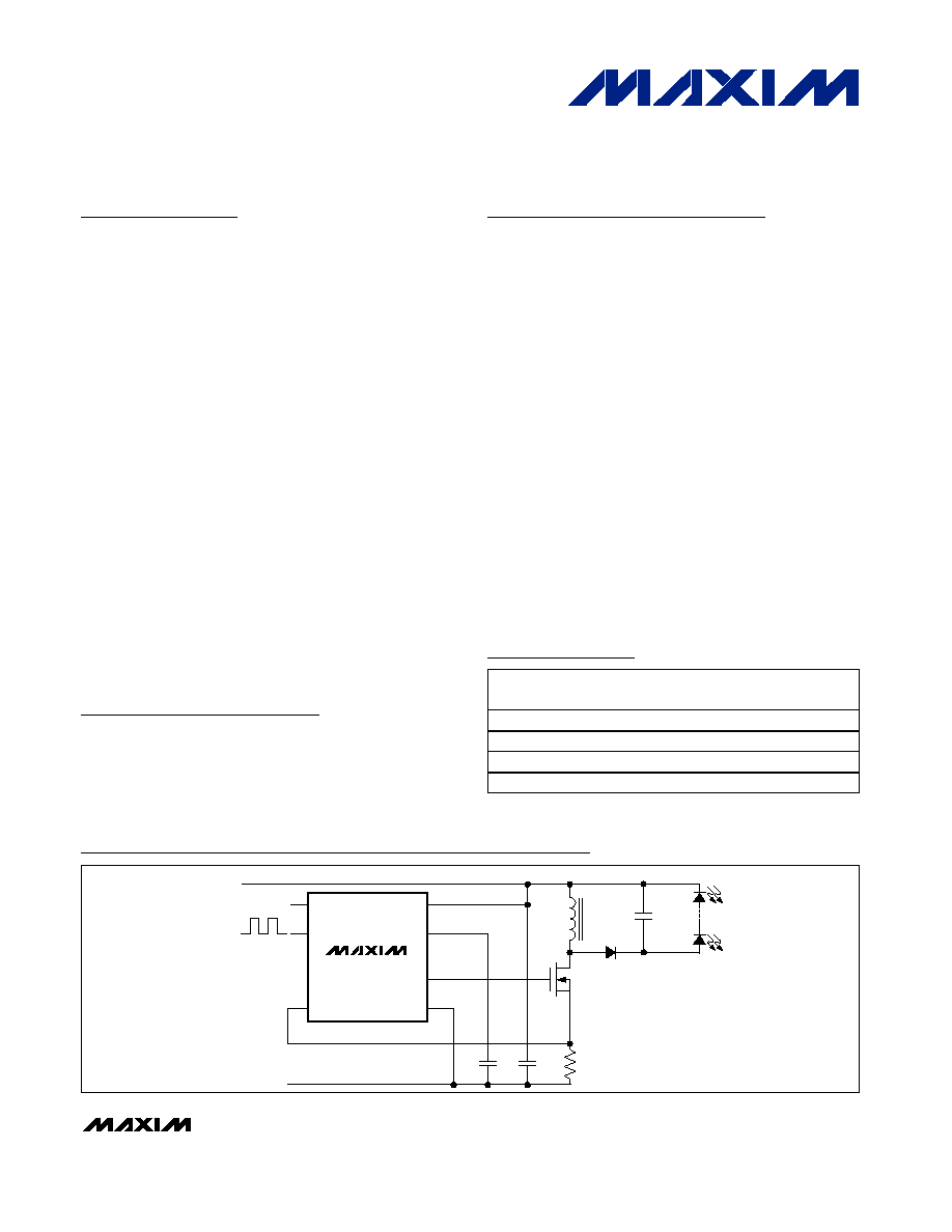
Q1
MAX16802B
10.8VDC TO 24VDC
PWM
GND
U1
C1
R1
L1
D1
C2
C3
LEDs
CS
COMP
DIM/FB
UVLO/EN
IN
VCC
NDRV
GND
ENABLE
Typical Operating Circuit
Warning: The MAX16801/MAX16802 are designed to work with high voltages. Exercise caution.
µMAX is a registered trademark of Maxim Integrated Products, Inc.

MAX16801A/B/MAX16802A/B
Off-Line and DC-DC PWM Controllers for
High-Brightness LED Drivers
2
_______________________________________________________________________________________
ABSOLUTE MAXIMUM RATINGS
ELECTRICAL CHARACTERISTICS
(V
IN
= +12V (MAX16801: V
IN
must first be brought up to +23.6V for startup), 10nF bypass capacitors at IN and VCC, C
NDRV
= 0,
V
UVLO
= +1.4V, V
DIM/FB
= +1.0V, COMP = unconnected, V
CS
= 0V, T
A
= -40∞C to +85∞C, unless otherwise noted. Typical values are
at T
A
= +25∞C.) (Note 1)
Stresses beyond those listed under "Absolute Maximum Ratings" may cause permanent damage to the device. These are stress ratings only, and functional
operation of the device at these or any other conditions beyond those indicated in the operational sections of the specifications is not implied. Exposure to
absolute maximum rating conditions for extended periods may affect device reliability.
IN to GND
..........................................................................
-0.3V to +30V
VCC to GND
.....................................................................
-0.3V to +13V
DIM/FB, COMP, UVLO, CS to GND..........................-0.3V to +6V
NDRV to GND.............................................-0.3V to (V
CC
+ 0.3V)
Continuous Power Dissipation (T
A
= +70∞C)
8-Pin µMAX (derate 4.5mW/∞C above +70∞C) ..............362mW
Operating Temperature Range ...........................-40∞C to +85∞C
Storage Temperature Range ............................-65∞C to +150∞C
Junction Temperature ......................................................+150∞C
Lead Temperature (soldering, 10s) .................................+300∞C
PARAMETER
SYMBOL
CONDITIONS
MIN
TYP
MAX
UNITS
UNDERVOLTAGE LOCKOUT/STARTUP
Bootstrap UVLO Wake-Up Level
V
SUVR
V
IN
rising (MAX16801 only)
19.68
21.6
23.60
V
Bootstrap UVLO Shutdown Level
V
SUVF
V
IN
falling (MAX16801 only)
9.05
9.74
10.43
V
UVLO/EN Wake-Up Threshold
V
ULR2
UVLO/EN rising
1.188
1.28
1.371
V
UVLO/EN Shutdown Threshold
V
ULF2
UVLO/EN falling
1.168
1.23
1.291
V
UVLO/EN Input Current
I
UVLO
T
J
= +125∞C
25
nA
UVLO/EN Hysteresis
50
mV
IN Supply Current In
Undervoltage Lockout
I
START
V
IN
= +19V, for MAX16801 only when in
bootstrap UVLO
45
90
µA
IN Voltage Range
V
IN
10.8
24
V
t
EXTR
UVLO/EN steps up from +1.1V to +1.4V
12
UVLO/EN Propagation Delay
t
EXTF
UVLO/EN steps down from +1.4V to +1.1V
1.8
µs
t
BUVR
V
IN
steps up from +9V to +24V
5
Bootstrap UVLO Propagation
Delay
t
BUVF
V
IN
steps down from +24V to +9V
1
µs
INTERNAL SUPPLY
VCC Regulator Set Point
V
CCSP
V
IN
= +10.8V to +24V, sinking 1µA to 20mA
from V
CC
7
10.5
V
IN Supply Current After Startup
I
IN
V
IN
= +24V
1.4
2.5
mA
Shutdown Supply Current
UVLO/EN = low
90
µA
GATE DRIVER
R
ON(LOW)
Measured at NDRV sinking, 100mA
2
4
Driver Output Impedance
R
ON(HIGH)
Measured at NDRV sourcing, 20mA
4
12
Driver Peak Sink Current
1
A
Driver Peak Source Current
0.65
A
PWM COMPARATOR
Comparator Offset Voltage
VO
PWM
V
COMP
- V
CS
1.15
1.38
1.70
V
CS Input Bias Current
I
CS
V
CS
= 0V
-2
+2
µA
Comparator Propagation Delay
t
PWM
V
CS
= +0.1V
60
ns
Minimum On-Time
t
ON(MIN)
150
ns

MAX16801A/B/MAX16802A/B
Off-Line and DC-DC PWM Controllers for
High-Brightness LED Drivers
_______________________________________________________________________________________
3
Note 1: All devices are 100% tested at T
A
= +85∞C. All limits over temperature are guaranteed by characterization.
Note 2: V
REF
is measured with DIM/FB connected to the COMP pin (see the Functional Diagram).
Note 3: The MAX16801 is intended for use in universal input off-line drivers. The internal clamp circuit is used to prevent the boot-
strap capacitor (C1 in Figure 5) from charging to a voltage beyond the absolute maximum rating of the device when
EN/UVLO is low. The maximum current to IN (hence to clamp) when UVLO is low (device in shutdown), must be externally
limited to 2mA (max). Clamp currents higher than 2mA may result in clamp voltage higher than +30V, thus exceeding the
absolute maximum rating for IN. For the MAX16802, do not exceed the +24V maximum operating voltage of the device.
ELECTRICAL CHARACTERISTICS (continued)
(V
IN
= +12V (MAX16801: V
IN
must first be brought up to +23.6V for startup), 10nF bypass capacitors at IN and VCC, C
NDRV
= 0,
V
UVLO
= +1.4V, V
DIM/FB
= +1.0V, COMP = unconnected, V
CS
= 0V, T
A
= -40∞C to +85∞C, unless otherwise noted. Typical values are
at T
A
= +25∞C.) (Note 1)
PARAMETER
SYMBOL
CONDITIONS
MIN
TYP
MAX
UNITS
CURRENT-SENSE COMPARATOR
Current-Sense Trip Threshold
V
CS
262
291
320
mV
CS Input Bias Current
I
CS
V
CS
= 0V
-2
+2
µA
Propagation Delay From
Comparator Input to NDRV
t
PWM
50mV overdrive
60
ns
Switching Frequency
f
SW
230
262
290
kHz
MAX1680_A
50
50.5
Maximum Duty Cycle
D
MAX
MAX1680_B
75
76
%
IN CLAMP VOLTAGE
IN Clamp Voltage
V
INC
2mA sink current, MAX16801 only (Note 3)
24.1
26.1
29.0
V
ERROR AMPLIFIER
Voltage Gain
R
LOAD
= 100k
80
dB
Unity Gain Bandwidth
R
LOAD
= 100k
, C
LOAD
= 200pF
2
MHz
Phase Margin
R
LOAD
= 100k
, C
LOAD
= 200pF
65
degrees
DIM/FB Input Offset Voltage
3
mV
High
2.2
3.5
COMP Pin Clamp Voltage
Low
0.4
1.1
V
Source Current
0.5
mA
Sink Current
0.5
mA
Reference Voltage
V
REF
(Note 2)
1.218
1.230
1.242
V
Input Bias Current
50
nA
COMP Short-Circuit Current
8
mA
THERMAL SHUTDOWN
Thermal-Shutdown Temperature
130
∞C
Thermal Hysteresis
25
∞C
DIGITAL SOFT-START
Soft-Start Duration
15,872
clock
cycles
Reference Voltage Steps During
Soft-Start
31
steps
Reference Voltage Step
40
mV

MAX16801A/B/MAX16802A/B
Off-Line and DC-DC PWM Controllers for
High-Brightness LED Drivers
4
_______________________________________________________________________________________
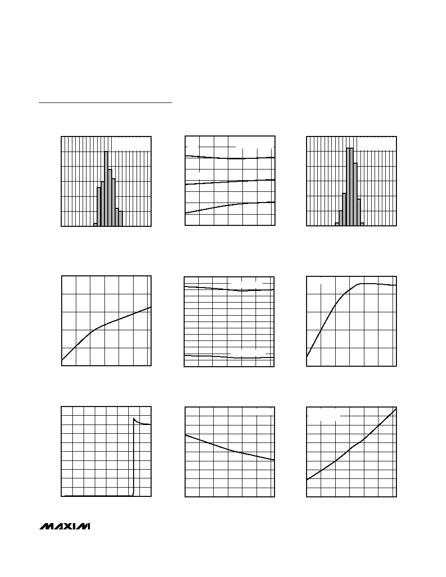
Typical Operating Characteristics
(V
UVLO/EN
= +1.4V, V
FB
= +1V, COMP = unconnected, V
CS
= 0V, T
A
= +25∞C, unless otherwise noted.)
BOOTSTRAP UVLO WAKE-UP LEVEL
vs. TEMPERATURE
MAX16801 toc01
TEMPERATURE (
∞C)
V
IN
(V)
60
40
20
0
-20
21.35
21.40
21.45
21.50
21.55
21.60
21.30
-40
80
MAX16801 V
IN
RISING
BOOTSTRAP UVLO SHUTDOWN LEVEL
vs. TEMPERATURE
MAX16801 toc02
TEMPERATURE (
∞C)
V
IN
(V)
60
40
20
0
-20
9.8
9.9
10.0
10.1
9.7
-40
80
MAX16801 V
IN
FALLING
UVLO/EN WAKE-UP THRESHOLD
vs. TEMPERATURE
MAX16801 toc03
TEMPERATURE (
∞C)
UVLO/EN (V)
60
40
20
0
-20
1.255
1.260
1.265
1.270
1.275
1.280
1.250
-40
80
UVLO/EN RISING
UVLO/EN SHUTDOWN THRESHOLD
vs. TEMPERATURE
MAX16801 toc04
TEMPERATURE (
∞C)
UVLO/EN (V)
60
40
20
0
-20
1.15
1.20
1.25
1.30
1.10
-40
80
UVLO/EN FALLING
V
IN
SUPPLY CURRENT IN UNDERVOLTAGE
LOCKOUT vs. TEMPERATURE
MAX16801 toc05
TEMPERATURE (
∞C)
I
START
(
µ
A)
60
40
20
0
-20
43
44
45
46
47
48
49
50
51
52
42
-40
80
V
IN
= 19V
MAX16801 WHEN IN BOOTSTRAP UVLO
MAX16802 WHEN UVLO/EN IS LOW
V
IN
SUPPLY CURRENT AFTER STARTUP
vs. TEMPERATURE
MAX16801 toc06
TEMPERATURE (
∞C)
I
IN
(mA)
60
40
20
0
-20
1.2
1.3
1.4
1.5
1.1
-40
80
V
IN
= 24V
V
CC
REGULATOR SET POINT
vs. TEMPERATURE
MAX16801 toc07
TEMPERATURE (
∞C)
V
CC
(V)
60
40
20
0
-20
9.3
9.5
9.4
9.7
9.6
9.8
9.2
-40
80
V
IN
= 19V
NO LOAD
NDRV OUTPUT IS NOT
SWITCHING, V
FB
= 1.5V
NDRV OUTPUT IS
SWITCHING
V
CC
REGULATOR SET POINT
vs. TEMPERATURE
MAX116801 toc08
TEMPERATURE (
∞C)
V
CC
(V)
60
40
20
0
-20
8.2
8.5
8.6
8.4
8.3
8.8
8.7
8.9
8.1
-40
80
V
IN
= 10.8V
10mA LOAD
20mA LOAD
CURRENT-SENSE THRESHOLD
vs. TEMPERATURE
MAX16801 toc09
TEMPERATURE (
∞C)
CURRENT-SENSE THRESHOLD (
µ
V)
60
40
20
0
-20
275
290
295
285
280
305
300
310
270
-40
80
+3
-3
MEAN
TOTAL NUMBER OF
DEVICES = 100
MAX16801A/B/MAX16802A/B
Off-Line and DC-DC PWM Controllers for
High-Brightness LED Drivers
_______________________________________________________________________________________
5
CURRENT-SENSE THRESHOLD
MAX16801 toc10
CURRENT-SENSE THRESHOLD (mV)
PERCENTAGE OF UNITS (%)
310
300
290
280
270
5
10
15
20
25
30
0
260
320
TOTAL NUMBER OF
DEVICES = 200
SWITCHING FREQUENCY
vs. TEMPERATURE
MAX16801 toc11
TEMPERATURE (
∞C)
SWITCHING FREQUENCY (kHz)
60
40
20
0
-20
245
260
265
255
250
275
270
280
240
-40
80
+3
-3
MEAN
TOTAL NUMBER OF
DEVICES = 100
SWITCHING FREQUENCY
MAX16801 toc12
SWITCHING FREQUENCY (kHz)
PERCENTAGE OF UNITS (%)
280
270
260
250
240
5
10
15
20
25
30
0
230
290
TOTAL NUMBER OF
DEVICES = 200
PROPAGATION DELAY FROM
CURRENT-SENSE COMPARATOR INPUT
TO NDRV vs. TEMPERATURE
MAX16801 toc13
TEMPERATURE (
∞C)
t
PWM
(ns)
60
40
20
0
-20
55
60
65
70
75
50
-40
80
UVLO/EN PROPAGATION DELAY
vs. TEMPERATURE
MAX16801 toc14
TEMPERATURE (
∞C)
UNDERVOLTAGE LOCKOUT DELAY (
µ
s)
60
40
20
0
-20
4
3
2
1
7
6
5
13
12
11
10
9
8
14
0
-40
80
UVLO/EN RISING
UVLO/EN FALLING
REFERENCE VOLTAGE
vs. TEMPERATURE
MAX16801 toc15
TEMPERATURE (
∞C)
REFERENCE VOLTAGE (V)
60
40
20
0
-20
1.226
1.227
1.228
1.229
1.230
1.225
-40
80
V
IN
= 12V
INPUT CURRENT
vs. INPUT CLAMP VOLTAGE
MAX16801 toc16
INPUT VOLTAGE (V)
INPUT CURRENT (mA)
27.5
25.0
20.0 22.5
15.0 17.5
12.5
1
2
3
4
5
6
7
8
9
10
0
10.0
30.0
INPUT CLAMP VOLTAGE
vs. TEMPERATURE
MAX16801 toc17
TEMPERATURE (
∞C)
INPUT CLAMP VOLTAGE (V)
60
40
20
0
-20
25.2
25.4
25.6
25.8
26.0
26.2
26.4
26.6
26.8
27.0
25.0
-40
80
I
IN
= 2mA
NDRV OUTPUT IMPEDANCE
vs. TEMPERATURE
MAX16801 toc18
TEMPERATURE (
∞C)
R
ON
(
)
60
40
20
0
-20
1.3
1.4
1.5
1.6
1.7
1.8
1.9
2.0
2.1
2.2
1.2
-40
80
V
IN
= 24V
SINKING 100mA
Typical Operating Characteristics (continued)
(V
UVLO/EN
= +1.4V, V
FB
= +1V, COMP = unconnected, V
CS
= 0V, T
A
= +25∞C, unless otherwise noted.)