 | ÐлекÑÑоннÑй компоненÑ: MAX1736 | СкаÑаÑÑ:  PDF PDF  ZIP ZIP |
Äîêóìåíòàöèÿ è îïèñàíèÿ www.docs.chipfind.ru
General Description
The MAX1736 is a simple, low-cost, single-cell lithium-
ion (Li+) battery charger for small hand-held applica-
tions. When accompanied by a current-limited voltage
source (such as a wall cube), the MAX1736 provides
simple, accurate charging and termination control for
single-cell Li+ batteries. The MAX1736EUT42 is preset
to a 4.2V battery regulation voltage, while the
MAX1736EUT41 is preset to 4.1V.
The MAX1736 initiates charging in one of four ways:
battery insertion, charger power-up, battery voltage
threshold, and by external manipulation of the EN pin.
The device features an internal precharge current
source that safely charges near-dead cells, as well as
input-supply detection that shuts down the MAX1736
when the supply is removed to minimize battery current
drain.
The MAX1736 accepts input voltages up to 22V, mak-
ing it compatible with a wide range of input supplies. It
has a single control input yet offers stand-alone and
microprocessor-controlled operation. The MAX1736 is
packaged in a small SOT23-6 package. An evaluation
kit (EV kit) is available to reduce design time.
________________________Applications
Single-Cell Li+ Portable Applications
Wireless Handsets
Personal Digital Assistants
Digital Cameras
Small Hand-Held Equipment
Self-Charging Battery Packs
Cradle Chargers
Features
o Small 6-Pin SOT23 Package
o Stand-Alone or µP-Controlled Operation
o 0.5% Voltage Set-Point Accuracy
o Lowest Power Dissipation
o Low 4.7V min Input Voltage
o Top-Off Charging to Achieve Full Battery Capacity
o No Inductor Required
o Safely Precharges Near-Dead Cells
o Automatic Power-Down when Input Power
Removed
Note: Requires special solder temperature profile
described in the Absolute Maximum Ratings Section.
MAX1736
SOT23, Single-Cell Li+ Battery
Charger for Current-Limited Supply
________________________________________________________________ Maxim Integrated Products
1
GATE
EN
GND
1
6
BATT
5
CT
IN
MAX1736
SOT23
TOP VIEW
2
3
4
Pin Configuration
CURRENT-LIMITED
VOLTAGE SOURCE
GATE
BATT
BATTERY
GND
IN
EN
CT
ON
OFF
MAX1736
PFET
Typical Operating Circuit
19-1662; Rev 1; 10/00
EVALUATION KIT
AVAILABLE
Ordering Information
PART
TEMP.
RANGE
PIN-
PACKAGE
SOT
MARK
MAX1736EUT42-T
-40
°C to +85°C 6 SOT23-6
AAHO
MAX1736EUT41-T
-40
°C to +85°C 6 SOT23-6
AANC
For price, delivery, and to place orders, please contact Maxim Distribution at 1-888-629-4642,
or visit Maxim's website at www.maxim-ic.com.
MAX1736
SOT23, Single-Cell Li+ Battery Charger
for Current-Limited Supply
2
_______________________________________________________________________________________
ABSOLUTE MAXIMUM RATINGS
Stresses beyond those listed under "Absolute Maximum Ratings" may cause permanent damage to the device. These are stress ratings only, and functional
operation of the device at these or any other conditions beyond those indicated in the operational sections of the specifications is not implied. Exposure to
absolute maximum rating conditions for extended periods may affect device reliability.
IN, GATE to GND....................................................-0.3V to +26V
BATT, EN, CT to GND ..............................................-0.3V to +6V
GATE to IN................................................................-6V to +0.3V
GATE Continuous Current.................................-10mA to +10mA
Continuous Power Dissipation (T
A
= +70
°C) (Note 1)
6-Pin SOT23 (derate 8.1mW/
°C above +70°C).............0.65W
Operating Temperature Range ...........................-40°C to +85
°C
Storage Temperature Range ..............................-65°C to +150
°C
Maximum Junction Temperature ......................................+150
°C
Lead Temperature (soldering, 10s) (Note 2) ...................+300
°C
ELECTRICAL CHARACTERISTICS
(V
IN
= 10V, V
BATT
= 4.2V for MAX1736EUT42 or 4.1V for MAX1736EUT41, T
A
= 0
°C to +85°C. Typical values are at T
A
= +25
°C,
unless otherwise noted.) (Note 3)
PARAMETER
CONDITIONS
MIN
TYP
MAX
UNITS
Input Voltage (Note 4)
External P-MOSFET off
4.7
22
V
Fast-Charge BATT Qualification
Threshold
BATT rising, transition from precharge to fast charge
2.4
2.5
2.65
V
Fast-Charge BATT Qualification
Threshold Hysteresis
70
mV
MAX1736EUT42
4.179
4.20
4.221
BATT Regulation Voltage
MAX1736EUT41
4.079
4.10
4.121
V
BATT Removal Detection
Threshold
BATT rising
4.875
5.0
5.1
V
BATT Removal Detection
Threshold Hysteresis
125
mV
BATT Input Current, Input Power
Removed
V
IN
V
BATT
- 0.3V
0.1
1
µA
BATT Input Current, Charger
Disabled
EN = GND, V
BATT
= 0 to 5V
2
6
µA
BATT Input Current, When
Charging
0.4
0.75
mA
Precharge Source Current
V
BATT
= 2V
3.5
6
8
mA
IN Input Current
0.25
1
mA
IN Detection Interval (Note 5)
C
CT
= 0.33µF
20
s
GATE Source/Sink Current
75
100
125
µA
GATE Drive Source Current at
Battery Removal
V
BATT
= 5.1V
15
30
60
mA
Minimum BATT Bypass
Capacitance (Note 6)
1.5
µF/A
EN Logic High Threshold
2
V
EN Logic Low Threshold
0.7
V
CT Pulldown Current
1.6
2
2.4
µA
Note 1: Thermal properties are specified with product mounted on PC board with one square-inch of copper area and still air.
Note 2: This device is constructed using a unique set of packaging techniques that impose a limit on the termal profile the device can be
exposed to during solder attach and rework. This limit permits only the use of the solder profiles recommended in the industry stan-
dard specification, IPC/JEDEC J-STD-020A, paragraph 7.6, Table 3 for the IR/VPR and Convention reflow. Pre-heating is required.
Hand or wave soldering is not allowed.
MAX1736
SOT23, Single-Cell Li+ Battery Charger
for Current-Limited Supply
_______________________________________________________________________________________
3
ELECTRICAL CHARACTERISTICS (continued)
(V
IN
= 10V, V
BATT
= 4.2V for MAX1736EUT42 or 4.1V for MAX1736EUT41, T
A
= 0°C to +85°C. Typical values are at T
A
= +25°C,
unless otherwise noted.)
ELECTRICAL CHARACTERISTICS
(V
IN
= 10V, V
BATT
= 4.2V for MAX1736EUT42 or 4.1V for MAX1736EUT41, T
A
= -40°C to +85°C, unless otherwise noted.) (Note 3)
PARAMETER
CONDITIONS
MIN
TYP
MAX
UNITS
CT Pullup Current
-12
-10
-8
µA
Minimum On-Time
C
CT
= 0.33µF
165
ms
Minimum Off-Time
C
CT
= 0.33µF
33
ms
EN Pullup Resistance
175
350
725
k
PARAMETER
CONDITIONS
MIN
MAX
UNITS
Input Voltage (Note 4)
External P-MOSFET off
4.7
22
V
Fast-Charge BATT Qualification
Threshold
BATT rising, transition from precharge to fast charge
2.4
2.65
V
MAX1736EUT42
4.158
4.242
V
BATT Regulation Voltage
MAX1736EUT41
4.058
4.142
BATT Removal Detection
Threshold
BATT rising
4.85
5.125
V
BATT Input Current, Input Power
Removed
VIN
VBATT - 0.3V
1
µA
BATT Input Current, Charger
Disabled
EN = GND, VBATT = 0 to 5V
6
µA
BATT Input Current, When
Charging
0.75
mA
Precharge Source Current
VBATT = 2V
3
8
mA
IN Input Current
1
mA
GATE Source/Sink Current
60
140
µA
GATE Drive Source Current at
Battery Removal
VBATT
= 5.1V
10
90
mA
EN Logic High Threshold
2
V
EN Logic Low Threshold
0.7
V
CT Pulldown Current
1.5
2.5
µA
CT Pullup Current
-12
-8
µA
EN Pullup Resistance
170
725
k
Note 3: All devices are 100% production tested at T
A
= +25°C. Limits over the operating temperature range are guaranteed by
design.
Note 4: The input voltage range is specified with the external PFET off. When charging, the PFET turns on and the input voltage (the
output voltage of the constant-current power source) drops to very near the battery voltage. When the PFET is on, IN may be
as low as 2.5V.
Note 5: Every 20s (for CT = 0.33µF) the MAX1736 turns off the external P-channel MOSFET and samples IN to determine if input
power is present. If input power is removed, the charger shuts down.
Note 6: For design guidance, not tested.
MAX1736
SOT23, Single-Cell Li+ Battery Charger
for Current-Limited Supply
4
_______________________________________________________________________________________
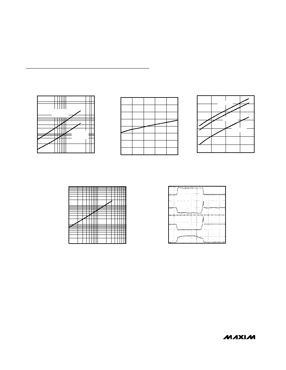
0.1
1
10
MINIMUM ON/OFF-TIMES vs. C
CT
MAX1736 toc01
C
CT
(
µF)
MINIMUM ON/OFF-TIME (ms)
10
100
1000
10,000
MINIMUM
OFF-TIME
MINIMUM
ON-TIME
-0.20
-0.15
-0.10
-0.05
0.00
0.05
0.10
0.15
0.20
-40
-15
10
35
60
85
BATT REGULATION VOLTAGE
DEVIATION vs. TEMPERATURE
MAX1736-02
TEMPERATURE (°C)
BATT VOLTAGE DEVIATION (%)
5.1
5.3
5.2
5.5
5.4
5.7
5.6
5.8
PRECHARGE CURRENT vs.
INPUT VOLTAGE
MAX1736-03
V
IN
(V)
PRECHARGE CURRENT (mA)
4
9
14
19
24
V
BATT
= 2V
V
BATT
= 1V
V
BATT
= 0
PRECHARGE CURRENT (mA)
0.1
1
10
INPUT DETECTION INTERVAL vs. C
CT
MAX1736 toc04
C
CT
(µF)
INPUT DETECTION INTERVAL (s)
1000
1
10
100
OA
OV
V
BATT
200mV/div
I
IN
1A/div
I
IN
5V/div
V
GATE
10V/div
TYPICAL OPERATING WAVEFORMS
MAX1736 toc05
10ms/div
AC-COUPLED
PFET OFF
PFET ON
Typical Operating Characteristics
(T
A
= +25°C, unless otherwise noted.)
MAX1736
SOT23, Single-Cell Li+ Battery Charger
for Current-Limited Supply
_______________________________________________________________________________________
5
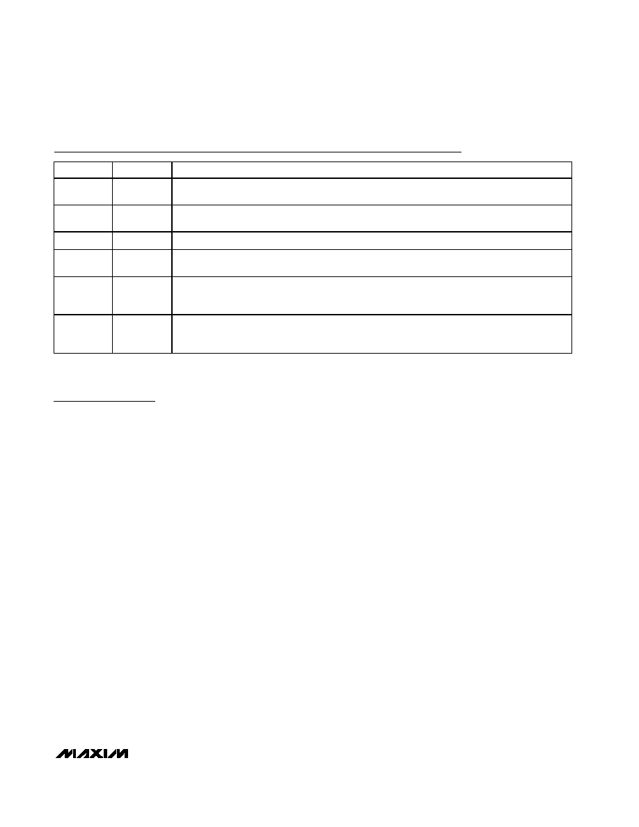
Pin Description
PIN
NAME
DESCRIPTION
1
IN
Input Voltage from Current-Limited Voltage Source (22V max). Bypass to GND with a 0.1
µF
capacitor. The charging current is set by the current limit of the external power supply.
2
GATE
Gate Drive for External PMOS Pass Element. The PMOS device should have a V
GS
threshold
of 2.5V or less (see Selecting External Components).
3
GND
Ground. Connect the battery's negative terminal to GND.
4
EN
Logic-Level Enable Input. Pull low to disable the MAX1736. EN is internally pulled up to V
BATT
+
100mV through 350k
, but draws no current from BATT.
5
CT
Charge Time Control. Sets the minimum on-time, minimum off-time, and the IN detection interval.
Place a 0.33
µF capacitor between CT and GND for most applications (see Selecting External
Components).
6
BATT
Cell Voltage Monitor Input, Precharge Current Output, and MAX1736 Power Source. Connect BATT
to the positive terminal of a single Li+ cell. Bypass BATT with a capacitor to GND (1.5
µF per amp of
charge current).
Detailed Description
The MAX1736 provides a simple, safe, low-cost method
of charging a single-cell Li+ battery with nearly no heat
generation. Combined with a current-limited voltage
source, the MAX1736 provides precharge, fast-charge,
and top-off-charge capabilities. After constant-current
fast charge, top-off safely finishes charging the battery
by pulse-width modulating charge current. The top-off
on-time is kept below the electrochemical time constant
of the cell. The key advantage of this method is that the
charge circuit is small and generates minimal heat
while providing a safe method of charging to ensure
maximum cell life. Figure 1 shows the MAX1736 func-
tional diagram.
Precharge
To protect Li+ cells from damage that may occur if fast
charged from a dead state, the MAX1736 precharges the
Li+ cell with 6mA at the start of a charging cycle when the
cell voltage is below 2.5V. As soon as the cell voltage
reaches 2.5V, the MAX1736 begins fast charging.
Fast Charge
In fast-charge mode, the MAX1736 turns on the exter-
nal P-channel MOSFET. Charging current is set by the
current limit of the external supply; current is not regu-
lated by the MAX1736. The P-channel MOSFET is
used only as a switch, not as a linear regulator.
Therefore, the circuit's power dissipation is minimized,
permitting rapid charge cycles with almost no heat
generation. The external power supply should have a
specified current limit that matches the desired fast-
charge current for the Li+ cell.
With the P-channel MOSFET on, V
IN
will be nearly
equal to V
BATT
. To detect that an input supply is con-
nected, the MAX1736 periodically turns the P-channel
MOSFET off and checks the voltage at IN. During fast
charge, this occurs once every input detection interval
(20s with C
CT
= 0.33µF). During pulsed top-off, input
detection occurs more frequently and is continuous
when the MOSFET is off (see Selecting External
Components).
Pulsed Top-Off
When the battery approaches full charge, its instanta-
neous voltage reaches the BATT regulation voltage and
pulsed top-off begins. The MAX1736 uses a hysteretic
algorithm with a minimum on- and off-time. Cell voltage
is sampled with no charging current to minimize errors
due to battery and cell protection resistance.
If the voltage is below the BATT regulation voltage, the
P-channel MOSFET switches on for a minimum on-time.
If, at the end of the minimum on-time, the cell voltage is
still below the BATT regulation voltage, the switch
remains on until the cell voltage reaches the BATT reg-
ulation voltage. At that point, the P-channel MOSFET
then switches off for at least the minimum off-time. The
minimum on-time is set by CT and should be set below
the electrochemical time constant of the cell. A C
CT
value of 0.33µF sets a minimum on-time of 165ms,
which is adequate for most Li+ batteries.